


To choose an RF Power Amplifier for 50°C sites, you must review rated output, thermal margin, duty cycle, cabinet heat, cooling path, and protection behavior under the highest field temperature, not only a 25°C bench result. A laboratory test is useful because it confirms controlled performance. The risk begins when that result is treated as proof for a sun-exposed cabinet, a compact vehicle bay, or a fixed-site C-UAS enclosure where the module runs longer, hotter, and closer to its protection boundary.
A buyer may compare frequency range, output power, gain, size, voltage, interface, and price before asking the real field question: what temperature will the module actually face around its heatsink and housing? For RF Power Amplifier modules for C-UAS integration, that question should be reviewed together with duty cycle, cooling path, power margin, supply stability, and protection feedback.
In low-altitude security and C-UAS system integration, stable RF output is not proven by one clean bench number. It is proven when the RF chain still behaves predictably under the highest credible field temperature, especially when the same module must work inside outdoor cabinets, vehicle equipment bays, airport perimeter boxes, or critical infrastructure sites.
1. How to Read RF Power Amplifier 25°C Test Data
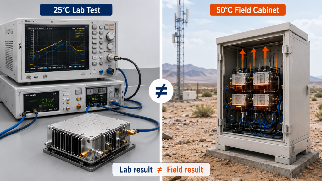
25°C test data is not enough because RF Power Amplifier selection must reflect the final operating environment, not only the controlled bench setup. A laboratory test usually has stable room temperature, clear cable routing, a known load, easier airflow, and shorter observation time. A field cabinet may combine higher ambient temperature, longer operating time, nearby heat sources, and less predictable air movement.
Here’s the engineering point: a 100W result at 25°C is not the same condition as a 100W requirement at 50°C. The first proves controlled performance. The second asks whether the module still has enough thermal and electrical margin after installation.
What Should You Read Behind the Test Number?
You should read the test number together with its operating conditions. Output power without context can mislead procurement teams and delay system debugging.
- Ambient temperature during testing
- Test duration and duty cycle
- Load condition and VSWR
- DC voltage at the module input
- Cooling method and heatsink condition
- Temperature status during the run
Key Takeaway: 25°C data should be treated as a baseline, not as final proof for a high-temperature site.
| Test Detail | Why It Matters | Field Risk If Missing |
|---|---|---|
| Ambient temperature | Defines thermal starting point | Lab result looks too optimistic |
| Duty cycle | Sets average heat load | Output may fall during long runs |
| Cooling method | Controls heat removal | Field cabinet runs hotter |
| Load condition | Affects reflected power | Extra heat and alarms appear |
| Voltage at module | Confirms real supply | Power drops under load |
This table helps you separate a useful test report from an incomplete approval basis.
2. How to Check RF Power Amplifier Thermal Margin
High ambient temperature cuts thermal margin because RF Power Amplifier selection depends on how easily heat can leave the RF power chain. At 25°C, the module has a larger temperature difference between its hot internal parts and the surrounding air. At 50°C, that difference becomes smaller, so the same output level can push the module closer to its protection boundary.
This is where system integrators should pay attention: heat does not disappear at the heatsink. It travels through the RF device, PCB, housing, thermal contact, heatsink, cabinet air, and external environment. For high-power C-UAS modules, thermal strategies for high-power C-UAS modules should be reviewed before the module is approved for hot field operation.

Which Parts of the Heat Path Matter?
The heat path should be reviewed as a chain. One strong part cannot fully compensate for a weak final environment.
- RF device and matching network heat
- PCB and baseplate transfer
- CNC housing contact
- Copper heat spreader or heatsink structure
- Cabinet air movement
- External site temperature
Key Takeaway: High ambient temperature reduces the temperature difference that moves heat away, so the same wattage can become harder to sustain.
| Heat Path Area | Practical Role | High-Temperature Concern |
|---|---|---|
| RF device | Generates heat during output | Junction stress rises faster |
| PCB/baseplate | Moves heat outward | Local hot spots form |
| Housing contact | Transfers heat to structure | Poor contact becomes visible |
| Heatsink | Dissipates heat | Less effective in hot air |
| Cabinet air | Carries heat away | Internal temperature may rise |
This table keeps the discussion focused on heat movement, not only on rated output power.
3. What Makes RF Power Amplifier Output Drop at 50°C
Output power can fall before failure because RF Power Amplifier selection may leave too little room for thermal derating under high ambient temperature. The module does not have to fail completely for the system to lose usable RF performance. It may reduce output, trigger alarm behavior, become unstable after warm-up, or require recovery time between runs.
The practical risk is clear: the user sees “not enough power,” while the root cause may be that the module was selected from a cool bench result and then installed into a hotter, tighter enclosure. This is not always a bad module. It is often a mismatch between the selected module, the cabinet, the duty cycle, and the field temperature.

What Field Symptoms Point to Heat?
Heat-related output loss often appears after time, not at power-on. You should compare cold-start behavior with long-run behavior.
- Output power is normal at first, then falls
- Current changes as temperature rises
- Temperature alarm appears near full load
- Power is stable on dummy load but weak in cabinet
- The issue improves during cooler retesting
- Performance changes with cabinet door open or closed
Key Takeaway: Output drop under high temperature should be investigated as a system condition before it is treated as a simple component defect.
| Symptom | Likely Meaning | First Check |
|---|---|---|
| Output falls after warm-up | Heat accumulation | Case and heatsink temperature |
| Alarm appears during long run | Protection boundary reached | Duty cycle and cabinet heat |
| Stable bench, unstable cabinet | Environment mismatch | Internal cabinet temperature |
| Better at night | Ambient-driven issue | Site temperature trend |
| Power varies by frequency | Weak operating point | Full-band hot-condition data |
This table helps field teams avoid replacing a module before checking the real thermal condition.
4. Why Does Duty Cycle Become Critical at 50°C?
Duty cycle becomes critical at 50°C because RF Power Amplifier selection must account for average heat load, not only peak wattage. A short output burst may pass cleanly, while long-duty operation keeps adding heat until the module, heatsink, and cabinet reach a much harder thermal state. At high ambient temperature, recovery between output periods is also less effective.
Here’s the field reality: a C-UAS platform may not operate like a short factory demonstration. A fixed-site perimeter node, airport equipment box, or vehicle-mounted RF system may need repeated activation or long watch periods.

What Duty Cycle Data Should Be Defined?
Duty cycle should be described in operating language, not vague phrases like “normal use.” The supplier needs enough detail to judge heat accumulation.
- Single activation duration
- Continuous output requirement
- Daily operating time
- Recovery interval between runs
- Number of modules active together
- Signal mode and waveform type
Key Takeaway: Duty cycle tells you whether rated output is a short event or a sustained heat problem.
| Duty Item | What It Controls | Why It Matters at 50°C |
|---|---|---|
| Single run time | Heat buildup per event | Longer runs raise case temperature |
| Daily runtime | Long-term stress | More heat cycles affect reliability |
| Recovery interval | Cooling time | Hot air slows recovery |
| Multi-module operation | Cabinet heat stacking | Local temperature rises faster |
| Signal mode | Average power load | CW and high-duty signals heat more |
This table turns “100W” into a realistic operating requirement.
5. How Can Cabinet Heat Exceed Outdoor Temperature?
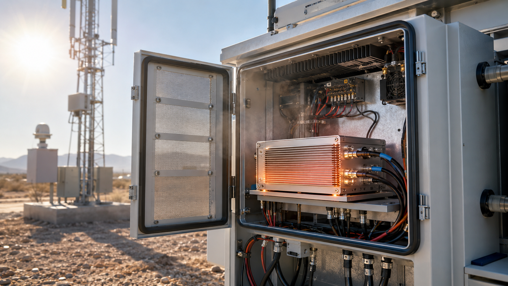
Cabinet heat can exceed outdoor temperature because RF Power Amplifier selection should consider the module’s surrounding air, not only the weather value outside the enclosure. A site may be described as 50°C ambient, but a sealed sun-exposed cabinet can create a hotter local environment around the heatsink. That local temperature is what the module actually feels.
This is where the installation picture matters. Direct sunlight heats the cabinet wall, nearby power supplies add internal heat, cable bundles can block airflow, and multiple RF channels may run at the same time. If the module is installed in an outdoor enclosure, cabinet airflow affects RF Power Amplifier full-load performance because heat must leave the cabinet, not just move inside it.

Where Do Hot Spots Come From?
Hot spots usually come from layout and airflow limits. They are easy to miss when a module is tested outside the final cabinet.
- Sun exposure on metal enclosures
- Power supplies mounted near RF modules
- Long cable bundles across airflow paths
- Narrow gaps around heatsink fins
- Dust filters or blocked vents
- Several modules transmitting together
In an airport counter-UAS RF deployment or critical infrastructure Counter-UAS deployment, this cabinet-level temperature matters because the system may need long-duty stability, not only a clean initial output number.
Key Takeaway: For field approval, the most important temperature is the temperature around the module, not only the outdoor air temperature.
| Heat Source | Cabinet Effect | Selection Risk |
|---|---|---|
| Sun exposure | Raises enclosure temperature | Less thermal margin |
| Power supply heat | Adds local hot air | Faster temperature rise |
| Cable blockage | Reduces airflow | Heatsink works poorly |
| Multi-module operation | Stacks heat sources | Derating risk increases |
| Dust or filter load | Slows exhaust | Long-term heat buildup |
This table explains why cabinet temperature should be part of the RFQ, not an installation afterthought.
6. How to Define RF Power Amplifier Power Margin
Power margin should increase in hot sites because RF Power Amplifier selection must allow for usable output after thermal stress, cable loss, frequency variation, and supply conditions are considered. This does not mean blindly selecting a much larger module. It means the selected module should not be working at the edge of its usable capability under the hottest field condition.
Here’s the engineering point: power margin is not only about compensating feeder loss. In a hot cabinet, margin also protects the system from thermal derating and long-run output drift. Before approving a 50°C site, RF Power Amplifier power margin should be reviewed together with duty cycle, target frequency, antenna path, cabinet temperature, and test evidence.

What Should the Margin Cover?
Power margin should cover the real field chain from module output to required effect. Heat is only one part, but it can tighten every other part.
- Thermal derating risk
- Cable and connector loss
- Antenna distance
- Band-edge weakness
- VSWR stress
- DC voltage drop
Key Takeaway: In high-temperature selection, power margin gives the RF chain room to remain useful after real field losses appear.
| Margin Factor | Field Effect | Selection Response |
|---|---|---|
| High ambient heat | Reduces sustained output | Verify hot-condition operation |
| Cable loss | Reduces antenna-end power | Define output reference point |
| Band variation | Creates weak points | Check full-band evidence |
| VSWR stress | Adds reflected power heat | Review load condition |
| Voltage drop | Limits RF conversion | Check module-side voltage |
This table keeps power margin connected to the whole system, not just a bigger wattage label.
7. Why Do Wideband Points Need High-Temp Evidence?
Wideband points need high-temperature evidence because RF Power Amplifier selection should verify the weakest operating points, not only the easiest center frequency. Different frequency points can have different gain, output power, efficiency, matching behavior, and heat load. A module that looks stable at one frequency may still need closer review near band edges.
The practical risk is clear: high temperature makes weak frequency points more visible. For wideband systems, RF Power Amplifier gain flatness should be reviewed with temperature condition, and verified wideband RF Power Amplifier performance should include more than a single output screenshot.

What Full-Band Data Should You Request?
Full-band data should show how the module behaves across the actual project band. A center-point result is not enough for multi-band C-UAS approval.
- Low, center, and high frequency output
- Gain flatness or gain trend
- Output flatness across the band
- Current draw by frequency
- Temperature during testing
- Load and VSWR condition
Key Takeaway: At high temperature, the weakest frequency point may decide whether the module is suitable for the project.
| Data Item | What It Shows | Why It Matters in Heat |
|---|---|---|
| Output sweep | Power consistency | Finds weak points |
| Gain curve | Amplification trend | Supports calibration |
| Current trend | Electrical load | Indicates thermal stress |
| Edge frequency data | Band limit behavior | Finds worst-case margin |
| Temperature record | Test condition | Connects data to field use |
This table helps you judge wideband capability as tested evidence, not only as a frequency label.
8. What RF Power Amplifier Protection Cannot Solve
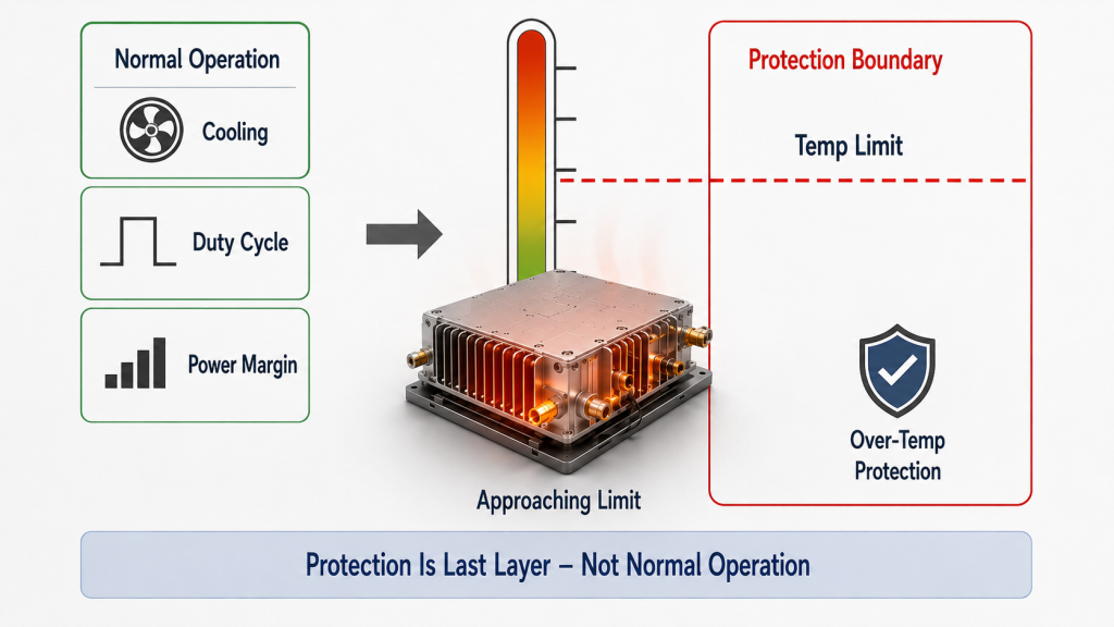
Temperature protection is not enough because RF Power Amplifier selection should prevent routine operation at the thermal limit. Protection is necessary, but it is the last safety layer, not the normal operating plan. If a module frequently enters thermal alarm, derating, shutdown, or restart, the system may be safe from damage but still unstable for the mission.
This is where protection feedback becomes useful. VSWR, temperature, and voltage protection help the system identify abnormal stress and protect the module. They do not replace correct high-temperature selection, cabinet design, duty-cycle review, and test-condition confirmation.
What Protection Feedback Should Be Checked?
Protection feedback should be readable by the system controller or maintenance team. Otherwise, field teams may only see unstable output without knowing why it happened.
- Temperature alarm or derating status
- Forward power feedback
- Reflected power or VSWR alarm
- Voltage alarm
- Current status
- Enable, fault, and reset state
Key Takeaway: Temperature protection should protect the module from abnormal heat, not compensate for a selection that ignored the highest ambient temperature.
| Protection Signal | What It Helps Identify | First Engineering Check |
|---|---|---|
| Temperature alarm | Heat stress | Cabinet heat and duty cycle |
| VSWR alarm | Load mismatch | Antenna and cable path |
| Voltage alarm | Supply instability | DC wiring and power supply |
| Current status | Electrical stress | Load and waveform condition |
| Reset behavior | Recovery logic | Control interface design |
This table shows why protection data should be included in field validation, not checked only after failure.
9. What RF Power Amplifier Data Should You Share?
You should share temperature data before RFQ because RF Power Amplifier selection becomes more accurate when the supplier knows the real site temperature, cabinet condition, duty cycle, cooling path, and target output point. A request that only says “100W, 28V, this frequency band” leaves too much thermal risk hidden.
This does not require perfect simulation at the first message. A practical range such as 40°C, 45°C, 50°C, or 55°C is already useful. If the module will be installed in a sealed outdoor cabinet, vehicle equipment bay, airport perimeter box, or critical infrastructure enclosure, say that early.

What Should Your RFQ Include?
A useful RFQ should describe how the module will be used and where heat will go. This helps the factory judge whether standard selection is enough.
- Maximum outdoor ambient temperature
- Expected cabinet internal temperature
- Module location inside the enclosure
- Outdoor, vehicle, or fixed-site use
- Direct sunlight exposure
- Duty cycle and run duration
- Cooling method and mounting direction
- Target output at module port or antenna end
Key Takeaway: A clear RFQ reduces the chance of approving a module that passes the lab but struggles in the field.
| RFQ Item | Why It Matters | Example |
|---|---|---|
| Outdoor ambient | Defines site heat | 50°C maximum |
| Cabinet temperature | Defines module environment | May exceed outdoor air |
| Duty cycle | Defines heat accumulation | Long-duty or short burst |
| Output reference | Defines power target | Module port or antenna end |
| Cooling path | Defines heat removal | Heatsink, airflow, enclosure |
This table can be used as a simple pre-quotation checklist for RF engineers and procurement teams.
10. How Should You Approve RF Amplifiers for Hot Sites?
You should approve RF amplifiers for hot sites by confirming maximum ambient temperature, cabinet heat, target output, frequency band, duty cycle, cooling path, supply margin, protection behavior, and repeatable test evidence. RF Power Amplifier selection should start from the hottest credible operating condition, not from the most comfortable test bench.
This is where early engineering communication saves time. High-temperature sites should confirm 28V RF Power Amplifier supply margin because power supplies, DC cables, and module input voltage can face additional stress during long-duty operation. As a source factory for RF Power Amplifier modules and C-UAS core components, RF SKYPOWER can review frequency band, target power, duty cycle, cabinet heat, thermal path, protection logic, and report conditions before final approval.

What Approval Steps Should Come First?
Approval should connect RF, thermal, DC, and mechanical conditions before procurement is locked. Do not approve wattage first and discover the thermal environment later.
- Confirm maximum outdoor and cabinet temperature
- Define module-side and antenna-side power targets
- Check low, center, and high frequency points
- Define duty cycle and operation time
- Review heatsink, housing, and cabinet airflow
- Confirm DC voltage at the module under load
- Check VSWR, temperature, and voltage feedback
- Request test data with stated conditions
Key Takeaway: Hot-site approval should prove that the RF module can sustain usable output under the same stress the field system will create.
| Approval Step | Main Question | Evidence Needed |
|---|---|---|
| Temperature | How hot is the module area? | Ambient and cabinet data |
| Power target | Where is output required? | Module or antenna reference |
| Frequency | Which points must work? | Full-band or multi-point data |
| Duty cycle | How long will it run? | Operating profile |
| Cooling | How does heat leave? | Mechanical and cabinet review |
| Supply | Can DC support full load? | Voltage and current data |
| Protection | Can stress be monitored? | Alarm and feedback logic |
This table gives engineering, purchasing, and supplier teams a shared approval framework.
FAQ
Can I use 25°C test data for RF Power Amplifier approval?
Yes, but only as baseline evidence. You still need to compare it with the highest field temperature, duty cycle, cabinet condition, cooling method, and target output point.
What’s the best temperature to share before quotation?
Share the highest credible temperature around the module. If you only know outdoor temperature, explain whether the module will be inside a sealed cabinet, vehicle bay, or sun-exposed enclosure.
How do I know if high temperature is causing output loss?
Check whether output drops after warm-up, temperature alarms appear, current changes, or performance improves during cooler retesting. These signs point to limited thermal margin.
Can a larger RF Power Amplifier solve high-temperature risk?
Not by itself. A larger module may provide more power margin, but it can also create more heat, so cooling, duty cycle, supply stability, and cabinet design still matter.
What’s the best evidence for hot-site selection?
The best evidence states frequency point, output power, input drive, DC voltage, current, load condition, ambient temperature, duty cycle, test duration, and temperature status.
Conclusion
Ambient temperature changes RF Power Amplifier selection because it affects thermal margin, sustained output, power margin, duty cycle limits, cabinet heat, wideband evidence, protection behavior, RFQ quality, and final approval. A 25°C bench result can confirm controlled performance, but it cannot automatically prove that the same module will stay stable inside a 50°C field cabinet, vehicle enclosure, airport equipment box, or critical infrastructure site.
For system integrators, RF engineers, and procurement reviewers, the practical decision is clear: define the highest ambient temperature before final module approval. Then review cabinet temperature, target output, frequency band, duty cycle, thermal path, power margin, supply margin, protection feedback, and repeatable test evidence.
RF SKYPOWER can help review maximum field temperature, module operating conditions, cooling path, power requirements, protection logic, and report conditions before your final project decision. If your project has not confirmed ambient temperature, cabinet heat, duty cycle, target output, and cooling path, contact us today before locking the final RF module choice.
Reliable C-UAS RF performance is built where field temperature, controlled RF output, thermal design, and source-factory verification meet the same engineering standard.