


Duty cycle affects RF power amplifier performance and reliability by changing how long the amplifier must sustain output power, heat, current demand, load stress, and protection behavior under real operating conditions. A module that reaches 100W during a short bench test may not hold the same output after 30 minutes, two hours, or a full duty cycle requirement inside a multi-module system. That difference matters for system integrators, RF engineers, and procurement reviewers because peak power, intermittent output, and True CW output are not the same capability.
For a C-UAS cabinet, fixed-site RF platform, or industrial RF system, the question is not only whether an amplifier can reach a target wattage. You also need to know whether the RF Power Amplifier modules can hold that power at the required frequency, thermal condition, DC input level, antenna load, and operating time. RF Power Amplifier duty cycle should therefore be defined before finalizing wattage, frequency range, cooling, power supply, and acceptance testing.
1. What Does RF Power Amplifier Duty Cycle Mean?
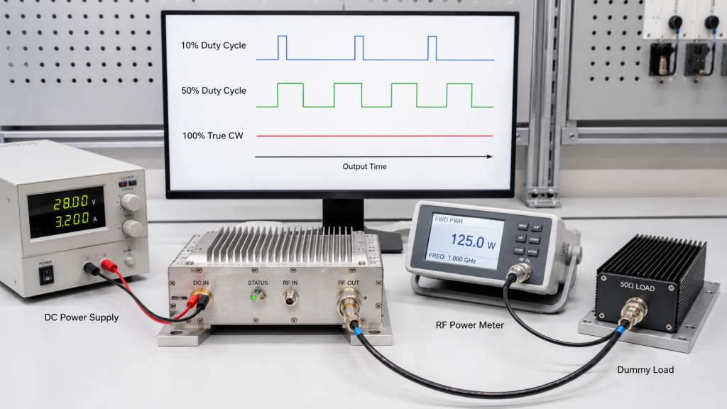
RF Power Amplifier duty cycle means the percentage of time the amplifier must transmit during a defined operating period. In selection work, it is not just a waveform term. It tells you how long the module must survive its output power without drifting, overheating, triggering protection, or losing field reliability.
Here’s the engineering point: a 10% duty cycle gives the module recovery time, while 100% duty cycle turns the same wattage into a continuous thermal and electrical load. The amplifier, heatsink, cabinet airflow, DC cable, RF connector, antenna path, and protection logic all experience different stress when the output is held instead of pulsed.
Why does duty cycle change the selection question?
Duty cycle changes the selection question because wattage alone does not describe operating severity. You should define:
- Peak output power
- Average output power
- Single run time
- Daily accumulated run time
- Ambient temperature
- Cooling method
- Load condition
- Acceptance test duration
Key Takeaway: Duty cycle turns a simple wattage request into a real operating requirement. If you do not define it early, the supplier cannot judge whether the amplifier is suitable for the field condition.
| Duty Cycle Condition | What It Means | Selection Risk |
|---|---|---|
| Low duty cycle | Short transmit time with cooling gaps | Peak data may be enough for screening |
| High duty cycle | Long transmit time with limited recovery | Heat and current stress rise |
| True CW | Continuous output without planned off-time | Full thermal stability must be proven |
This table shows why the same rated power can mean different engineering risk.
2. How to Compare Peak Power and True CW RF Power Amplifier Output
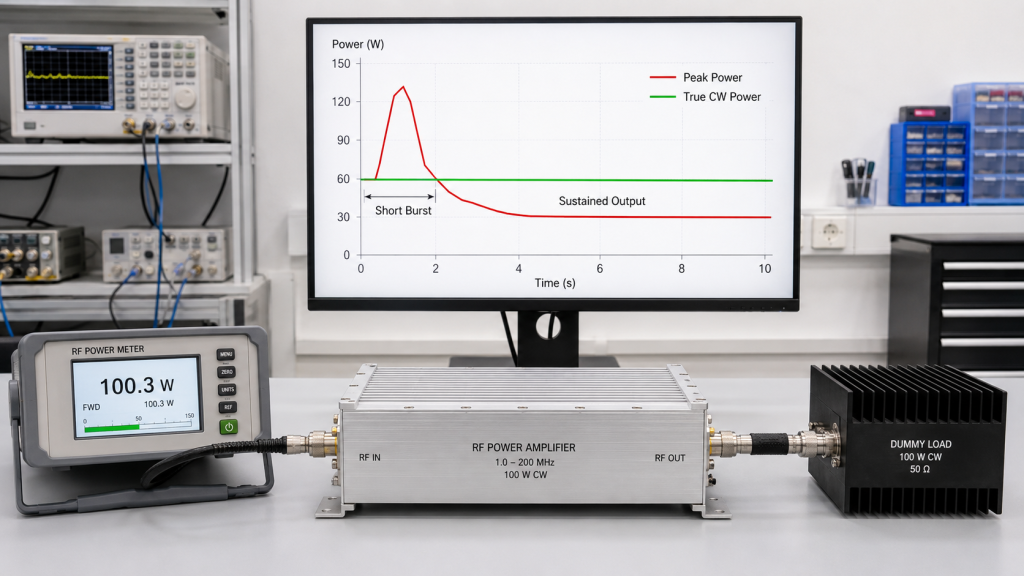
Peak power and True CW power are different because peak power shows what an amplifier can reach briefly, while True CW shows what it can hold continuously. RF Power Amplifier duty cycle is the condition that separates these two numbers in real selection work.
A supplier may say a module can reach 100W, 200W, or 500W, but you still need to ask how that number was measured. Was it measured cold or hot? Was it held for seconds, minutes, or hours? Was the load a clean 50-ohm dummy load or a realistic antenna path?
What should you ask before accepting a power rating?
Before accepting a rating, ask for the conditions behind the number:
- Frequency point or full-band sweep
- Input drive level
- DC voltage at module terminals
- Current under load
- Ambient temperature
- Test duration
- Load VSWR
- Protection status
- Serial-number test report
Key Takeaway: Peak power is useful, but it cannot replace continuous power evidence. True CW capability must be tied to test duration, heat balance, and repeatable data.
| Power Term | What It Proves | What It Does Not Prove |
|---|---|---|
| Peak power | Short-time output ceiling | Long-term stability |
| Psat | Saturated output condition | Safe continuous operation |
| True CW power | Sustained output capability | Performance under every antenna condition |
The practical risk is clear: using peak data as CW data can create sample approval followed by field failure.
3. How to Manage RF Power Amplifier Thermal Stress from Duty Cycle
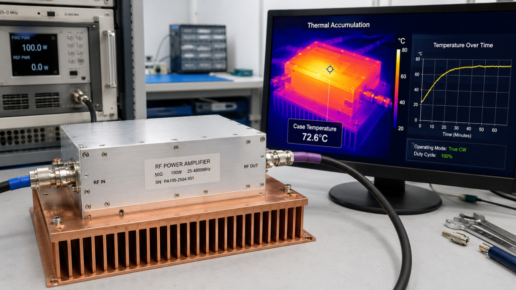
Duty cycle changes thermal stress by reducing the time available for the amplifier to cool between transmit periods. RF Power Amplifier duty cycle directly affects junction temperature, heatsink temperature, enclosure temperature, cabinet airflow demand, and long-term output stability.
RF amplifiers convert DC energy into RF output, but the unused energy becomes heat. At low duty cycle, that heat may dissipate during off-time. At high duty cycle or True CW, heat keeps accumulating until the system reaches thermal balance or enters power reduction, alarm, or shutdown.
What thermal signs should you watch?
Long-duty thermal stress may appear gradually rather than as an instant failure. Watch for:
- Slow output power drop
- Gain drift after warm-up
- Rising case temperature
- Hot connector zones
- Fan speed increase
- Temperature alarm events
- Automatic derating
- Sudden shutdown after stable startup
Key Takeaway: Long-duty operation makes thermal design more important than cold-start output. A cold peak screenshot is less useful than a hot-state stability curve.
| Thermal Factor | Why It Matters | What To Request |
|---|---|---|
| Heat spreader | Moves heat away from devices | Material and mounting details |
| Thermal interface | Controls contact resistance | Assembly process data |
| Airflow | Removes cabinet heat | Installed airflow condition |
| Ambient temperature | Changes thermal margin | Test temperature record |
This is where duty cycle turns RF selection into a thermal stability review.
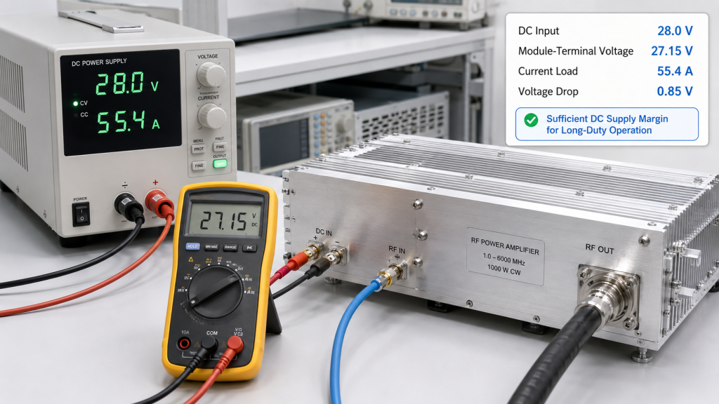
4. What DC Power Margin Does RF Power Amplifier Duty Cycle Require?
Duty cycle affects DC power supply margin because continuous RF output requires continuous DC support. RF Power Amplifier duty cycle therefore changes how you size current capacity, cable gauge, voltage drop allowance, ripple control, grounding, and multi-module power budget.
At low duty cycle, average current may look moderate even if peak current is high. At high duty cycle or True CW, average current moves closer to sustained full-load demand. If the supply rail sags, the RF output may drop even though the amplifier itself is not defective.
What DC data should be reviewed?
For high-duty projects, review the DC chain under real RF load, not only idle conditions. Ask for:
- Maximum current
- Average current at duty cycle
- Startup current
- Module-terminal voltage
- Voltage drop through cables
- Ripple and noise level
- Shared rail behavior
- Simultaneous multi-module loading
Key Takeaway: A duty-cycle requirement is also a power-supply requirement. Stable RF output starts with stable DC input, especially in long-duty and multi-module systems.
| DC Condition | Possible RF Symptom | Practical Check |
|---|---|---|
| Voltage sag | Output power drops | Measure at module terminals |
| Current limit | Gain compression | Test full-load current |
| Ripple | Output instability | Check DC rail quality |
| Shared rail overload | Module interaction | Test simultaneous operation |
For deeper power-chain review, use stable DC input under real RF load as part of the system acceptance plan.
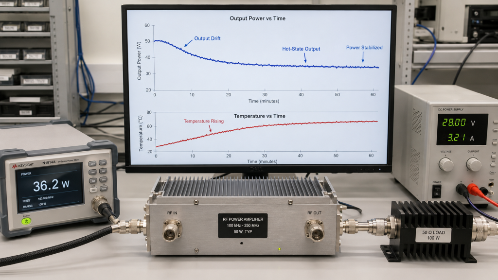
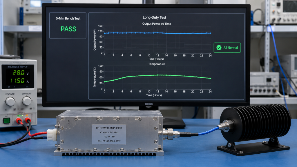
5. Why Can Output Power Drift During Long-Duty Operation?
Output power can drift during long-duty operation because temperature, DC voltage, device bias, matching networks, and protection logic all change as the amplifier warms up. RF Power Amplifier duty cycle decides whether these effects remain minor or become visible in acceptance testing.
A module may start at 100W and slowly move downward after warm-up. That does not always mean poor design; it may show that the system has reached a thermal, power, or load limit. What matters is whether the final stable output still meets the project requirement.
How should output stability be judged?
Output stability should be judged over time, not by the highest number at startup. Useful records include:
- Output power versus time
- Temperature versus time
- DC current versus time
- Module-terminal voltage
- Alarm log
- Test frequency points
- Load condition
- Warm-up and hot-state data
Key Takeaway: For long-duty projects, a power curve is more useful than a single peak reading. You need to know what the amplifier holds after the system is hot.
| Test Method | What It Shows | Weakness |
|---|---|---|
| Startup reading | Initial output | Hides thermal drift |
| Short bench test | Basic function | Cannot prove CW stability |
| Long-duty curve | Stability over time | Requires proper setup |
| Hot-state retest | Realistic performance | Needs controlled conditions |
The highest wattage number is not always the most useful number.
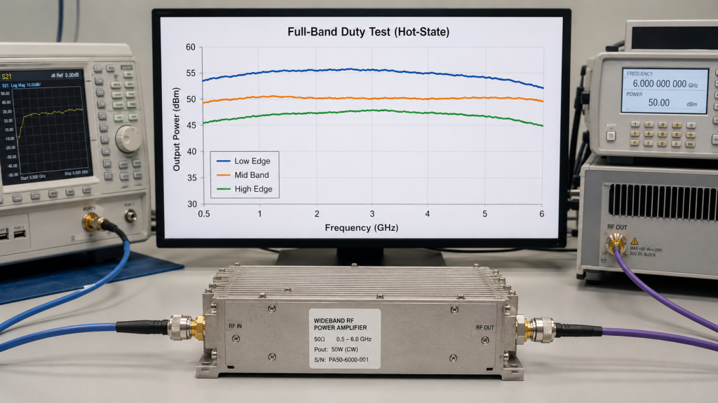
6. How Do Frequency Range and Duty Cycle Work Together?
Frequency range and duty cycle work together because some frequency points create more heat, lower gain, higher drive demand, or weaker output stability. RF Power Amplifier duty cycle can make band-edge weakness more obvious during long operation.
A module that performs well at a center frequency during a short test may behave differently at the low or high edge of its rated band. Wideband modules should be checked at low, middle, and high points under the required duty cycle, especially when the system depends on stable coverage across multiple bands.
What should full-band duty-cycle testing include?
Full-band duty-cycle testing should connect frequency behavior with sustained output. Check:
- Low, mid, and high frequency power
- Gain flatness after warm-up
- Efficiency changes by frequency
- Current draw at each point
- Temperature trend at each point
- Protection status
- Repeatability by serial number
Key Takeaway: Frequency range tells where the amplifier must work; duty cycle tells how long it must stay stable there. You need both conditions in the same test plan.
| Frequency Point | Short Test Risk | Long-Duty Risk |
|---|---|---|
| Low edge | Matching may look acceptable | Heat may rise faster |
| Center point | Often strongest result | May not represent full band |
| High edge | Gain may drop | More drive may be needed |
| Wideband sweep | Shows spread | Must be repeated hot |
For C-UAS projects, full-band performance verification is a stronger basis than one convenient center-frequency reading.
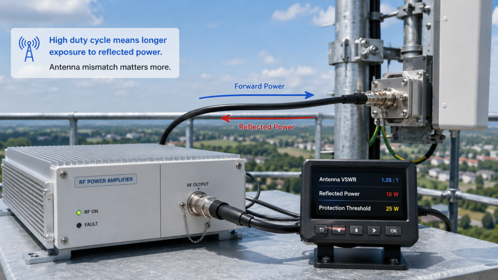
7. What VSWR Risks Increase with High RF Power Amplifier Duty Cycle?
Antenna VSWR matters more at high duty cycle because reflected power becomes a continuous stress instead of a short event. RF Power Amplifier duty cycle makes load mismatch more dangerous for the output stage, matching network, connectors, and protection system.
A laboratory dummy load is usually close to 50 ohms, but field antennas are affected by cable length, adapters, installation height, nearby metal, weatherproofing, and vibration. Low duty cycle may allow recovery time. High duty cycle keeps pushing RF power into a less ideal load.
What load conditions should be checked?
Do not judge the amplifier only by dummy-load performance. Review:
- Antenna VSWR across working band
- Cable and connector loss
- Adapter count
- Waterproof connector quality
- Installed antenna position
- Reflected power alarm threshold
- Protection recovery behavior
- Output stability under real load
Key Takeaway: A load mismatch is more severe when the amplifier must push power into it continuously. VSWR protection reduces damage risk, but it does not remove the need for system-level testing.
| Load Condition | Short Test Result | High-Duty Risk |
|---|---|---|
| Clean dummy load | Stable output | May not represent field antenna |
| Mild mismatch | Small reflected power | Heat accumulates |
| Poor connector | Intermittent reading | Alarm or shutdown |
| Detuned antenna | Coverage loss | Output stage stress |
If your installation shows alarms or unstable output, check for field failure from antenna mismatch before blaming the module alone.
8. Why Should Integrators Avoid Short Bench Tests Alone?
Integrators should avoid short bench tests alone because short tests can approve a sample for the next step but cannot prove long-duty reliability. RF Power Amplifier duty cycle must be reflected in the test duration, thermal condition, load condition, and acceptance criteria.
A five-minute test may confirm basic output, control response, and connection correctness. It cannot prove that the module will hold stable output after heat soak, shared DC loading, fan speed changes, cabinet temperature rise, or antenna mismatch in the final system.
What should a stronger test report include?
A stronger test report should make the operating condition repeatable. Include:
- Serial number
- Frequency points
- Output power
- Input drive
- DC voltage and current
- Ambient temperature
- Load type and VSWR
- Cooling method
- Run time
- Temperature curve
- Alarm status
Key Takeaway: Test duration should match project risk. The closer the project is to True CW or high-duty operation, the less acceptable a short bench screenshot becomes.
| Test Evidence | Useful For | Not Enough For |
|---|---|---|
| Peak screenshot | Initial screening | CW reliability |
| Short dummy-load test | Basic function | Field load behavior |
| Hot-state curve | Stability review | Every installation variable |
| Serial-number report | Traceability | Poor test design |
This is where system integrators should pay attention: the test must answer the same question the field will ask.
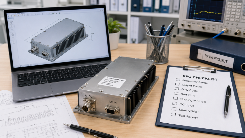
9. How to Write RF Power Amplifier Duty Cycle Details in an RFQ
Duty-cycle clues should be shared before quotation because many buyers do not know the exact duty cycle percentage at the first RFQ stage. For RF Power Amplifier selection, the supplier does not only need a frequency band and target wattage; it also needs to understand how the module will actually be used in the system.
Instead of forcing the buyer to calculate every parameter, a practical RFQ should describe the operating rhythm. If you know the duty cycle, write it clearly. If you do not, describe the transmit time, off-time, single run duration, daily operating pattern, cooling method, and installation environment so the source factory can help translate the application into a suitable test condition.
What should the buyer describe if duty cycle is unclear?
If the exact duty cycle is unclear, describe the working scenario in engineering language:
- How long the amplifier transmits each time
- How long it rests between transmit periods
- Whether operation is pulsed, intermittent, or continuous
- Whether multiple modules work at the same time
- Expected ambient temperature
- Cabinet airflow or cooling method
- Power supply voltage and available current
- Antenna or load condition
- Whether hot-state output must be verified
Key Takeaway: The RFQ does not need to be a perfect test specification at the first step. It must give enough real operating clues for the supplier to judge whether the amplifier needs peak-output, long-duty, or True CW capability.
| RFQ Information | If Known | If Not Known |
|---|---|---|
| Duty cycle | State the percentage | Describe transmit and rest rhythm |
| Run duration | State continuous run time | Describe expected use cycle |
| Cooling method | State fan, heatsink, or cabinet airflow | Share installation space and airflow limits |
| Load condition | State dummy load, antenna, or VSWR target | Describe antenna path and connector setup |
| Multi-module use | State simultaneous operation | Share system architecture |
This makes the quotation more accurate because the supplier can match the module, thermal margin, protection design, and test report to the real application instead of guessing from wattage alone.
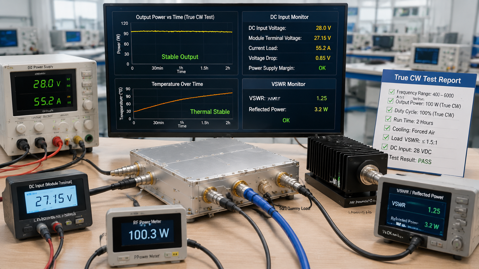
10. How Does Source-Factory Testing Confirm True CW Reliability?
Source-factory testing confirms True CW reliability by testing the amplifier under repeatable conditions that match the project duty cycle. RF Power Amplifier duty cycle should be verified with controlled frequency, power, DC input, cooling, load, temperature, and serial-number records.
RF SKYPOWER’s role as a source factory is most relevant here: the useful value is not a loud claim about wattage, but the ability to connect RF design, CNC housing, copper heat spreading, protection logic, production consistency, and test reporting under one engineering workflow. For integrators, that makes the discussion more specific and more testable.

What factory capability matters most?
For True CW or high-duty projects, factory capability should support repeatable verification. Look for:
- Wideband RF module design support
- CNC enclosure control
- Copper heat spreader options
- VSWR protection
- Temperature protection
- Voltage protection
- Burn-in or long-run test process
- Serial-number test records
- Engineering communication during RFQ review
Key Takeaway: True CW reliability is not a slogan. It is a repeatable test result under the same duty cycle the project will actually use.
| Factory Capability | Why It Helps | Buyer Value |
|---|---|---|
| In-house RF engineering | Faster requirement review | Fewer mismatched samples |
| Thermal structure control | Better heat path consistency | More stable output |
| Protection testing | Safer abnormal-load behavior | Lower damage risk |
| Traceable reports | Repeatable evidence | Easier acceptance review |
You can also review source-factory capabilities when judging whether a supplier can support long-duty projects beyond catalog data.
FAQ
Can I use peak power as my CW power rating?
No. Peak power only shows short-time output capability. CW power must be proven under continuous operation, stable temperature, correct DC input, and realistic load conditions.
What’s the best duty cycle for RF power amplifier testing?
The best duty cycle is the one that matches your real operating condition. If the system will run continuously, the test should verify True CW behavior rather than short intermittent output.
How do I know if my amplifier needs True CW testing?
You need True CW testing if the amplifier must hold output for long periods without planned cooling intervals. This is common in fixed sites, high-duty RF systems, and multi-module C-UAS platforms.
Can better cooling compensate for high duty cycle?
Sometimes. Better cooling can improve thermal margin, but it cannot fix weak DC supply, poor load match, insufficient device margin, or unverified full-band behavior.
What should I ask the supplier before sample approval?
Ask for frequency, power, duty cycle, test duration, temperature curve, DC voltage and current, load condition, protection status, and serial-number test data. Those details make the result easier to repeat.
Conclusion
RF Power Amplifier duty cycle affects power selection, thermal stress, DC supply margin, output drift, frequency performance, VSWR risk, bench testing, RFQ quality, and True CW reliability. The main lesson is simple: do not separate wattage from operating time. A module that reaches target power briefly is not automatically suitable for long-duty or continuous operation.
RF SKYPOWER can help integrators review frequency range, output power, duty cycle, cooling method, DC input, load condition, protection requirements, and repeatable factory testing before sample approval or batch procurement. For duty-cycle-based RF module selection, contact us today with your operating condition and acceptance method.
Reliable RF integration starts when peak wattage stops being the only question and real duty-cycle performance becomes the engineering standard.