


Life Science & Medical
RF Energy Core
Customizable 30MHz-20GHz / 10W-1000W platform explicitly engineered for global OEMs. Supporting Continuous Wave (CW) and Precision Pulse Width Modulation (PWM) for electrosurgery, RF diathermy, microwave ablation, and lab plasma systems.

Solid-State High-Linearity Amplifiers (PA)
Leveraging 3rd-generation GaN (Gallium Nitride) semiconductor technology, this core delivers high-density RF output. It enables flexible customization from 10W to 1000W, allowing integration into diverse therapeutic and ablation applications with scalable energy footprints.
Agile Digital Control Signal Board
Built on an agile RF architecture with native standard serial buses. This grants systems the ability to lock onto single frequencies with absolute stability while executing nanosecond-level pulse modulation for extremely precise energy dosing.
Direct access to our engineering team to start your custom RF solution
Evaluate Our PA ModulesThree Core Engineering Constraints for Medical Energy System Integration
RF energy acts directly on target tissues. Navigating medical safety reviews requires overcoming three critical engineering variables in your core components.
01 Bias Transient Surges
Ablation and intermittent cutting rely on heavy pulse modulation. This continuous switching demands robust resilience against repetitive enable/disable shocks, ensuring hardware does not physically break down over prolonged operations.
02 Energy Field Distortion
Harmonic suppression and distortion control across the RF chain directly dictate whether energy dispersion matches pre-surgical planning. This metric determines pass or fail in medical EMC compliance reviews.
03 Enclosure Thermal Loss
Medical and lab hardware aims for quiet, desktop form factors. Low DC conversion efficiency traps waste heat inside sealed chassis, leading to severe thermal drift and a stark decline in system reliability.
Identify integration risks before hardware selection.
Check RF RisksComponent Vulnerability Under High-Density Pulsing and Internal Routing
Clinical environments demand precision pulsing, exposing base hardware to intense physical and electrical stress.
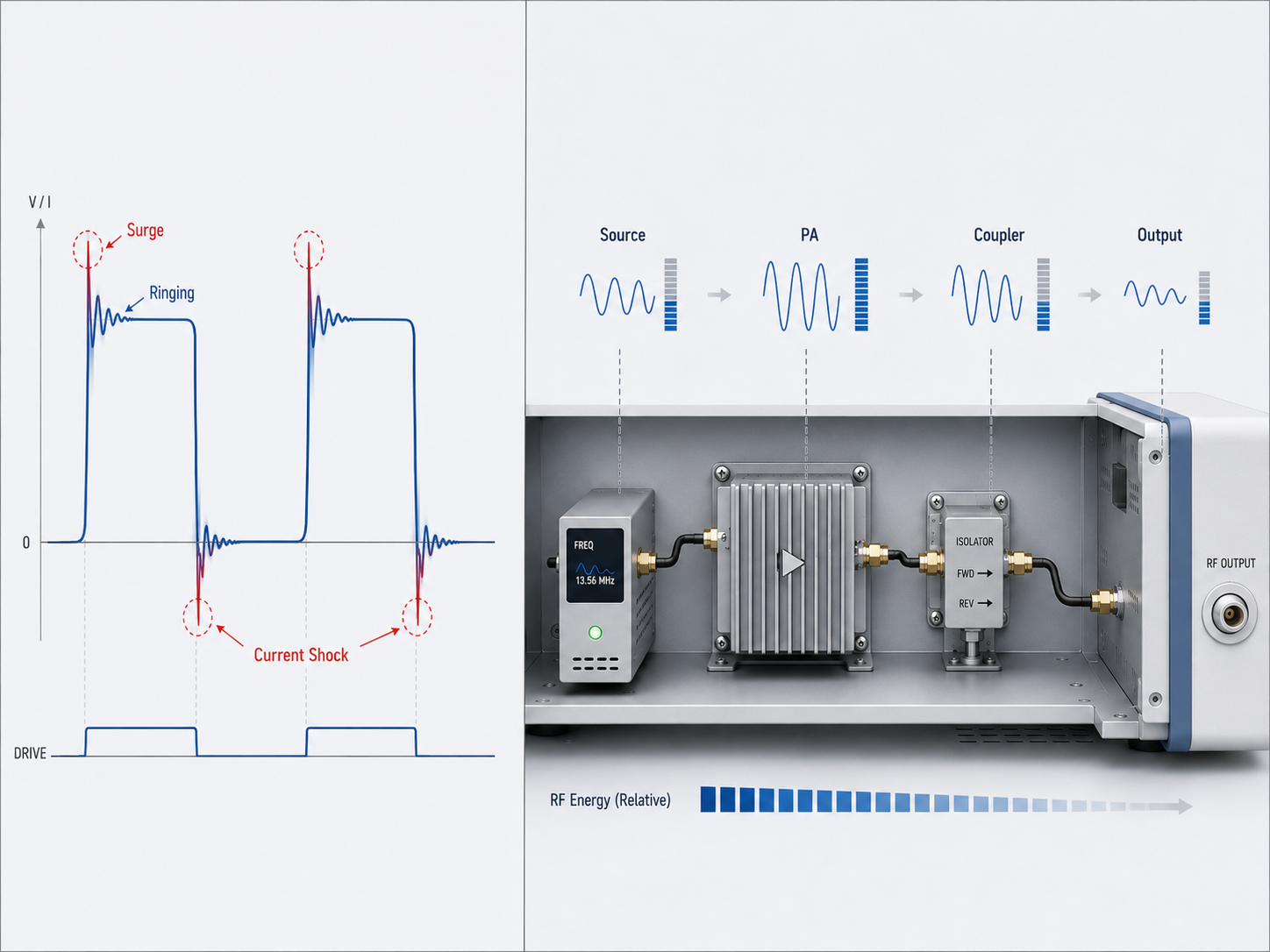
Severe di/dt Shocks
To achieve precise energy delivery, medical systems heavily rely on pulse-width modulation. This subjects the amplifier's bias circuitry to severe instantaneous current variations during toggling.
Bias Circuit Fatigue
Standard components lack the electrical elasticity required for dense on/off cycles. The constant bombardment on the rising and falling edges accelerates component fatigue at the semiconductor junction level.
Internal Chassis Loss
RF signals incur unavoidable transmission attenuation as they travel from the source to the PA, and through internal isolators and coaxial cables before finally reaching the equipment's front panel.
Need cleaner RF output for medical or life-science equipment?
View Clean Spectrum ModulesUncontrolled Transients
→ Amplifier Breakdown & Power Loss
Unmanaged transient surges and internal signal degradation directly compromise the surgical operation envelope.
Irreversible Bias Breakdown
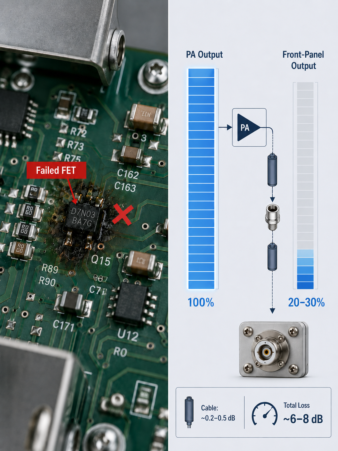
Amplifiers lacking dedicated surge suppression suffer breakdown in biasing FETs or RF switches. Accumulated voltage spikes will physically puncture the circuit, rendering the module dead.
Mid-Operation Freeze
A bias breakdown triggers an immediate short circuit within the energy generation chain. This causes the entire medical device to freeze suddenly during critical treatment phases, endangering procedural flow.
Front-Panel Power Deficit
Uncompensated internal interface and cabling loss drains active power. The actual output measured at the front-panel connector drops significantly below the core module's native capability.
Uncontrolled harmonics can turn RF energy into a compliance and performance risk.
See Solid-State SolutionsMicrosecond Control and Loss Compensation Architecture
We secure your RF energy delivery through rapid solid-state switching and precision signal calibration.
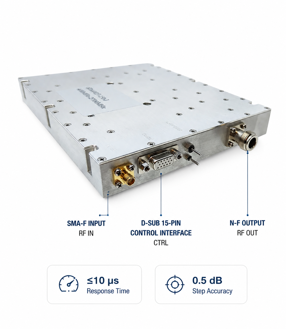
≤ 10 μs Solid-State Switching
Designed with fully solid-state bias networks supporting standard D-Sub 15-Pin interfaces, this architecture eliminates mechanical fatigue points. It achieves a rapid PA Enable/Disable time of ≤ 10 μs, safely withstanding hundreds of thousands of switching cycles without voltage-surge breakdown.
0.5 dB Precision Gain Compensation
Addressing physical signal drop across internal chassis components, the hardware features a gain adjustment step size of 0.5 dB. Medical OEMs can utilize standard serial commands to meticulously fine-tune output gain, exactly offsetting internal attenuation to match front-panel requirements.
Low Return Loss Interface Optimization
Engineered with a standard Input SMA-F and Output N-F connector architecture. We enforce strict internal port impedance matching to drive internal reflection loss down to absolute minimums, aggressively shielding the amplification core from damaging reflected energy feedback.
Eliminate sudden freezes and power deficits directly at the hardware layer.
Configure Your RF ModuleHarmonic Distortions
& Spurious Emissions
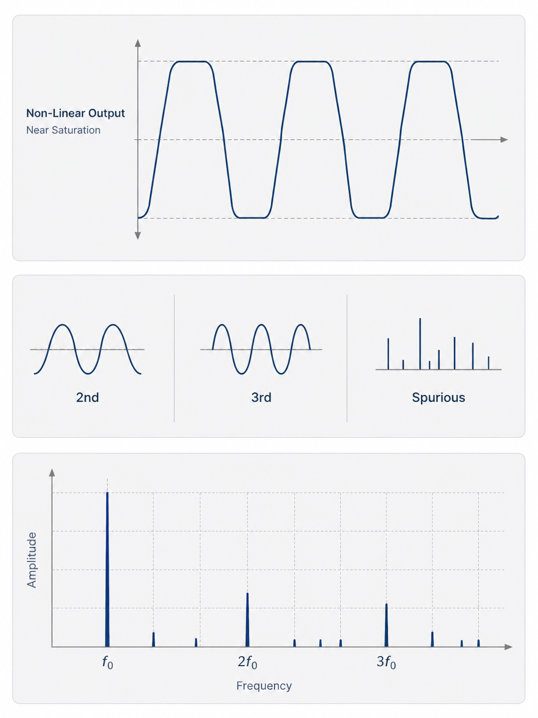
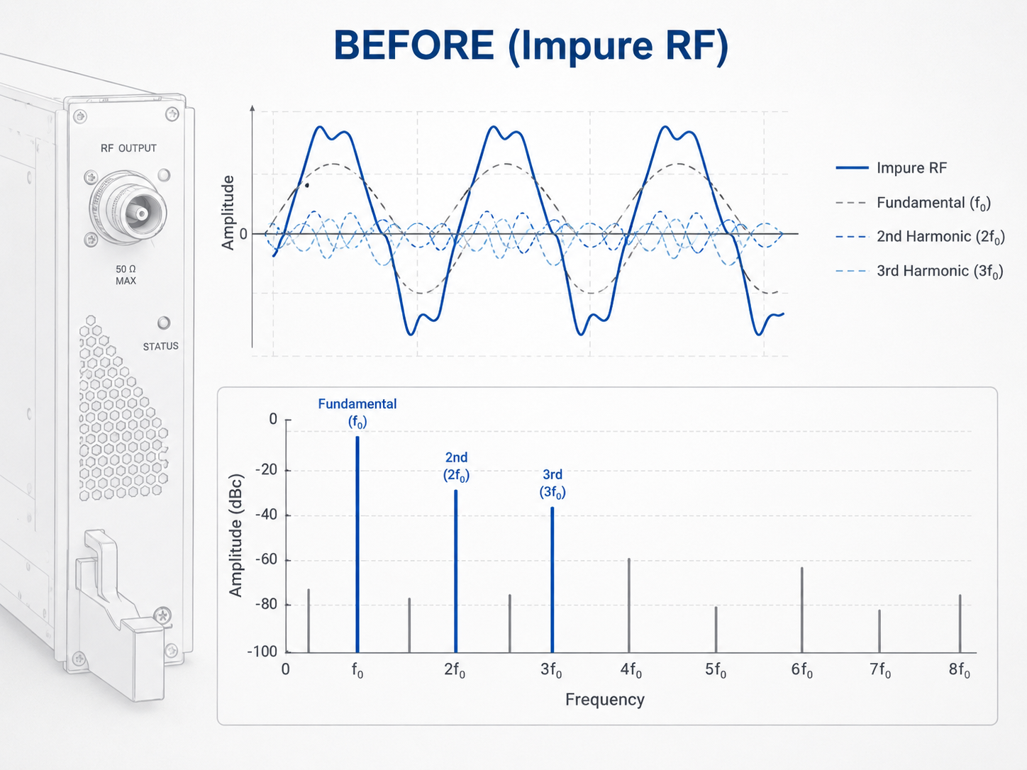
When driving high-power RF energy near saturation, core amplifier stages experience gain compression. This introduces severe non-linear fundamental waveform distortion, elevating 2nd and 3rd harmonics and producing out-of-band spurious emissions.
High-Power Gain Compression
Driving RF energy near saturation heavily compresses the amplifier's gain stages. This introduces severe fundamental waveform distortion, compromising the predictability of clinical energy delivery.
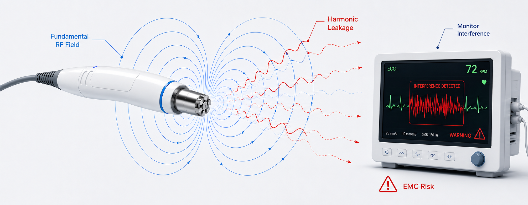
Native Harmonic Leakage
Inherent wideband profiles naturally generate 2nd and 3rd harmonics. Left uncontrolled, up to 10% of generated RF power bleeds into unintended frequency bands, wasting critical system energy.
Out-of-Band Spurious Emissions
Uncontrolled amplification breeds spurious emissions around the primary carrier frequency. These rogue signals pollute the operating spectrum and threaten adjacent equipment stability.
Harmonics and spurious emissions can turn RF output into compliance risk.
View EMC Compliance RisksUneven Energy Fields and EMC Audit Failures
Warped Energy Field Geometry
Biological tissues exhibit varying dielectric properties across different frequencies. Leaked harmonic power forcibly alters the localized energy field, destroying the intended ablation geometry and boundary.
Operating Room Interference
Excessive spurious emissions broadcast raw electromagnetic noise into the surgical suite. This bleeds into highly sensitive monitors and disrupts critical patient telemetry and other precision instruments.
Medical EMC Audit Failure
High harmonic and spurious levels directly violate strict medical electrical safety limits. This immediately triggers failure in mandatory EMC compliance audits, stalling your entire system's market entry.
Protect nearby electronics before EMC issues delay certification.
Discuss EMC RequirementsUltra-Linear Cascading & CNC Filter Integration
Precision bias alignment and CNC cavity filtering suppress harmonic and spurious output before it reaches the applicator. Built for OEM systems that require clean RF energy, repeatable output, and EMC-ready architecture.
Dynamic Non-Linear Alignment
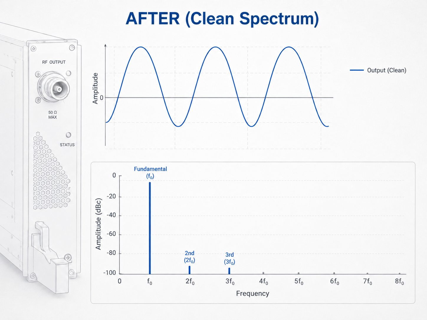
We implement precision non-linear bias alignment across our 30MHz-20GHz platform. This strictly locks carrier spurious emissions down to a clean -60 dBc typical, ensuring absolute spectrum purity during continuous wave output.
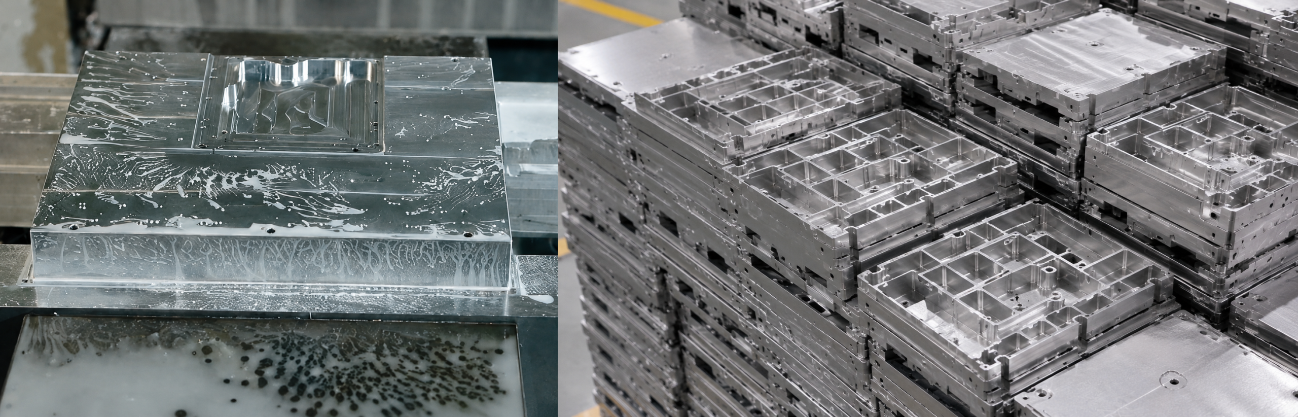
CNC Milled Isolation Cavities
Our in-house CNC processing center mills localized physical isolation barriers within the housing. This eliminates internal electromagnetic crosstalk and feedback loops before they ever reach the output port.
Custom LPF/BPF Integration
We natively embed tailored Low-Pass or Band-Pass Filters directly into the module's output cavity. This aggressively clamps remaining high-order harmonics into strict compliance margins without requiring bulky external filter modules.
Clean amplification guarantees both clinical precision and rapid regulatory clearance.
View Clean RF Output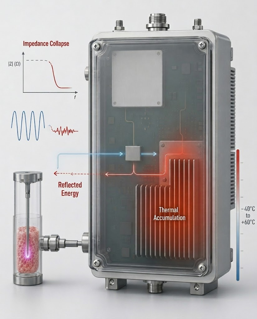
Target Impedance Mismatch and Extreme Internal Thermal Stress
Tissue carbonization or laboratory medium phase change triggers millisecond-scale impedance collapses. Long-term CW operation in sealed enclosure causes rapid thermal accumulation.
Millisecond Impedance Collapse
Tissue desiccation during ablation or gas breakdown in plasma labs triggers severe target impedance collapses within milliseconds, instantly destroying the matched load environment.
Extreme Thermal Accumulation
Long-term Continuous Wave (CW) operation traps massive waste heat inside sealed medical carts, causing internal thermal stress to spike uncontrollably over extended procedures.
Harsh Ambient Environments
Deployments range from chilled labs to harsh ambient temperatures spanning -40°C to +60°C. This extreme thermal delta heavily strains standard cooling and management designs.
Thermal and impedance shocks test the absolute limits of your power generation chain.
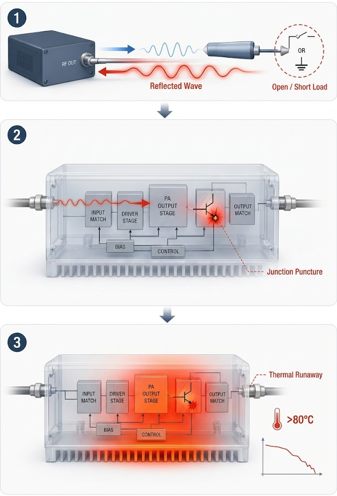
View Hardware Damage RisksReflected Wave Puncture and Catastrophic Thermal Failure
Extreme load mismatch (open/short) reflects hundreds of watts back to the PA, voltage standing wave overlays with DC current puncturing the transistor junction. Thermal accumulation over 80°C triggers irreversible thermal burnout.
Massive Reflected Power Waves
Extreme load mismatches, such as absolute open or short conditions at the applicator, force hundreds of watts of forward power to instantly reverse direction back into the amplifier's output port.
Instant Junction Puncture
The sudden Voltage Standing Wave Ratio (VSWR) spike directly overlays onto the massive DC operating current. Without hardware intervention, this instantly punctures the core transistor junction.
Irreversible Thermal Runaway
Uninterrupted thermal accumulation scaling past 80°C accelerates core degradation. This triggers severe terminal frequency drift and ultimately causes irreversible catastrophic thermal meltdown.
A medical device cannot afford to burn out during a procedure. It must heal itself.
Deploy Self-Healing HardwareMulti-Pin Telemetry and Sub-Microsecond Hardware Self-Healing
Risk detection, alarm output, PA shutdown, and fault reset are handled directly at the hardware layer, avoiding safety delays caused by software lag.
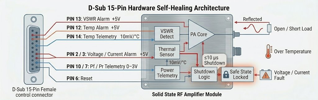
Over VSWR Autolock
Internal hardware detection circuits constantly monitor output integrity. Upon an open or short failure, PIN 13 instantly drives a +5V high-level alarm and executes an immediate PA shutdown within microseconds, preemptively locking the safe state before reflection destroys the core.
Explore VSWR Safety →Over Temperature Interlock
Embedded thermistors actively sense junction temperatures. When heat exceeds 80°C ± 5°C, PIN 12 trips a +5V alert and cuts off the PA. Once cooled back below 70°C ± 5°C, it auto-restarts seamlessly. Concurrently, PIN 14 feeds a 10mV/°C analog output for continuous thermal profiling.
View Thermal Logic →Voltage Clamps & Telemetry
If supply metrics derail past 32V or 31A, PIN 2 and PIN 3 blow a +5V signal to force hard shutdown locks. Meanwhile, PIN 10 and PIN 7 stream 0~3V analog voltages mapping real-time active forward and reversed power, allowing instant field self-healing via PIN 6 resets.
See D-Sub Integration →Medical RF safety compliance must be built on uncompromising hardware-level interlocks.
Explore Integration Standards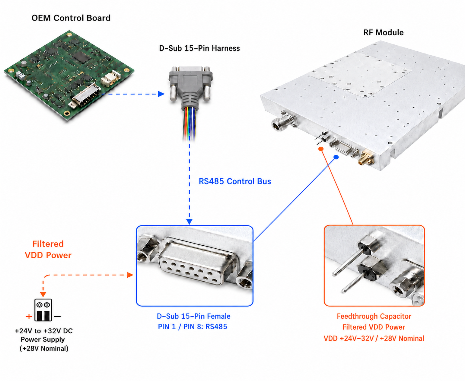
Standardized D-Sub 15-Pin Bus and Filtered Power Input
Medical OEM integration depends on stable, standardized control and power interfaces.
D-Sub 15-Pin & RS485 Integration
Our control interface strictly aligns with a standard D-Sub 15-Pin Female connector. PIN 1 and PIN 8 natively integrate an RS485 serial communication bus, ensuring smooth digital parameter read/write commands for medical mainframes.
Pull-Core Capacitance Input
For the primary VDD power rail, we use high-isolation feedthrough capacitor structures accepting a wide +24V~32V (+28V nominal) input. This filters power-line ripple and reduces high-frequency crosstalk before noise enters the RF module.
Plug-and-Play Consistency
Standardized physical ports reduce integration complexity and supply chain variations. Medical OEMs can easily upgrade, replace, or scale RF nodes without redesigning the entire internal wiring structure.
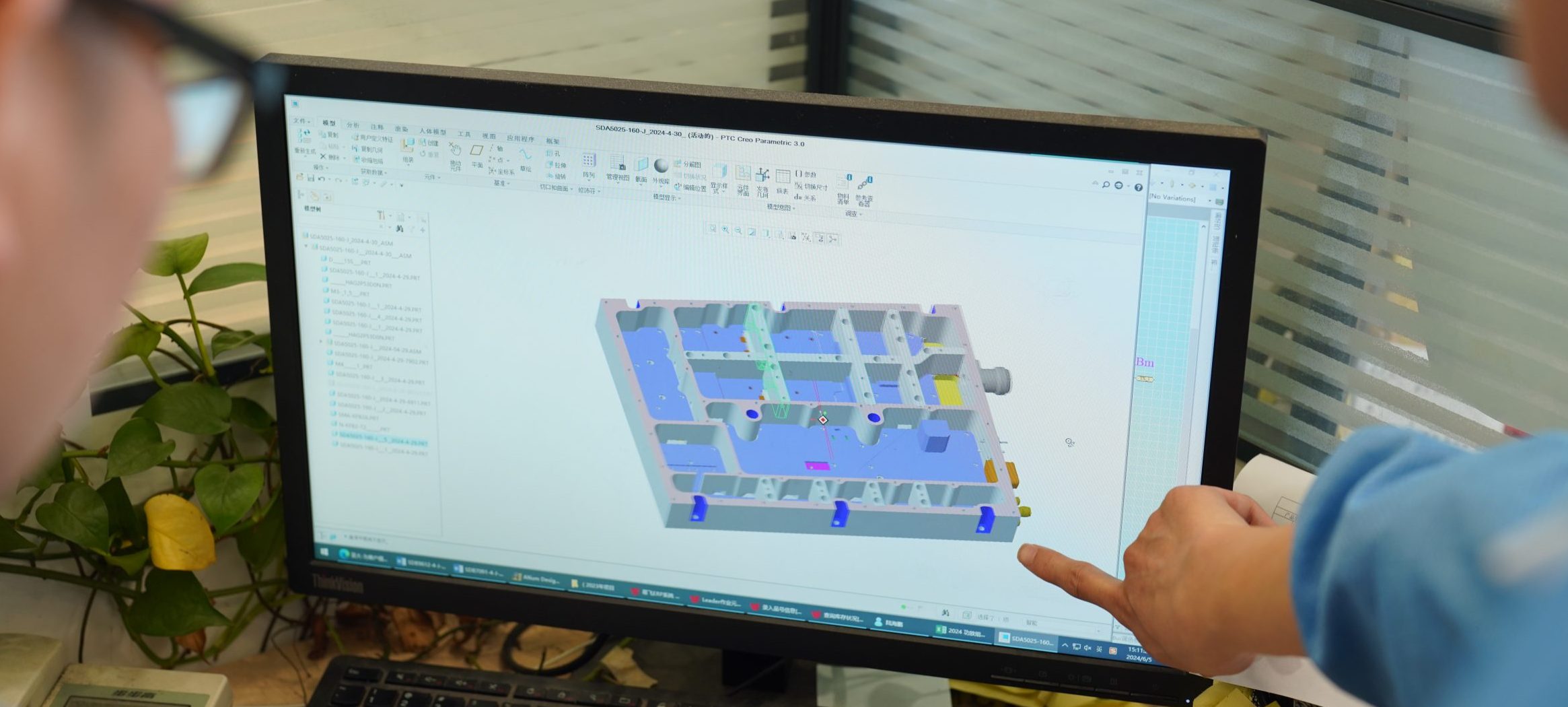
Absolute Mechanical Consistency from Drawing to Mass Assembly
Medical desktop enclosures have highly confined interior spacing. Batch variance is not an option.
Precision CNC Form Factor
Leveraging our in-house CNC machining center, we lock our hardware dimensions strictly into 200 × 158 × 25 mm with a net weight of exactly 1.4 kg, ensuring maximum density for desktop systems.
Micron-Level Tolerance
All structural details, from mounting holes to connector layouts, are strictly processed through digitized milling. This completely eliminates manual assembly deviations and outsourced machining flaws.
Batch Consistency Guarantee
This micron-level tolerance ensures absolute batch consistency across hundreds of mass-produced modules. OEMs can guarantee direct assembly line integration without ever facing footprint mismatches.
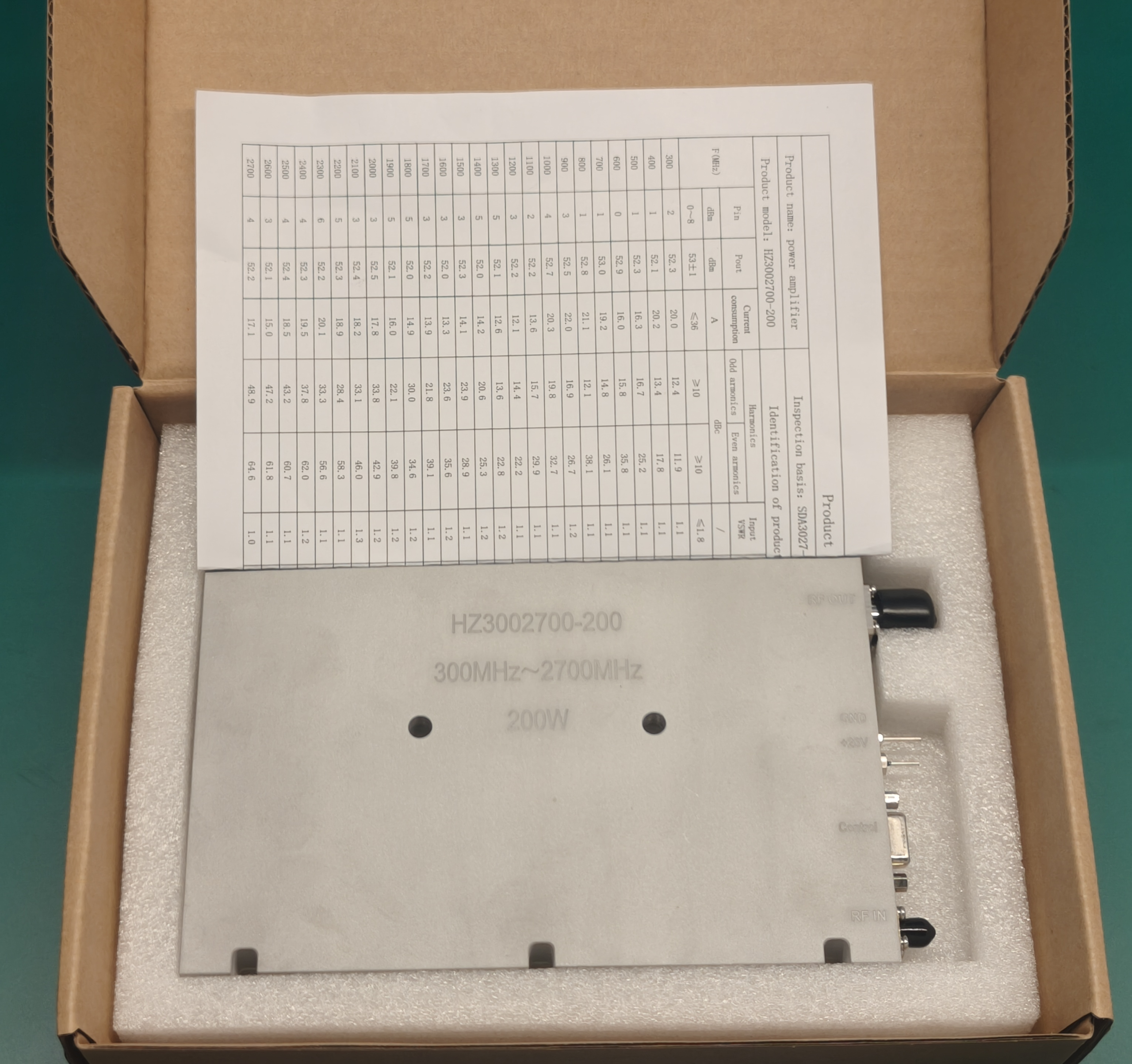
Digital Birth Certificate: End-to-End Compliance Auditing
We abandon generic compliance stamps. Every module arrives with unassailable empirical proof.
Medical and advanced bio-science instruments demand absolute validation tracing. Every single shipped PA and signal source carries an individual Digital Birth Certificate linked to its serial number, supplying an irreplaceable documentation basis for regulatory review.
Individual SN Traceability
Every module is assigned a unique serial number, allowing OEMs to track entire hardware lifecycles and simplify after-market servicing diagnostics.
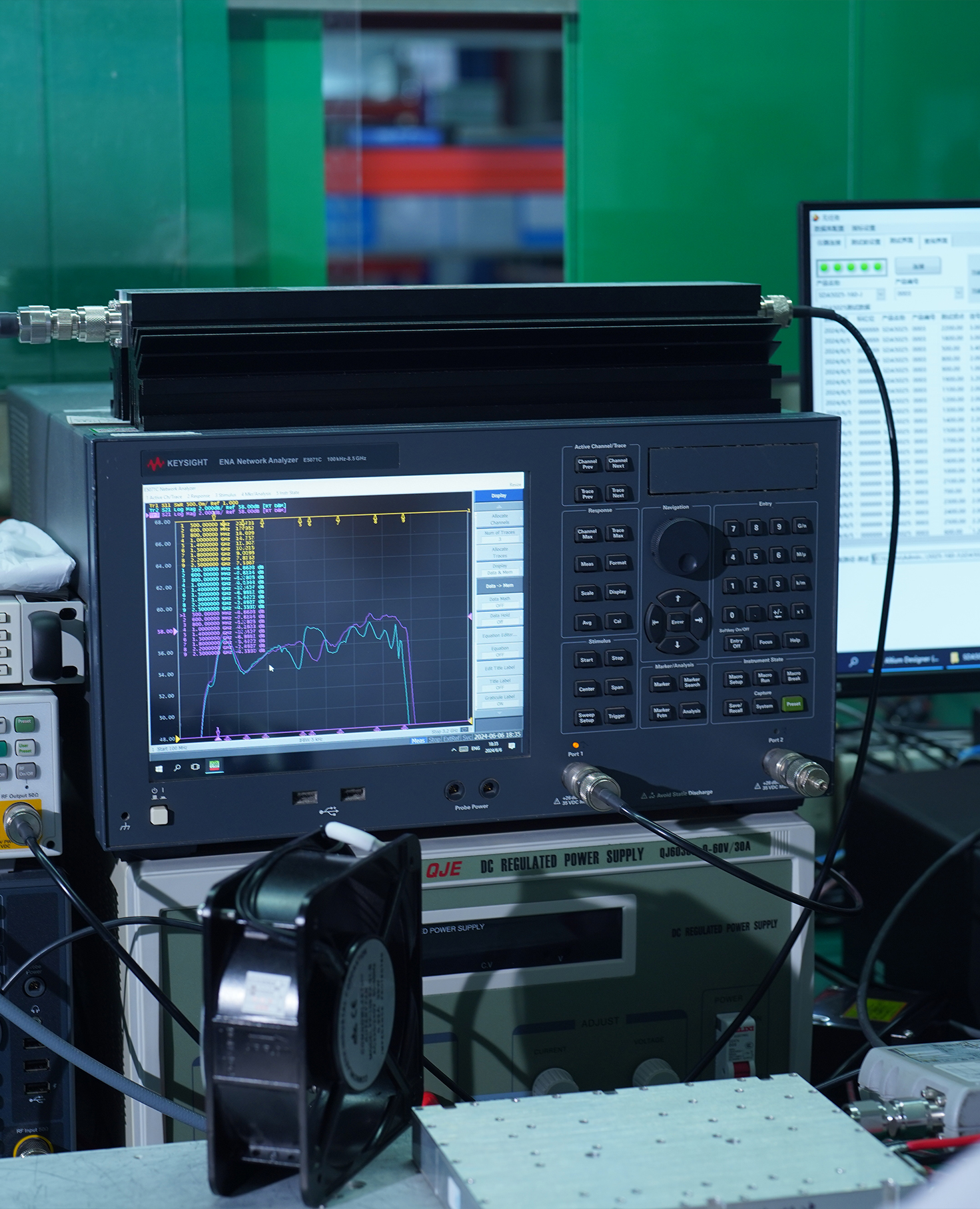
Empirical VNA Data Sweeps
The dossier actively files the module's exact small-signal gain profile, real-world 200W Psat output, -60dBc spurious sweeps, and Input VSWR ≤ 1.8 tracing charts.
Medical EMC Audit Ready
By delivering pre-verified harmonic and distortion data, we drastically streamline your path through stringent medical electrical safety and EMC compliance audits.
Start Your Life Science RF Customization
Direct access to our hardware engineering team. Streamlining your medical compliance path.
Every clinical and laboratory perimeter is different. High-frequency power supply stability, waveform purity, harmonic suppression, and low thermal drift all dictate how your medical RF chain should be engineered.
Share your medical device constraints with us. We evaluate frequency planning, efficiency optimization, and long-term thermal stability before your system integration begins.
30+ Years RF Heritage
Deep factory heritage in high-frequency power supplies and RF amplifier technology.
0.01mm CNC Accuracy
Ensuring absolute hermetic sealing and thermal conductivity management for medical-grade amplifier cavities.
4-Week Rapid Sprint
Empowering highly efficient R&D iteration and compliant prototype delivery for clinical devices.
Strict FDA/EMC Hardening
Engineered exclusively to pass stringent medical electromagnetic compatibility (EMC) compliance.