










Border & Coastal C-UAS: RF Deployment Case Study
Securing coastal perimeters requires coordinated SDR signal control, RF power amplifier modules, wideband antennas, and documented validation. This case study shows how RF SKYPOWER builds a repeatable RF chain for harsh maritime environments.
The workflow supports acceptance review against known low-altitude link profiles and site-specific operating bands.
Thermal behavior is reviewed under high-temperature operating conditions before field acceptance.
CNC enclosures and documented module checks help reduce maintenance uncertainty in coastal environments.

Defending the 200KM Extreme Coastal Frontier
The perimeter faced an unprecedented crisis. Smugglers actively exploited the cover of darkness, utilizing customized 120km/h+ FPV racing drones for illegal maritime drop-offs. Operating precisely at the intersection of high speeds and extreme coastal weather, these incursions turned the sprawling 200-kilometer boundary into a heavily compromised zone.
The "Three Fatal Flaws" Shattering the Shield
Before RF SKYPOWER's engineering review, the deployed commercial-grade jammers showed critical limitations across three interconnected areas: frequency coverage, thermal behavior, and site-level integration.
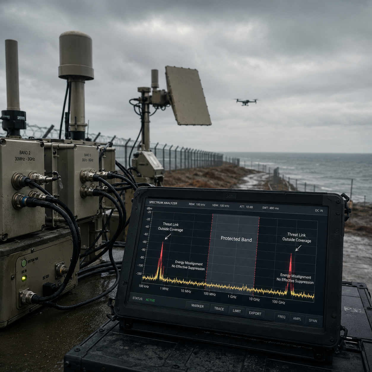
Spectral "Hollowing"
Legacy systems had difficulty tracking non-standard hopping protocols such as ELRS. When RF output was not aligned with the active control link, coverage gaps appeared in the defensive response.
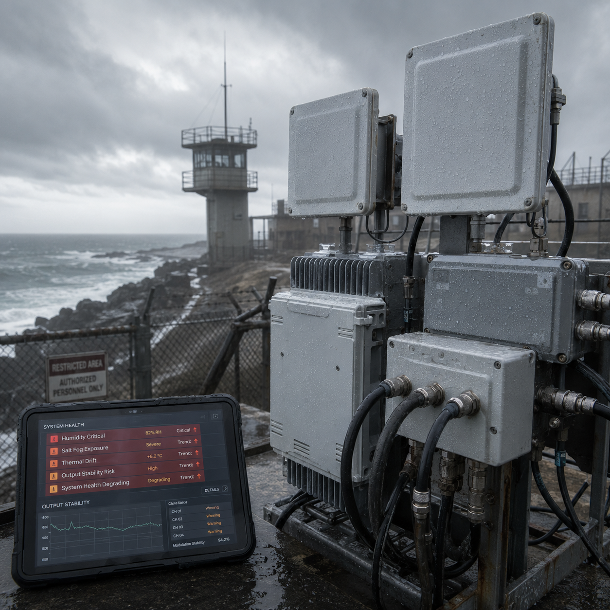
Environmental "Collapse"
Commercial casings showed corrosion risk under coastal salt fog, while limited thermal dissipation reduced confidence in continuous operation under direct 50°C sunlight.
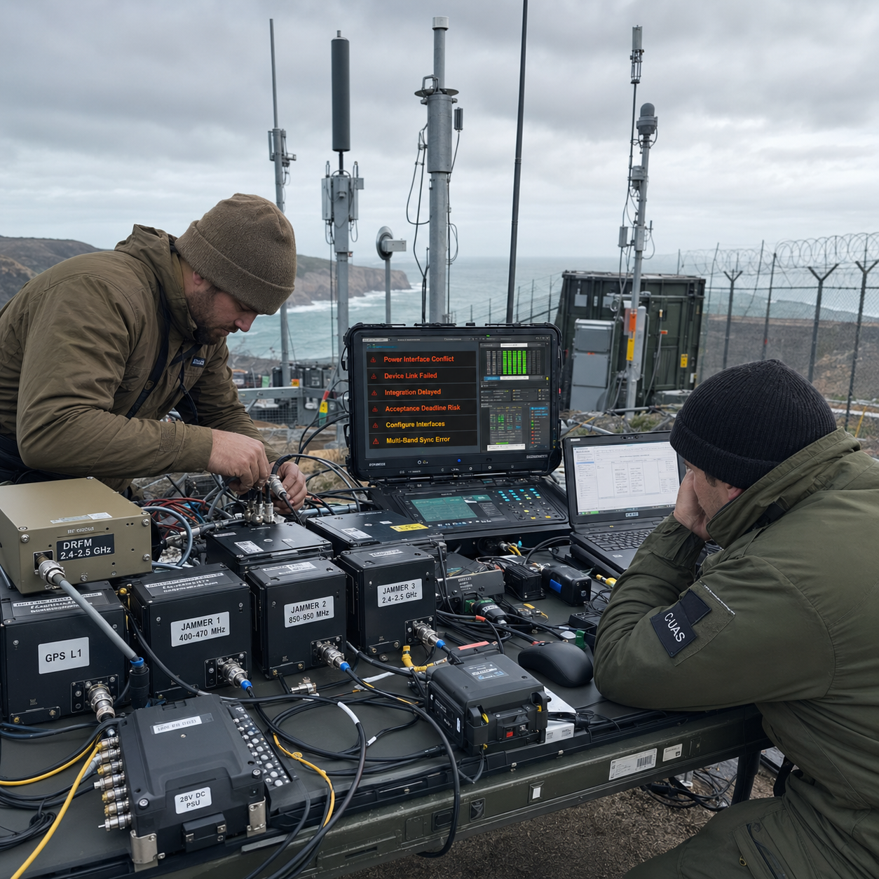
Deployment "Fragmentation"
Stacking multiple single-band antennas on coastal towers increased tower load, feeder complexity, and self-interference risk, creating avoidable integration friction.
The 4-Week "Source Factory" Sprint
To seal the breached coastline before the contract penalty deadline, we eliminated the middlemen. Leveraging our core R&D and in-house manufacturing, we executed an extreme end-to-end rescue sprint—from threat analysis to API integration.

Requirements Lock
We initiated joint technical reviews to map local maritime frequency allocations and freeze API interface specs. Crucially, we locked the thermal envelope parameters to counter the extreme 50°C coastal sun.
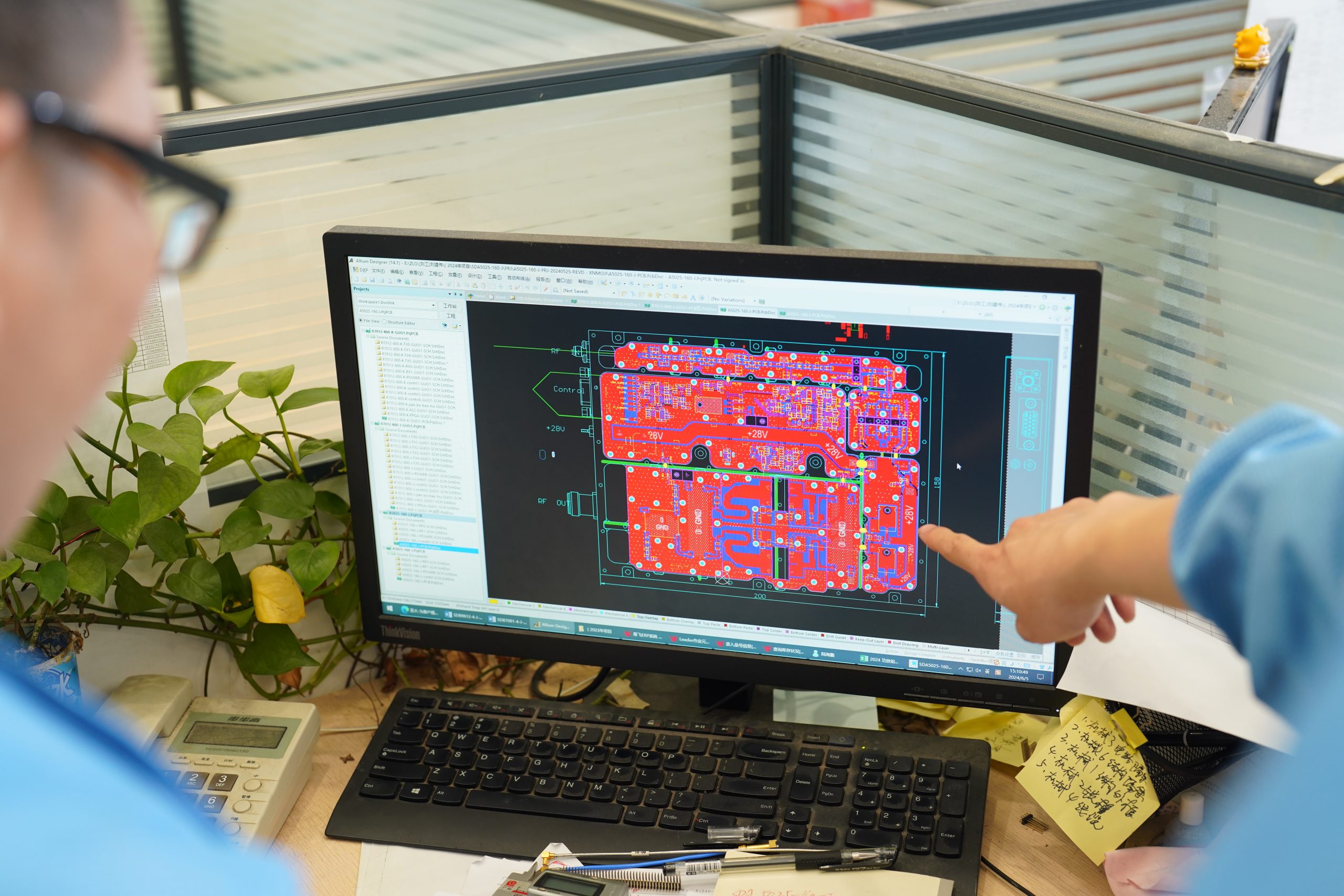
Rapid Prototyping
Leveraging our in-house capabilities, we finalized the SDR schematics and PCB layouts. Concurrent CNC thermal simulations and parallel component preparation helped reduce hardware realization delays.
Build & Validate
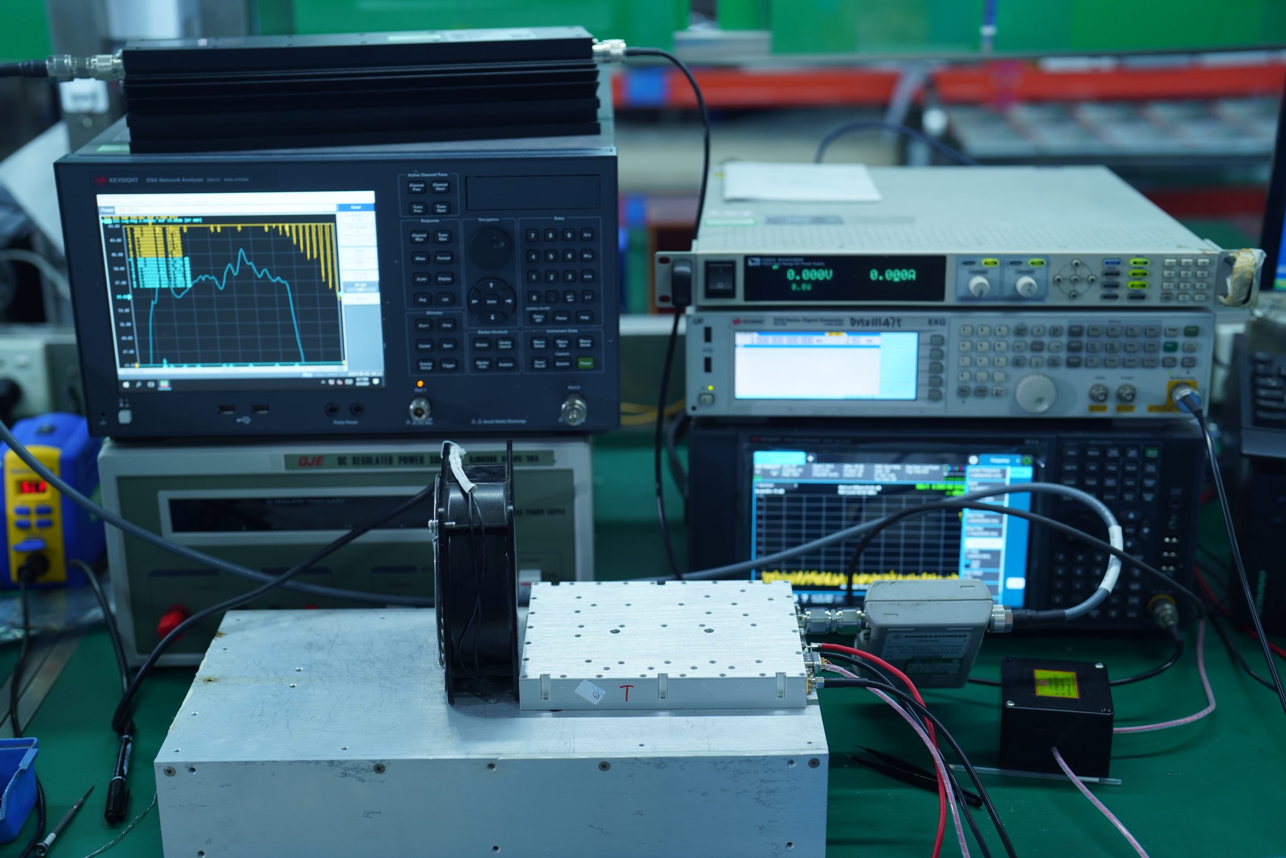
First-article assemblies underwent Environmental Stress Screening (ESS)—including extreme thermal shocks and 12-hour full-load burn-in—followed by rigorous RF vector analysis and remote Factory Acceptance Testing (FAT).

Batch & Ship
"The production run of ruggedized nodes completed RF burn-in before dispatch. The final configuration supported a repeatable hardware baseline for the coastal perimeter deployment."
SDR Intelligence: Protocol-Level Precision Stripping
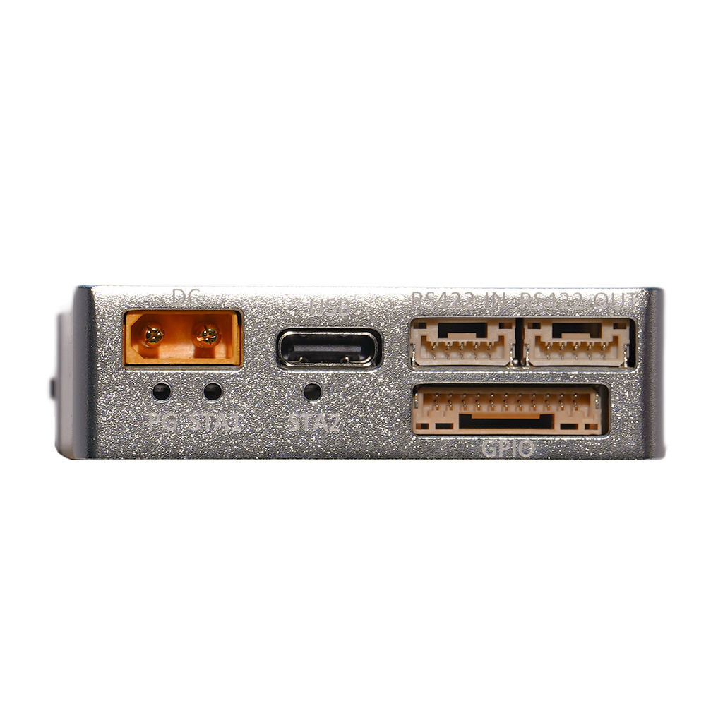
We abandoned the outdated concept of "full-band brute force" jamming. By integrating our Dual-PHY SDR architecture, the system inherently parses and dissects complex hopping protocols (like ELRS and private encrypted links) in real-time. It acts as a spectral scalpel, selectively blasting destructive waveforms exclusively at the hostile signals—resolving the "spectral hollowing" threat while helping reduce impact on local coastal communications
root@sdr-core-v9:~# load_firmware /usb/matrix_update.cs16 > loading firmware... > protocol ELRS_custom isolated > compiling interference matrix [OK]
> Deploying surgical notch algorithms [OK] > System armed. Response profile aligned with selected target bands. root@sdr-core-v9:~# _
Ultra-Broadband Antenna Consolidation
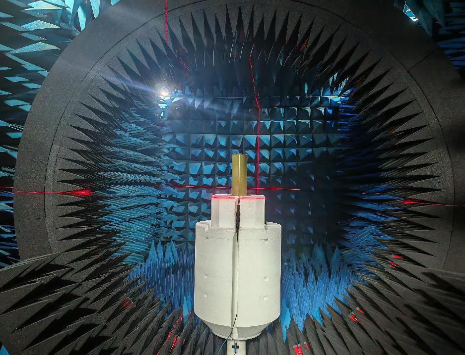
Stacking dozens of single-band antennas creates disastrous wind drag and cabling chaos. We completely reverse this by consolidating extreme frequency spans into a unified, high-weather-resistant architecture.
Resolving Tower Overload
By integrating broadband capabilities into a single radome, one of our antennas effectively replaces up to 12 cluttered legacy antennas.
Aerodynamic Stability
This dramatic consolidation slashes physical wind resistance by over 60%, eliminating the risk of structural tower collapse during severe coastal typhoons while maintaining seamless omni-directional coverage.
CNC Thermal Management
Commercial plastic casings melt under 50°C coastal sun. Overcoming environmental collapse requires designing power output, thermal dissipation, and physical structure as a single cohesive unit. To achieve this, we utilize in-house 5-axis CNC machining to mill our amplifier enclosures from solid blocks of aviation aluminum, creating a massive, unified heatsink perfectly tailored to the RF board topology.
Flawless EMI Shielding
Precision milling ensures seamless cavity closure. This shielding structure helps reduce RF feedback risk into the SDR processing path.
Continuous-Wave Duty Planning
The thermal path is designed to support continuous-wave output targets under high-temperature operating conditions while reducing thermal shutdown risk.
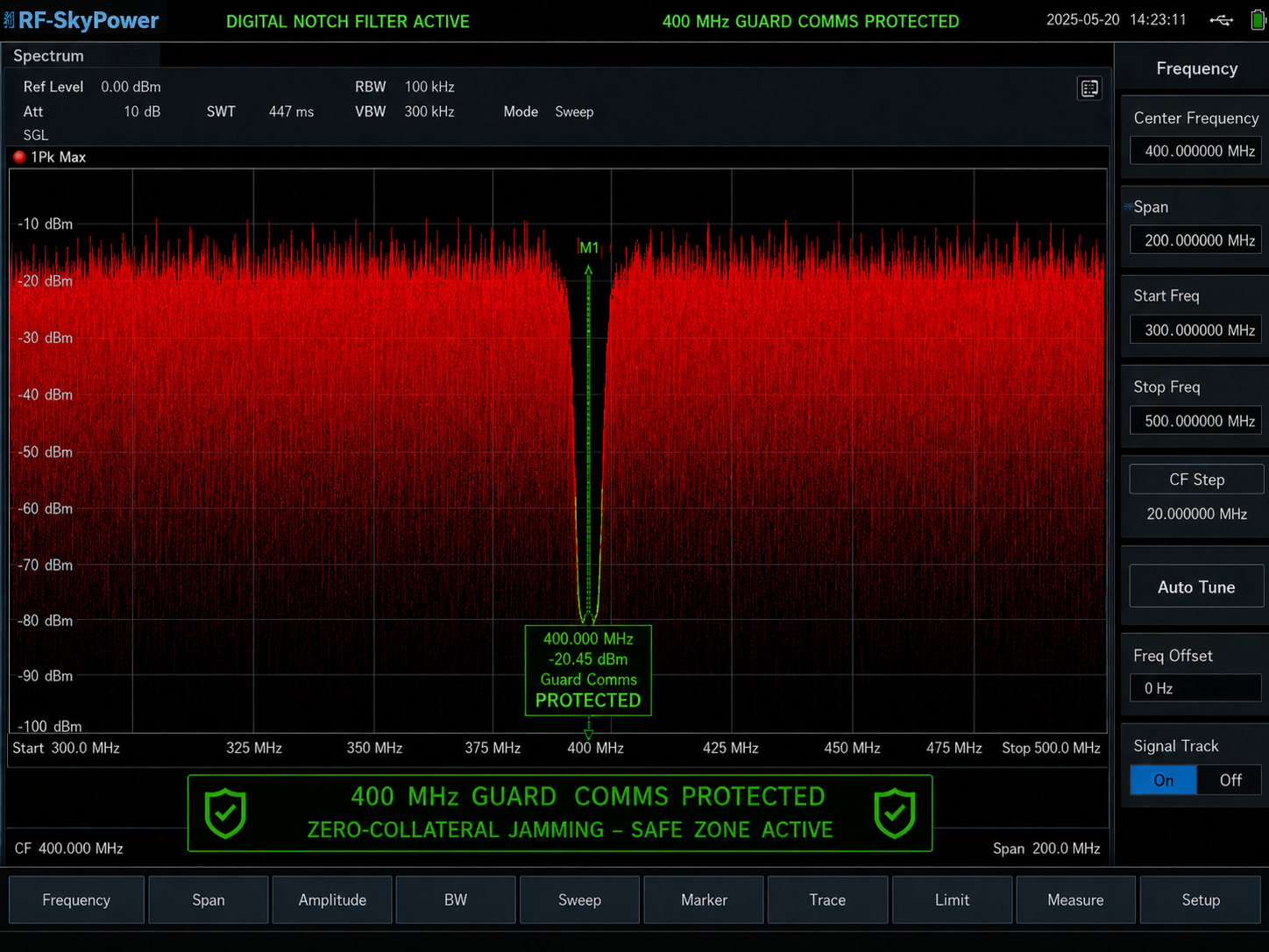
Controlled RF Response in Action
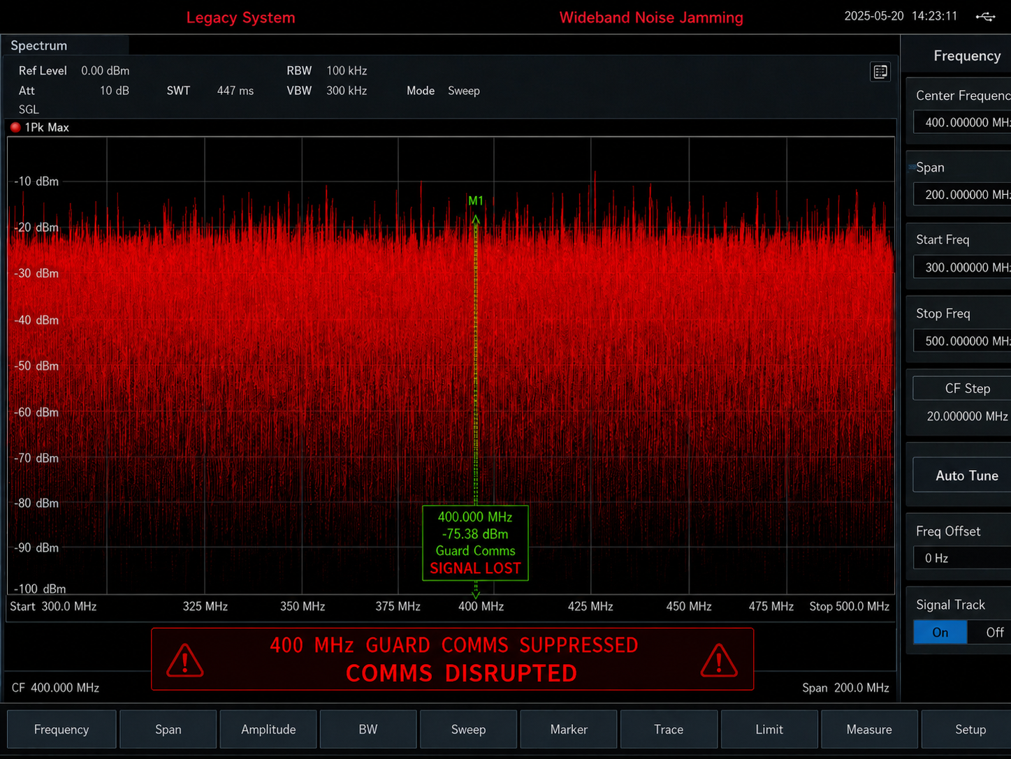
Uncontrolled wideband output can affect guard radios and coastal radar. The SDR-based response is planned around site-specific bands so interference can be directed toward the target link while reducing impact on local communications.
Unified 28V DC Architecture
Long-distance coastal cabling induces severe voltage drops that cripple standard jammers. We eliminated integration fragmentation by standardizing a robust, unified power layer.
28V Alignment Certified
Featuring a 24V-32V wide-input range (28V nominal), the power layer helps reduce voltage-drop risk across long coastal cable runs.
Voltage Stability
Voltage compensation helps reduce power-drop risk across long coastal cable runs and supports more stable RF coverage planning.
Locked BOM Certified
Core power module components are documented for repeatable maintenance planning and long-term procurement review.
The 72-Hour "Rapid Integration"
Closed protocols turn software integration into a delivery black hole. We reversed this by providing standardized AT commands, turning a two-month debugging nightmare into a single weekend's work.
Standard AT Commands
No complex driver compilation. Execute transparent instructions like AT+POWER_ON directly over standard Ethernet interfaces.
Protocol Coordination
Open APIs inherently support seamless embedding into any existing C2 (Command and Control) platform without proprietary lock-ins.
Developer-Level Support
Comprehensive integration manuals shatter the R&D bottleneck, giving your engineering team ultimate deployment control.
> AT+POWER_ON=ALL
[OK] ALL_NODES_ACTIVE_28V
// Assign Surgical Frequency
> AT+TARGET_FREQ=868M, BW=50M
[OK] FREQUENCY_LOCKED
// System Telemetry Handshake
> AT+SYS_STATUS?
[OK] VSWR: 1.12 | TEMP: 45°C
Rejecting the "Black Box": One Report, One Unit
The defense industry is plagued by inflated spec sheets. We rely exclusively on objective instrument data. Every custom module delivered is bound to its unique Serial Number (S/N) and accompanied by its own measured performance report.
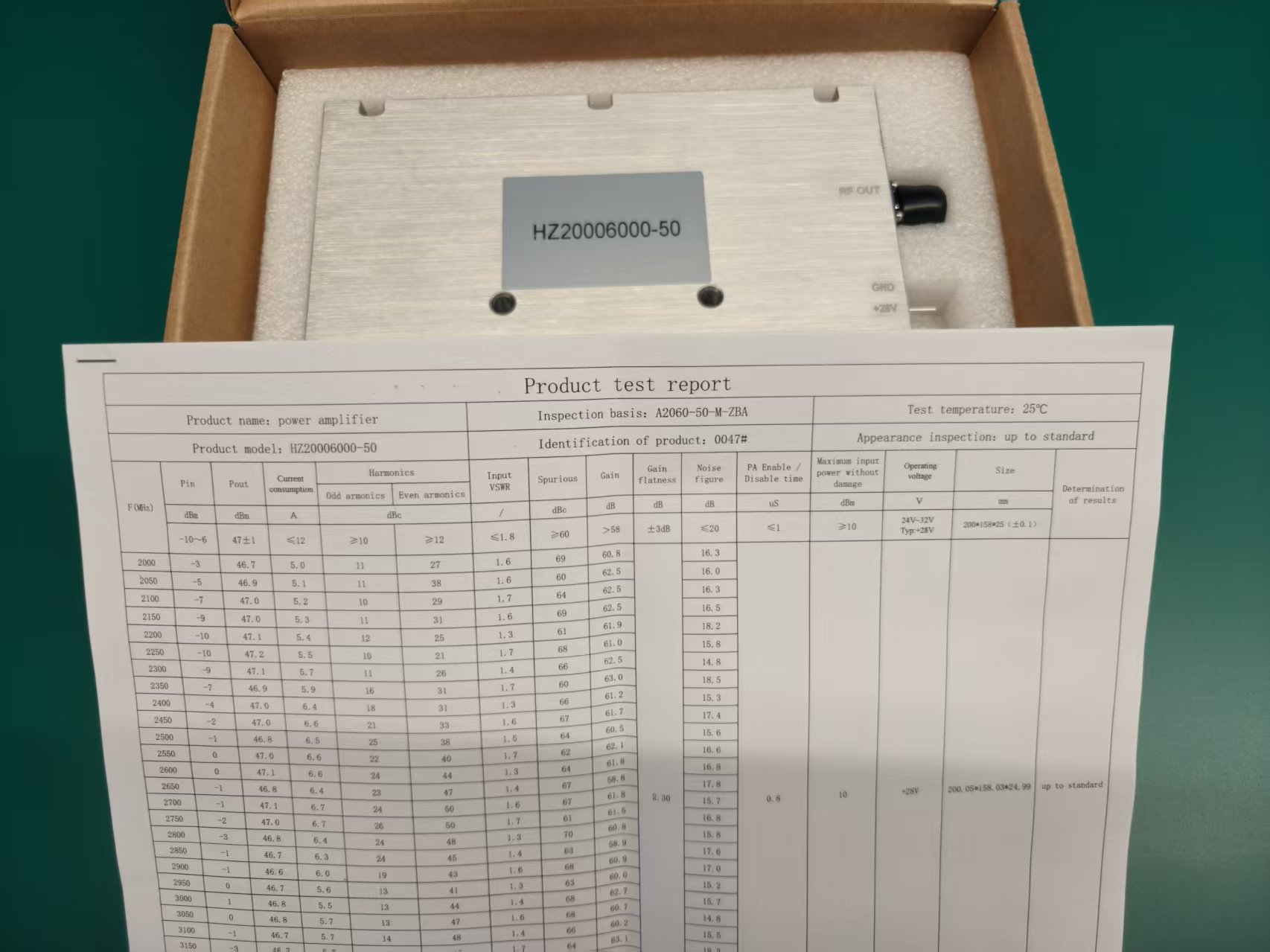
Environmental Stress Screening Lab
Before field delivery, modules go through factory Environmental Stress Screening to review RF output, thermal behavior, vibration response, and operating stability under defined test conditions.
Full-Load Burn-in
Powered by a 60A/800W programmable source, the module maintained continuous 50dBm output under load for 12 hours as part of the RF output stability review.
Vibration Testing
Subjected to 3-axis random vibration sweeps at 15-2000Hz (PSD=0.04g²/Hz) for 2 hours per axis to review transport and coastal wind-related stress response.
Extreme Temp Operations
Endured extreme thermal shocks from -55°C to +85°C, including a 48-hour +85°C bake followed by powered operation at +60°C, ensuring circuit behavior under tropical coastal conditions
VNA Vector Analysis
Every RF cavity undergoes S-parameter sweeping to review impedance matching consistency.
Field Outcome, Stated Conservatively
The result is presented as a practical engineering baseline rather than an exaggerated performance claim: less integration uncertainty, clearer validation evidence, and a repeatable path for later coastal sites.
Starting point
Fragmented RF paths, multiple antenna loads, unclear thermal margin, and limited unit-level evidence.
Final baseline
Consolidated RF architecture, documented module checks, and a repeatable configuration for later coastal sites.
Validation language
Performance claims are tied to acceptance testing, RF output records, and environmental screening instead of overstated claims.
Integrator value
Lower integration uncertainty, clearer service visibility, and stronger documentation for procurement review.
Start Your Customization Sprint
Bypass the sales pitch. Submit your RF parameters below, and our core engineering team will provide a precise technical alignment within 24 hours.
E2E Technical Alignment
When you partner with RF SKYPOWER, you communicate directly with the core engineering team designing the underlying RF architecture.
-
Factory-Based Manufacturing In-house R&D and specialized CNC/SMT lines ensure rigid quality control.
-
Pre-Verified Ecosystem Procure compatible RF modules, antennas, and SDR sources to eliminate integration friction.
-
Documented Quality Review Every unit undergoes rigorous MIL-STD burn-in and calibration before shipment.
The Skypower Advantage
30+ Years RF Heritage
Deep technical accumulation from a true direct source manufacturer.
0.01mm Precision SMT
Documented review of signal phase and amplitude consistency.
4-Week Integration Sprint
High-speed delivery from custom architecture to physical prototype.
100+ Countries Deployed
Battle-proven reliability in extreme global defense environments.