


Rescuing a Medical RF Generator Before OEM Validation Failure
A medical device OEM was preparing a compact RF generator for prototype validation. The original RF core showed unstable pulsed output, harmonic leakage, internal chassis loss, and rising thermal drift inside the sealed enclosure. Our factory replaced the unstable RF chain with a controlled solid-state RF energy core built for clean spectrum, fast pulse response, hardware protection, and standardized OEM integration.
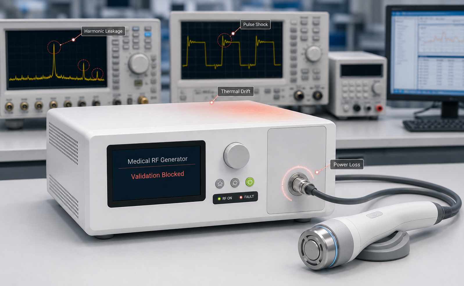
Medical RF Generator Validation Was Blocked
During internal validation, the customer’s prototype generator showed four simultaneous failure symptoms: pulse-edge current shock at PA enable, harmonic leakage around the intended RF output, measurable power loss before the front-panel output, and continuous heat accumulation inside the sealed chassis. The issue was no longer a component replacement problem. It required a controlled RF core redesign.
Before redesigning the entire generator, the OEM needed to identify whether the RF core itself could be stabilized.
View the Controlled Replacement PlanWhy the First Medical RF Prototype Could Not Move Forward
TThe first prototype could generate RF power, but it could not keep that power stable, clean, and deliverable inside a compact medical generator chassis.
Pulse Enable Stress Was Ignored
The original design focused solely on rapid PA toggling, ignoring the massive transient shocks along the bias circuit during dense PWM operations. This continuous bombardment degraded the energy chain, risking unpredictable drops in validation performance.
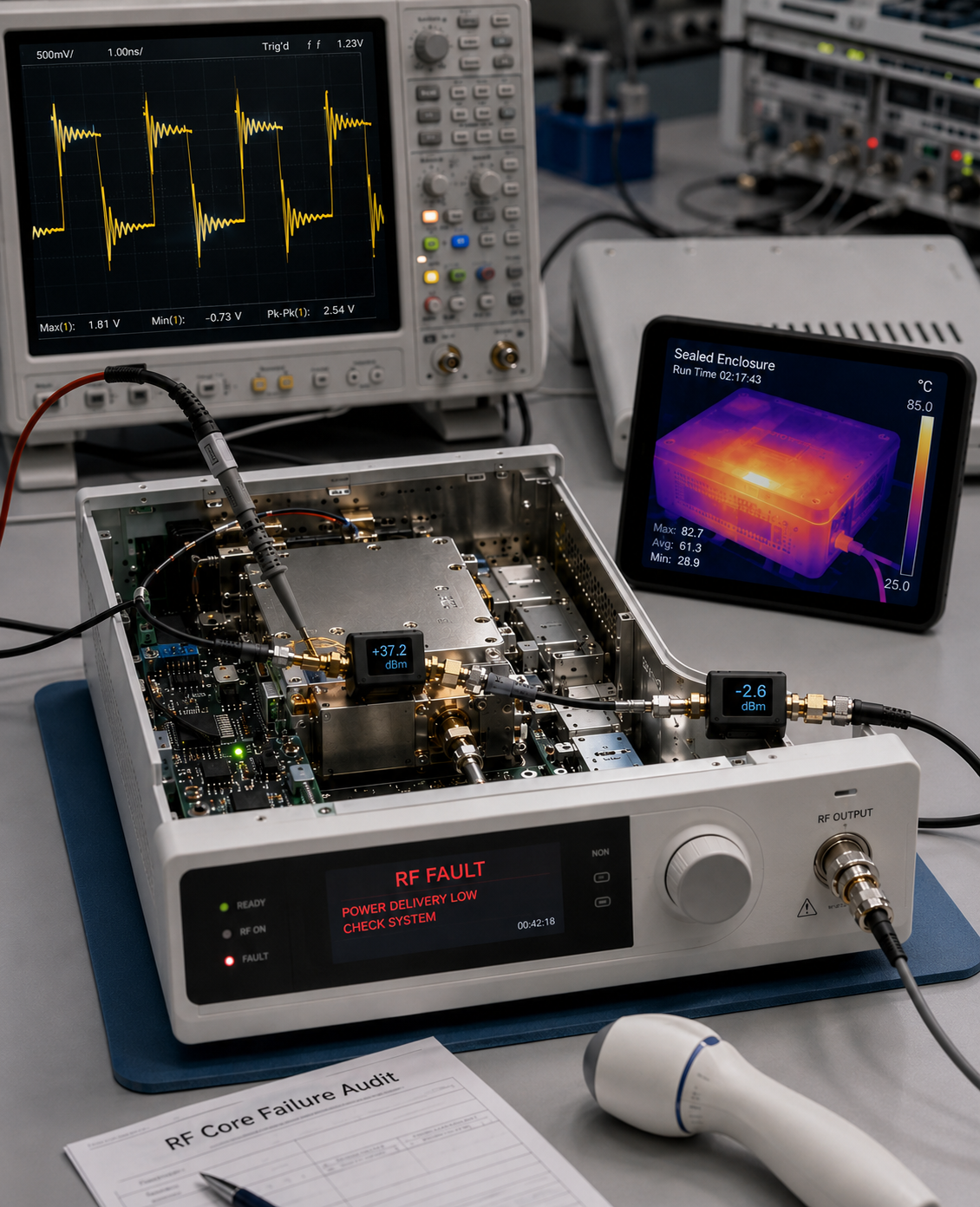
RF Power Was Lost Inside the Chassis
Raw PA output looked sufficient during bench testing. But after isolators, coaxial transitions, couplers, and front-panel routing, the delivered output dropped below the OEM target.
Heat Built Up in the Sealed Enclosure
The legacy core passed short open-bench tests, but failed under the airflow limits of a clinical desktop enclosure. Heat accumulation caused drift and triggered protection behavior.
Before redesigning the entire generator, the OEM needed to identify whether the RF core itself could be stabilized.
View the Controlled Replacement PlanControlled Replacement Matrix:
Turning RF Failure Findings Into Engineering Actions
Each audit finding was mapped to a specific RF-core requirement, factory response, and validation method — allowing the OEM to rebuild the unstable RF section without redesigning the entire medical generator.
The replacement plan focused on preserving the OEM’s system architecture while rebuilding the unstable RF energy chain.
See Core Solution 1Rebuilding the Pulse-Controlled RF Output Path
The original PA could produce power, but the generator could not deliver it repeatably. We rebuilt the RF path around solid-state pulse control, gain compensation, and front-panel output verification.
Solid-State PA Switching
The enable path was rebuilt for controlled PWM operation. Fast PA switching remained available, but the bias circuit was no longer exposed to unmanaged pulse-edge stress.
Fast switching became controlled switching.
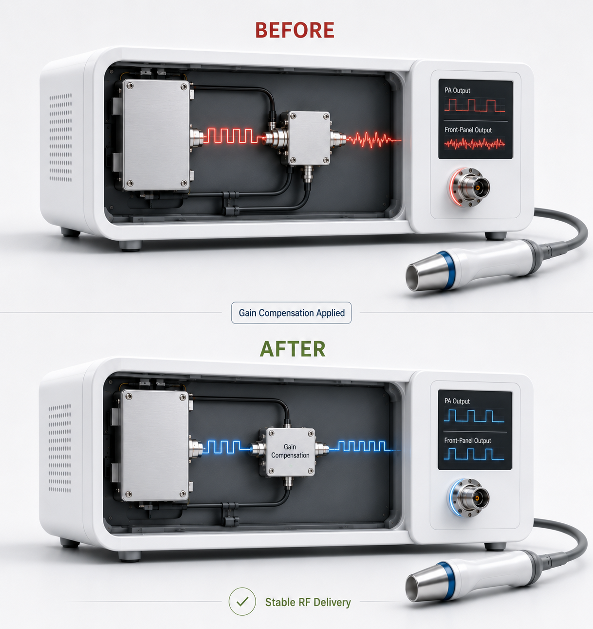
Gain Compensation for RF Path Loss
The RF output was calibrated across the full internal path, not only at the PA node. Gain correction helped recover the power lost through cables, couplers, and front-panel routing.
The target was repeatable generator output, not maximum PA output.
Verified Front-Panel Delivery
The RF chain was treated as one delivery system from PA output to applicator connector. Final validation was based on the front-panel output point the OEM actually uses.
Every RF transition became part of the delivery path.
Need a pulse-controlled RF core for a compact medical generator? Review our solid-state RF module platform before moving to protection logic.
View RF Core ModulesFail-Safe RF Core Protection Under Mismatch and Heat
Once the output path was stabilized, the next risk was survival under abnormal load. We added hardware-level protection for VSWR, reflected power, temperature, voltage, current, shutdown, alarm feedback, and reset logic — so the OEM controller could react before the RF core was damaged.
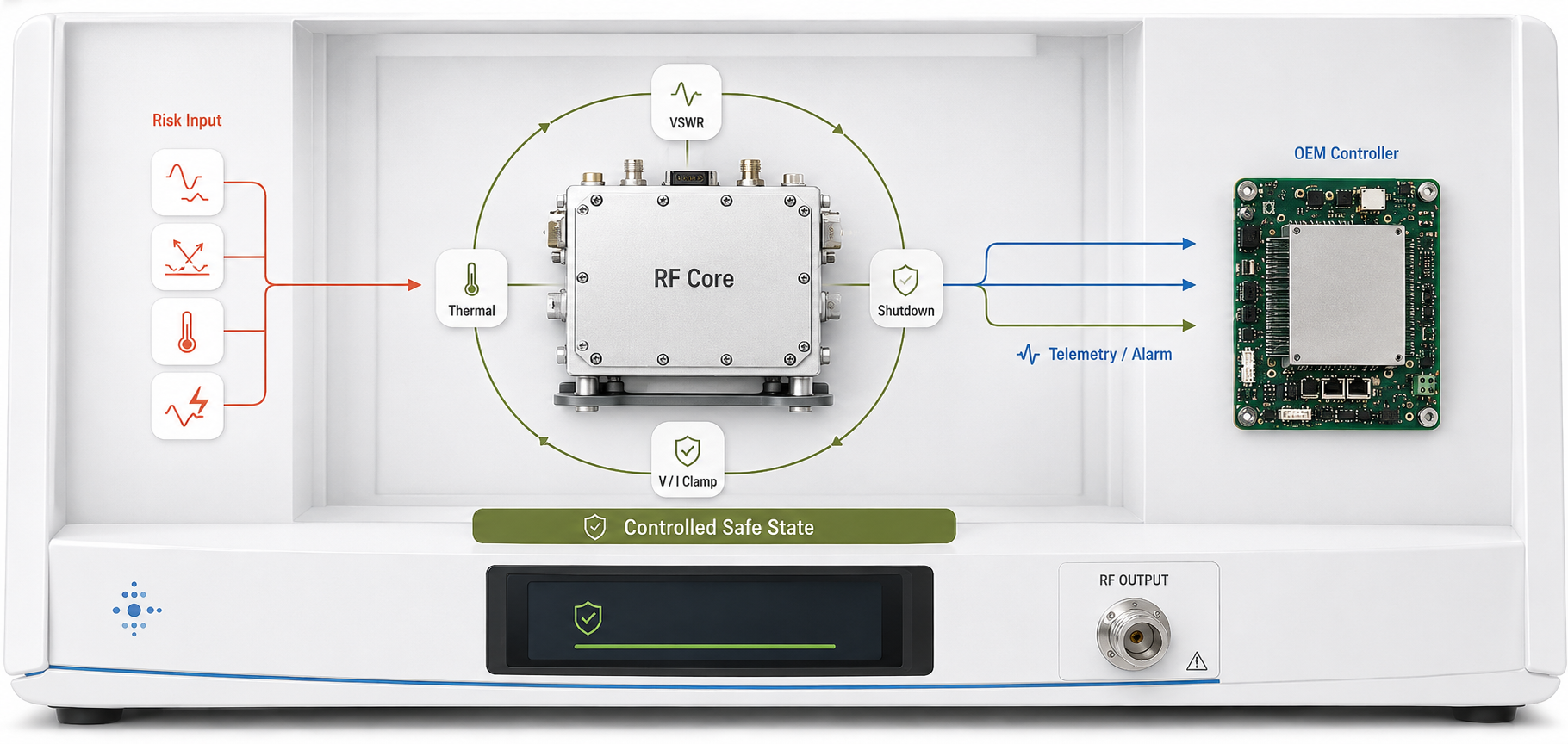
VSWR Autolock for Load Mismatch
Open-load, short-load, and applicator mismatch events can send reflected energy back into the PA stage. The replacement RF core used hardware-level VSWR detection to trigger alarm and shutdown before reflected power could escalate into device failure.
Thermal Interlock for Sealed Medical Enclosures
The customer’s desktop generator had limited airflow and compact internal spacing. Thermal monitoring and interlock logic allowed the RF core to enter a safe state under heat accumulation, instead of drifting silently during long operation.
Voltage / Current Telemetry for OEM Control
Forward power, reflected power, voltage, current, temperature, alarm, shutdown, and reset states were exposed to the OEM controller. The RF section became a readable subsystem instead of a blind amplifier block.
Second objective: make the RF core enter a controlled safe state under mismatch, thermal rise, or unstable supply conditions.
Calculate Thermal & Size FitStandardizing the RF Core for OEM Control Integration
The OEM did not want to redesign the whole generator controller. We standardized the RF core interface so the existing mainboard could control gain, read alarm states, receive telemetry, and manage shutdown/reset logic through a clean production-ready harness.
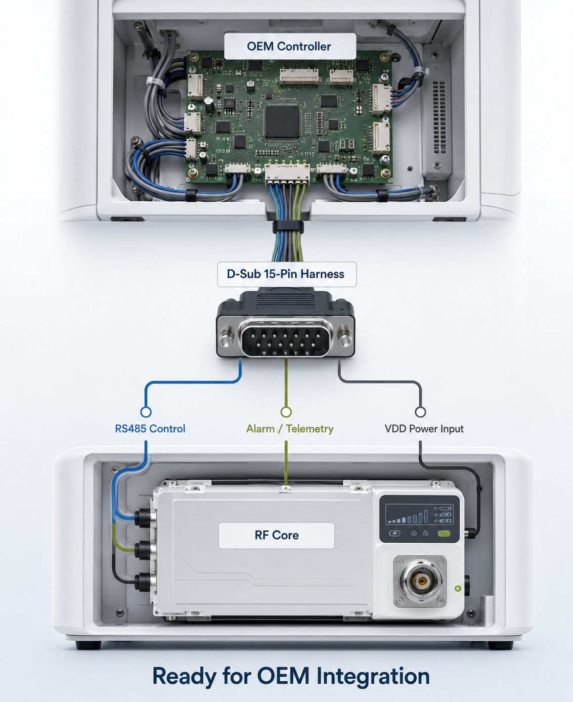
D-Sub 15-Pin Control Harness
Enable, alarm, reset, telemetry, and control signals were organized into a defined D-Sub harness. This reduced prototype wiring uncertainty and gave the OEM a repeatable interface for future assembly.
The RF core became a defined subsystem, not a loose collection of signals.
RS485 / Modbus Control Path
Serial communication allowed the OEM controller to read RF core status and adjust operating parameters without rebuilding the main control architecture.
The OEM controller could command the RF section instead of only powering it.
Separated Power and Signal Routing
VDD power input, RF output, and control communication were routed as separate paths. The internal wiring became cleaner, easier to service, and better prepared for pilot production.
The wiring was redesigned for production serviceability, not just prototype function.
Third objective: let the OEM keep its controller while gaining command, alarm, telemetry, and reset access to the RF core.
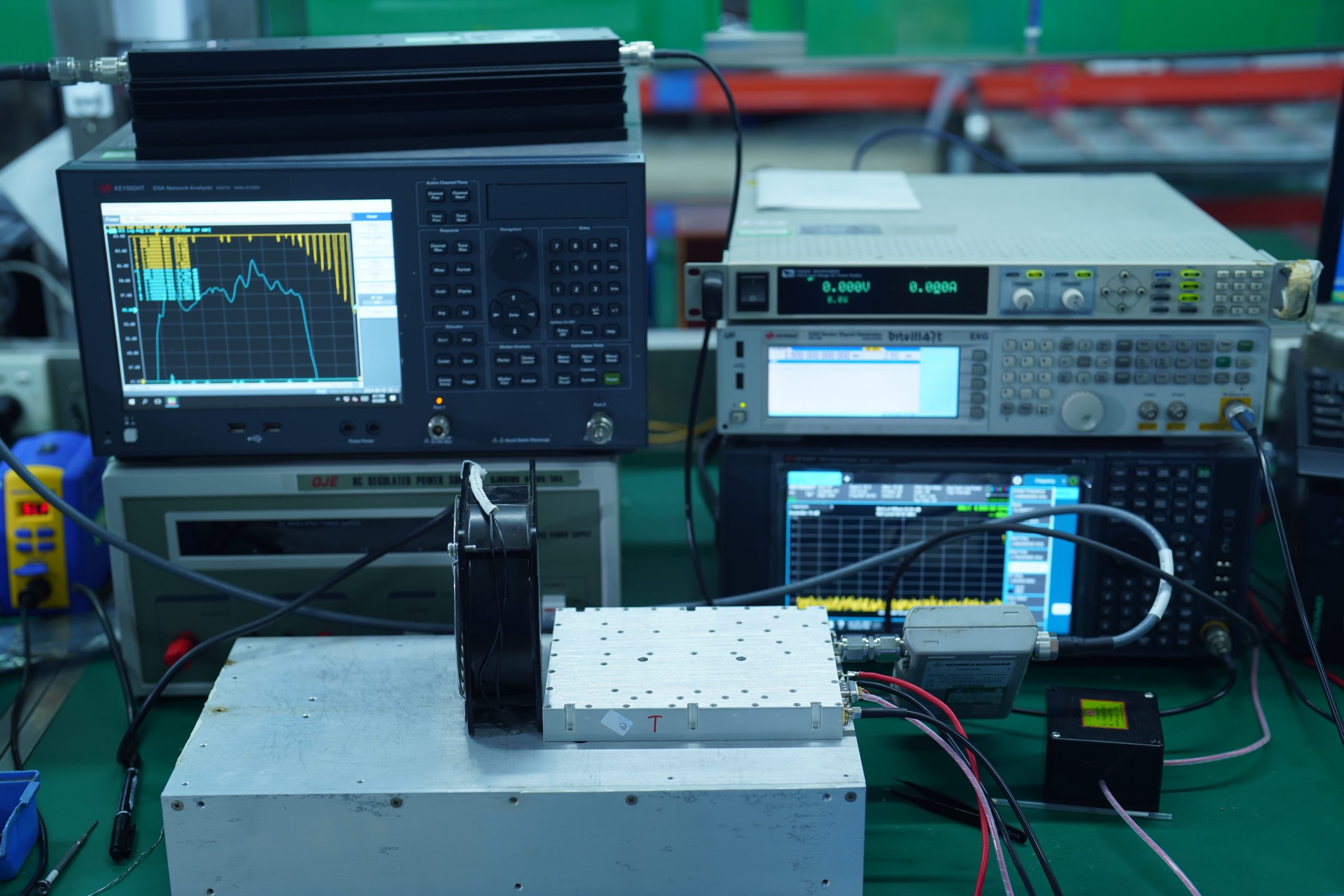
View Signal VerificationProving Clean Spectrum and Stable Pulsed Output
After the replacement RF core was installed, the first acceptance step was objective measurement. The OEM reviewed pulse behavior, spectrum cleanliness, and front-panel output delivery before moving the prototype into the next validation phase.

Pulse Edge Stability
The pulsed RF output was checked on the oscilloscope after the new core was installed. Rise and fall behavior became repeatable, with reduced overshoot and ringing during enable / disable operation.
Harmonic Suppression
Spectrum review confirmed that harmonic and spurious peaks were reduced around the intended RF output. This gave the OEM a cleaner signal baseline for further EMC and system validation.
Front-Panel Output Confirmation
Output was verified at the generator connector, not only at the PA node. This confirmed that the corrected RF path could deliver repeatable power at the point used by the OEM system.
The replacement RF core was accepted through measured waveform, spectrum, and output-path evidence — not by claim.
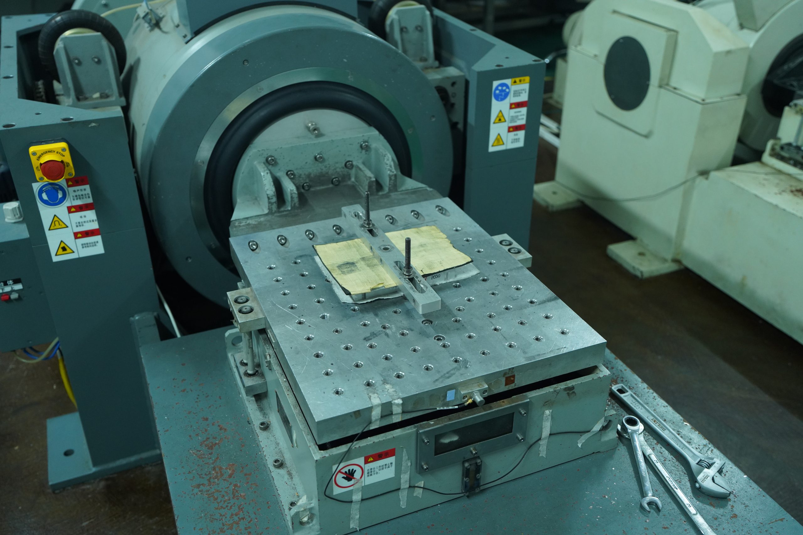
View Chassis ValidationValidating the RF Core Inside the Real Medical Chassis
After signal verification, the RF core was checked inside the customer’s real generator chassis. Mounting, cable routing, thermal contact, airflow limits, and front-panel output geometry were verified as part of the physical system.
Mechanical Fit and Mounting Interface
The RF core was checked against the customer’s chassis space, mounting holes, connector direction, and service clearance. The goal was to fit the existing generator structure without forcing a full mechanical redesign.
The RF core had to fit the generator, not force the generator to be rebuilt.
Thermal Contact and Heat Path
Thermal contact was verified through the module base, chassis contact surface, and airflow-limited enclosure condition. The focus was to confirm that heat could leave the RF core under real generator constraints.
Thermal performance was verified through the customer’s real enclosure constraints.
Cable Routing and Serviceability
RF coaxial lines, VDD power wiring, and control harnesses were routed as separate serviceable paths. This reduced layout uncertainty and made the prototype easier to repeat in later builds.
A stable prototype must also become a repeatable assembly.

This phase confirmed that the RF repair was not only electrically correct, but usable inside the customer’s real medical generator chassis.
View Factory ValidationFactory Burn-In and Unit-Level Traceability Before Delivery
Before release for OEM reintegration, each RF core passed factory-side validation covering power output, spectrum review, thermal behavior, protection response, burn-in records, and serial-number traceability.
Check
Test
Review
Burn-In
Test
Released
Full-Load Burn-In
Each RF core was operated under defined load and duty conditions before release. Burn-in helped screen early instability, thermal drift, and output variation before the unit reached the OEM bench.
Spectrum / Power / Thermal Record
Factory records captured output power, spectrum behavior, thermal response, and protection status. The acceptance basis moved from verbal confirmation to measured evidence.
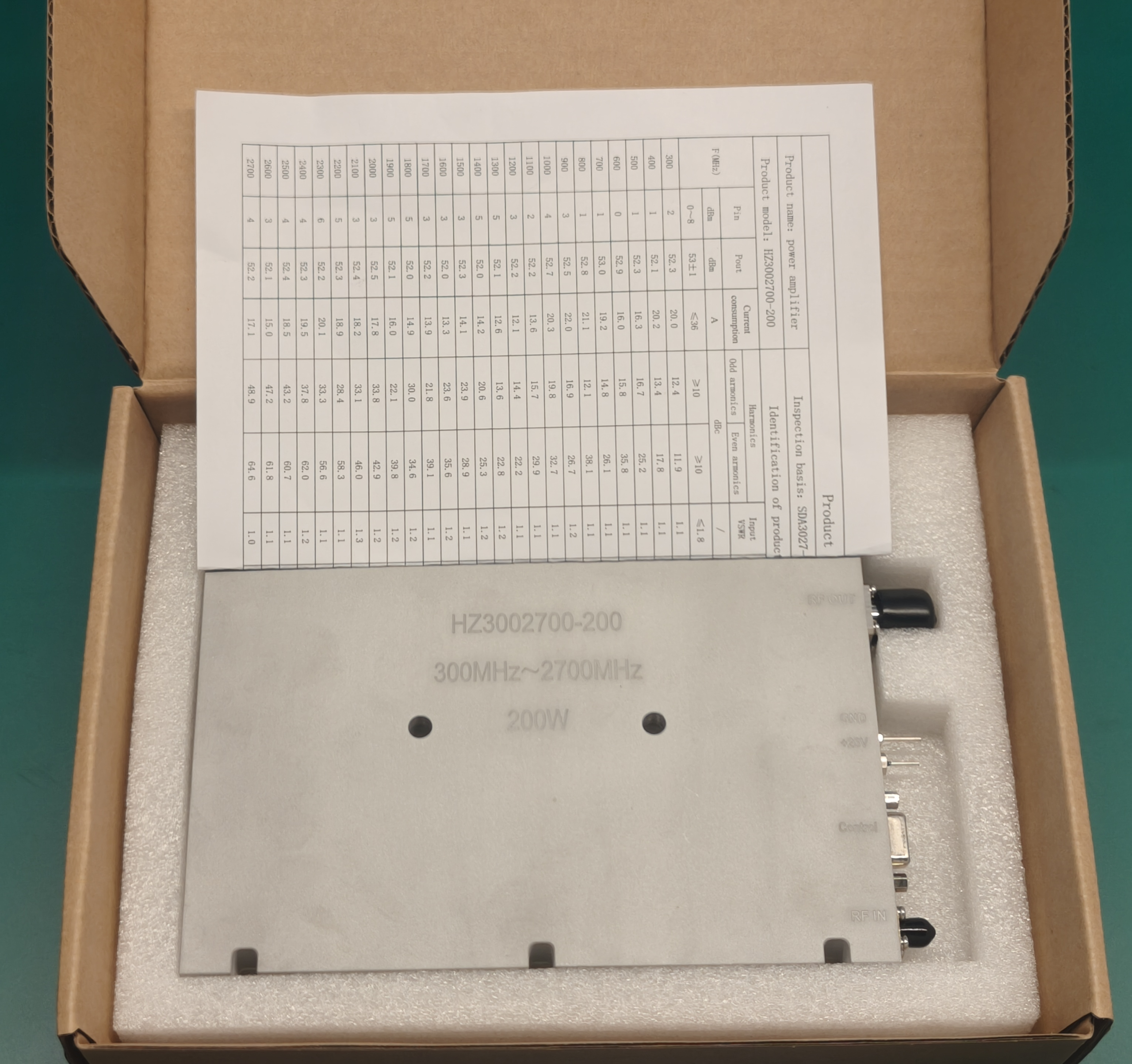
Serial Number Traceability
Each delivered RF core was linked to a serial-number-based test record, allowing the OEM to trace configuration, validation data, and factory release status for each unit.
Every customized RF core must match real enclosure limits, heat paths, and duty-cycle conditions before production validation begins.
Check Your RF Core FitMeasured Results After RF Core Replacement
After the controlled RF-core replacement, the prototype moved from unstable bench behavior to a measurable, protected, and integration-ready RF subsystem. Final acceptance was based on waveform, spectrum, output delivery, protection logic, chassis fit, and factory traceability.
Pulsed RF Control Restored
Stable PA enable / disable behavior under PWM operation, reducing pulse-edge instability during prototype validation.
Front-Panel Output Stabilized
The RF path was corrected from PA output to front-panel output, reducing hidden internal loss and improving repeatable energy delivery.
Harmonic Leakage Suppressed
Measured spectrum review confirmed reduced harmonic and spurious peaks around the intended RF output.
Protection Logic Activated
VSWR, reflected power, thermal, voltage, current, alarm, shutdown, and reset logic were integrated into the OEM control architecture.
Chassis-Level Fit Confirmed
Mounting, cable routing, thermal contact, and front-panel RF geometry were verified inside the customer’s real generator chassis.
Traceable Delivery Package Released
Each RF core was released with factory-side validation records covering output, spectrum, thermal behavior, and protection response.
Have a similar prototype failure? Submit your RF chain constraints before redesigning the entire generator.
Submit Similar Case for ReviewFrom One Generator Rescue to Multiple Medical RF Platforms
The CleanPulse project created more than a repaired prototype. It established a reusable RF energy-core architecture that can be adapted across medical and life-science platforms requiring clean spectrum, pulsed control, protected output, and OEM-level command access.
RF Diathermy Generator
Requires stable CW / pulsed RF output, predictable front-panel energy delivery, and thermal stability inside compact desktop equipment.
Electrosurgery Generator
Requires fast pulse response, clean switching behavior, and protection against load mismatch during cutting or coagulation modes.
Microwave Ablation Platform
Requires high-density RF power, reflected-power protection, thermal control, and consistent output under variable tissue-load conditions.
Laboratory Plasma Equipment
Requires stable RF delivery, impedance tolerance, long-duration operation, and controllable interface logic for research platforms.
OEM Platform Upgrade
Legacy generators can be upgraded from unstable amplifier sections to standardized RF-core subsystems without redesigning the entire device.
The same replacement logic can be adapted to different frequency, power, pulse, and thermal constraints.
Check Application FitFrom Prototype Rescue to Production RF Core
The CleanPulse case was structured as more than a one-time repair. After the unstable RF section was replaced and verified, the same architecture could support pilot builds, production configuration, and future platform upgrades.
A successful RF rescue should not end at one prototype. It should become a reusable production architecture.
Plan Your RF LifecycleFailure Audit
Identify why the first RF chain failed.
Controlled Replacement
Replace the unstable RF section without rebuilding the full generator.
Prototype Re-Validation
Verify signal, spectrum, chassis, and protection behavior.
Pilot Build Support
Standardize wiring, reports, and configuration for pilot production.
Platform Upgrade
Extend the architecture to future medical RF platforms.
Before Rebuilding the Whole Generator, Audit the RF Core First
If your prototype shows unstable pulsed output, harmonic leakage, front-panel power drop, reflected-power alarms, or thermal drift, the issue may not require a full generator redesign. A controlled RF-core audit can identify whether the failure comes from switching behavior, RF path loss, mismatch protection, thermal design, or interface architecture.
Submit Your Medical RF Core Evaluation
Share your generator constraints, RF output targets, load conditions, control interface, and thermal limits. Our engineering team will evaluate whether your prototype requires RF-core replacement, output-path correction, protection logic redesign, or a fully customized RF energy subsystem.
What Our Engineers Review
RF Chain Failure Source
Whether the problem comes from PA behavior, RF path loss, load mismatch, or control timing.
Output Correction Feasibility
Whether front-panel output can be restored through RF-core replacement and gain/path correction.
Protection Logic Requirement
Whether VSWR, reflected power, thermal, voltage, or current interlocks must be redesigned.
Medical-Grade Manufacturing Pillars
30+ Years RF Heritage
Source factory's deep accumulation in high-frequency medical RF.
0.01mm Precision SMT
Guarantees absolute consistency of clinical equipment core modules.
Strict EMC/FDA Hardening
Architected specifically to pass medical device compliance certifications.
4-Week Rapid Sprint
Meeting high-efficiency iteration from prototype to pilot for medical R&D.