


Building a Deterministic
30MHz–20GHz Airspace
Custom RF power solutions from 10W to 1000W for airport perimeter defense — covering runway patrol, tower-side fixed deployment, and long-term 24/7 airspace protection.
30MHz–20GHz Custom Coverage
Flexible frequency customization for different airport perimeter and airside security scenarios.
10W–1000W Power Scalability
Configurable output power for runway patrol, fixed tower deployment, and distributed perimeter systems.
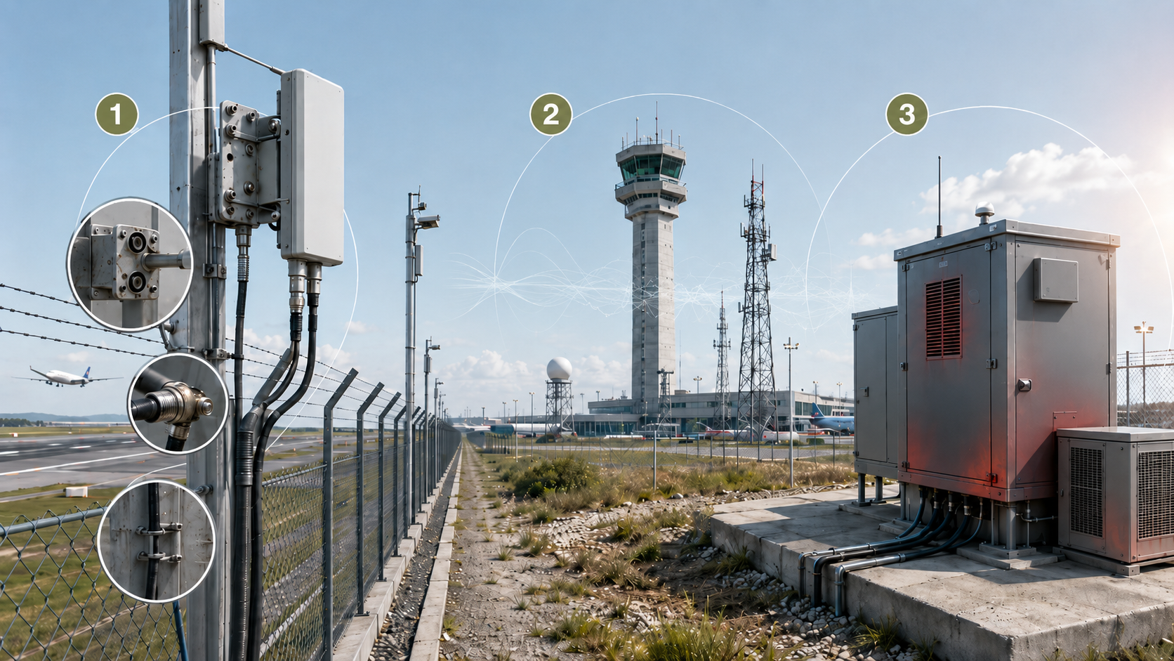
Airport RF Chain Failure Map
Airport systems fail across the RF chain when installation, spectrum control, and outdoor stability are ignored.
Mechanical Maintenance Risk
Long runway perimeters make inspection and replacement difficult. Connector durability, mounting-hole alignment, and field-access design directly affect how fast a faulty component can be replaced.
Electromagnetic Pollution Risk
Airport communication channels are highly sensitive. If the RF chain produces unwanted spurious emissions or poor spectral purity, it may interfere with air-ground communication systems and create serious compliance risk.
Outdoor Stability Risk
Airport perimeter equipment often operates inside exposed outdoor cabinets. Without proper thermal balance, power efficiency, and protection logic, component performance can shrink significantly over long-term operation.
Installation and Maintenance Constraints Across Long Runway Perimeters
Long airport boundaries turn small mechanical details into major deployment risks.
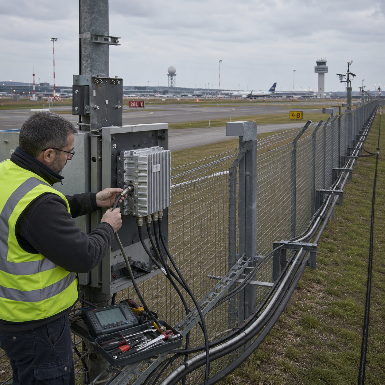
Repeated Connector Wear During Inspection
Airport inspection teams may need to disconnect and reconnect RF components for testing, replacement, or system verification. Standard low-durability interfaces can degrade after repeated physical friction, creating unstable contact quality and long-term signal risk.
Mounting Conflicts with Existing Infrastructure
Airport fences, poles, cabinets, and surveillance structures often have fixed installation conditions. If the module housing uses rigid standard mounting positions only, on-site teams may struggle to align screws, brackets, and support frames.
RF Loss Across Long Cable Runs
Airport deployment points may be far away from control cabinets or centralized equipment rooms. Long feeder cables can introduce significant RF energy loss, weakening the final signal delivered to the antenna side.
For airport sites, mechanical design is not a minor accessory. It directly determines installation speed, maintenance cost, and RF link integrity.
View Infrastructure LimitationsDelayed Deployment and Weakened RF Link Performance
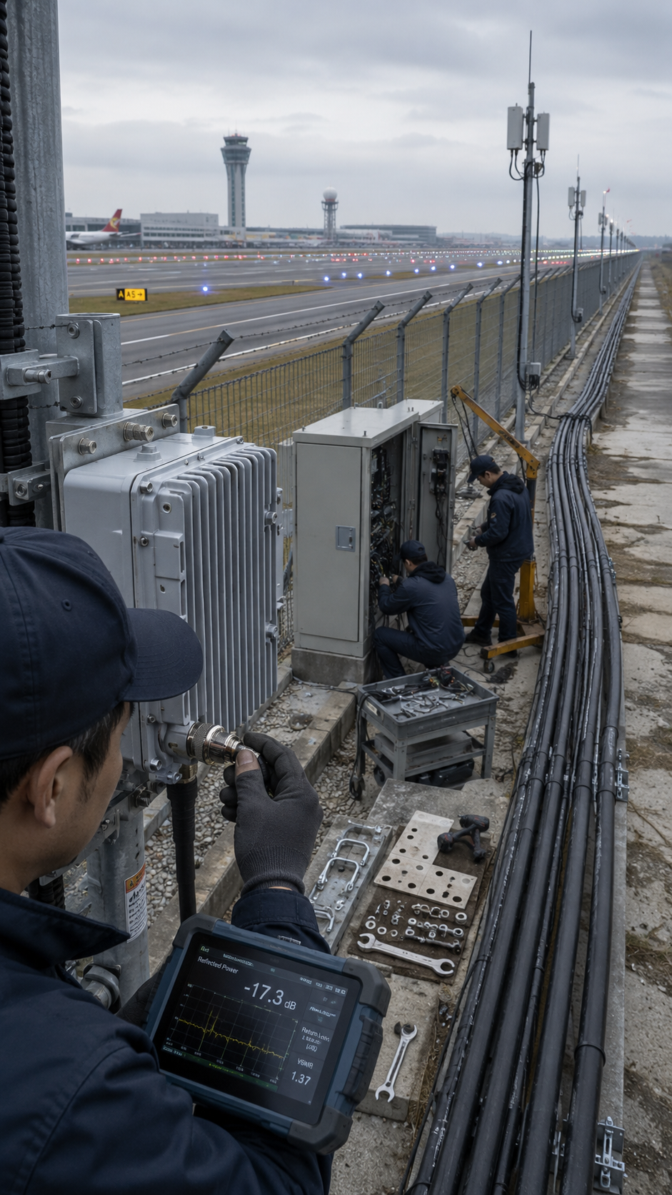
When mechanical details are ignored, the system does not only become harder to install — its RF performance also starts to degrade.
Impedance Distortion from Worn Interfaces
Excessive connector wear can cause unstable contact between RF components. This may lead to impedance mismatch, reflected power, and unstable RF behavior along the signal chain.
Rising OPEX from Difficult Replacement
If mounting holes and housing structures do not match the airport’s actual installation environment, every component replacement becomes slower. In some cases, maintenance teams may need extra manpower, lifting equipment, or bracket modification just to replace a single module.
Reduced Coverage Radius from Uncompensated Cable Loss
When long feeder loss is not calculated or compensated, high source output may fail to translate into effective terminal energy. The result is a smaller suppression radius than the system was originally designed to deliver.
In airport projects, installation delay and RF loss often come from the same root problem: components were not engineered for the field environment.
Upgrade Mechanical IntegrationField-Ready Mechanical Solution for Airport Installation and Maintenance
We design RF components around real airport deployment conditions — repeated inspection, customized mounting, and long-distance signal delivery.
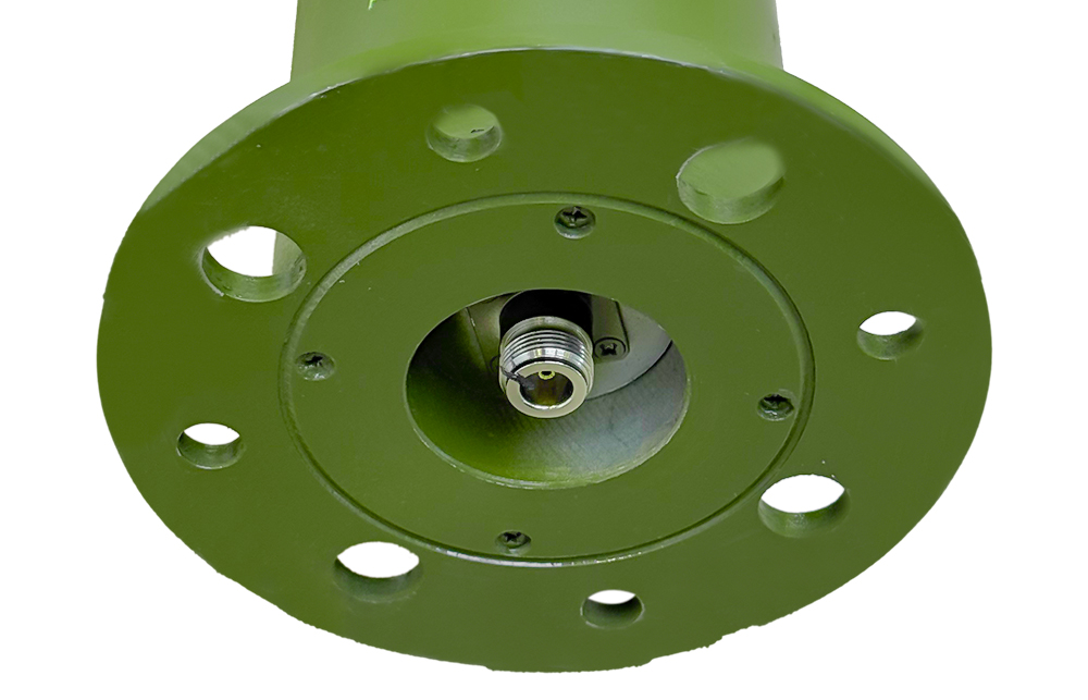
High-Durability RF Connection Design
Based on professional-grade N-type and SMA RF connector mechanical life standards, our antenna-side interface design can support repeated inspection and reconnection scenarios. For high-frequency maintenance environments, the target mating-cycle lifetime can reach 500+ cycles, helping maintain stable signal quality during long-term airport operation.
Custom Multi-Point CNC Housing
PA and SDR module housings can be customized with multi-position mounting holes according to airport brackets, fences, poles, and cabinet structures. This helps reduce on-site modification and enables faster installation across distributed runway perimeter points.
SDR-Controlled Feeder Loss Compensation
Through SDR core API control and standard AT command adjustment, the system can compensate output settings according to long feeder-loss conditions. This helps integrators maintain more predictable RF output at the terminal antenna side instead of relying only on source power.
Built for faster installation. Calibrated for predictable RF output.
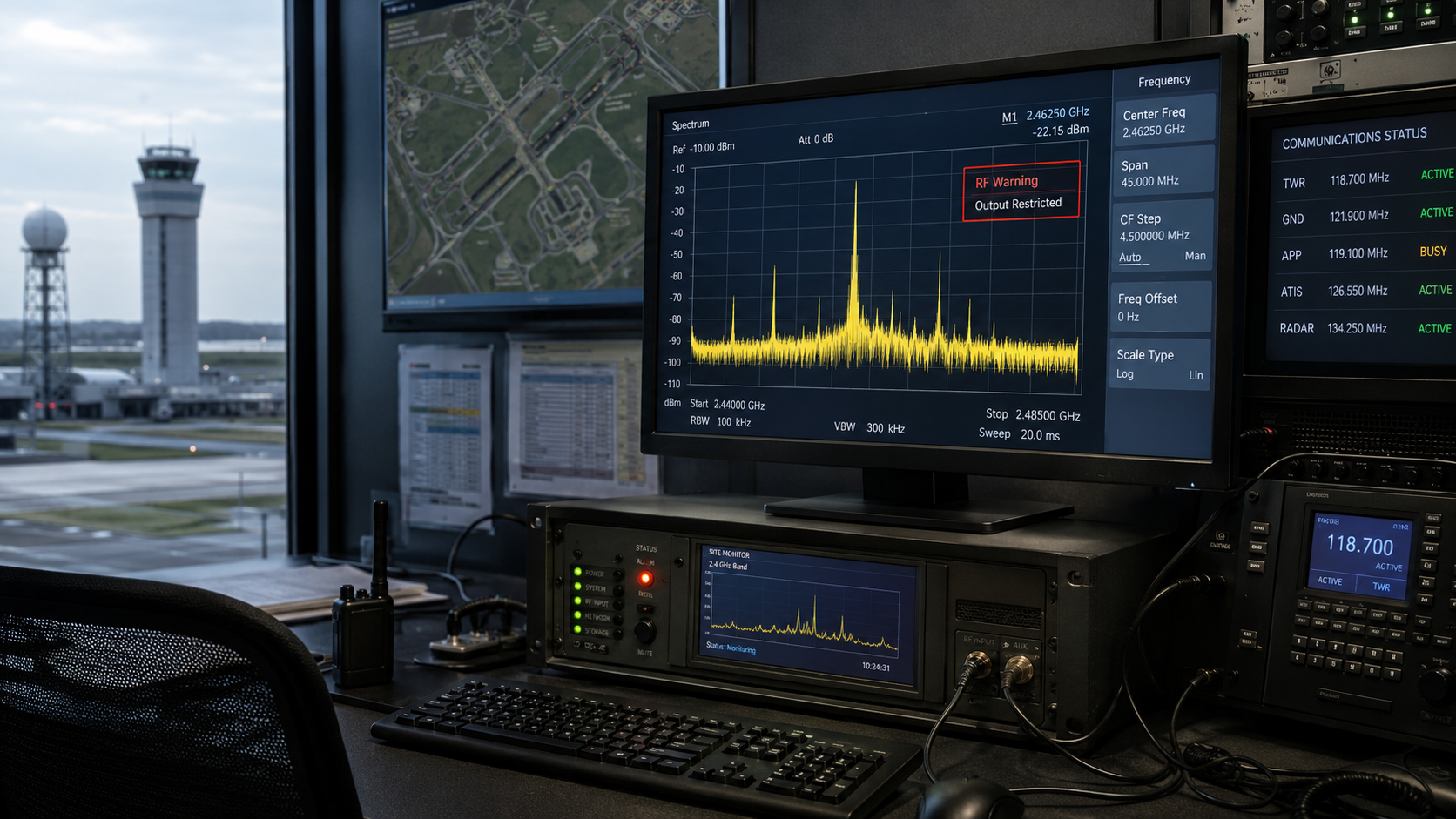
Configure Airport RF ChainSensitive Airport Spectrum Environment Requires Controllable RF Links
In airport environments, RF power without control can become a liability instead of protection.
Spectral Pollution from Impure RF Output
Low-quality interference sources may generate unwanted out-of-band emissions. In an airport environment, these spurious signals can spread into sensitive communication areas and create unacceptable operational risk.
Cross-Distortion During Multi-Band Operation
When multiple frequency bands are activated at the same time, poor RF chain design can create intermodulation and distortion. This reduces signal quality and makes the system harder to control.
False Confidence from Inefficient Power
High displayed power does not always mean effective suppression. If power conversion is inefficient or signal quality is poor, the system may appear strong on paper while delivering unstable or polluted RF output in the field.
Airport RF defense requires clean, disciplined, and controllable output — not uncontrolled wideband force.
View Compliance RisksUncontrolled RF Output Can Force System Shutdown
Aviation Complaints and Legal Liability
If RF purity is not controlled, unwanted emissions may interfere with airport communication systems. Once interference is reported, the deployed system may be restricted, suspended, or permanently removed from operation.
Diminishing Suppression Efficiency
Severe distortion spreads useful RF energy into unwanted areas. As a result, even high-power output may fail to form an effective suppression envelope against drone control links.
Internal Self-Stress and Frequency Drift
When RF conversion efficiency is poorly managed, excess heat builds up inside the signal source and GaN amplifier. This thermal stress can increase frequency drift, noise, and distortion during critical airport operation.
In airport security, RF instability is not just a product defect. It can become a compliance problem, an operational shutdown risk, and a direct threat to mission continuity.
Configure Clean RF ArchitectureClean RF Chain with Airport-Band Avoidance Logic
We provide controllable, configurable, and verifiable RF chain capabilities for airport integrators — not brute-force wideband noise.
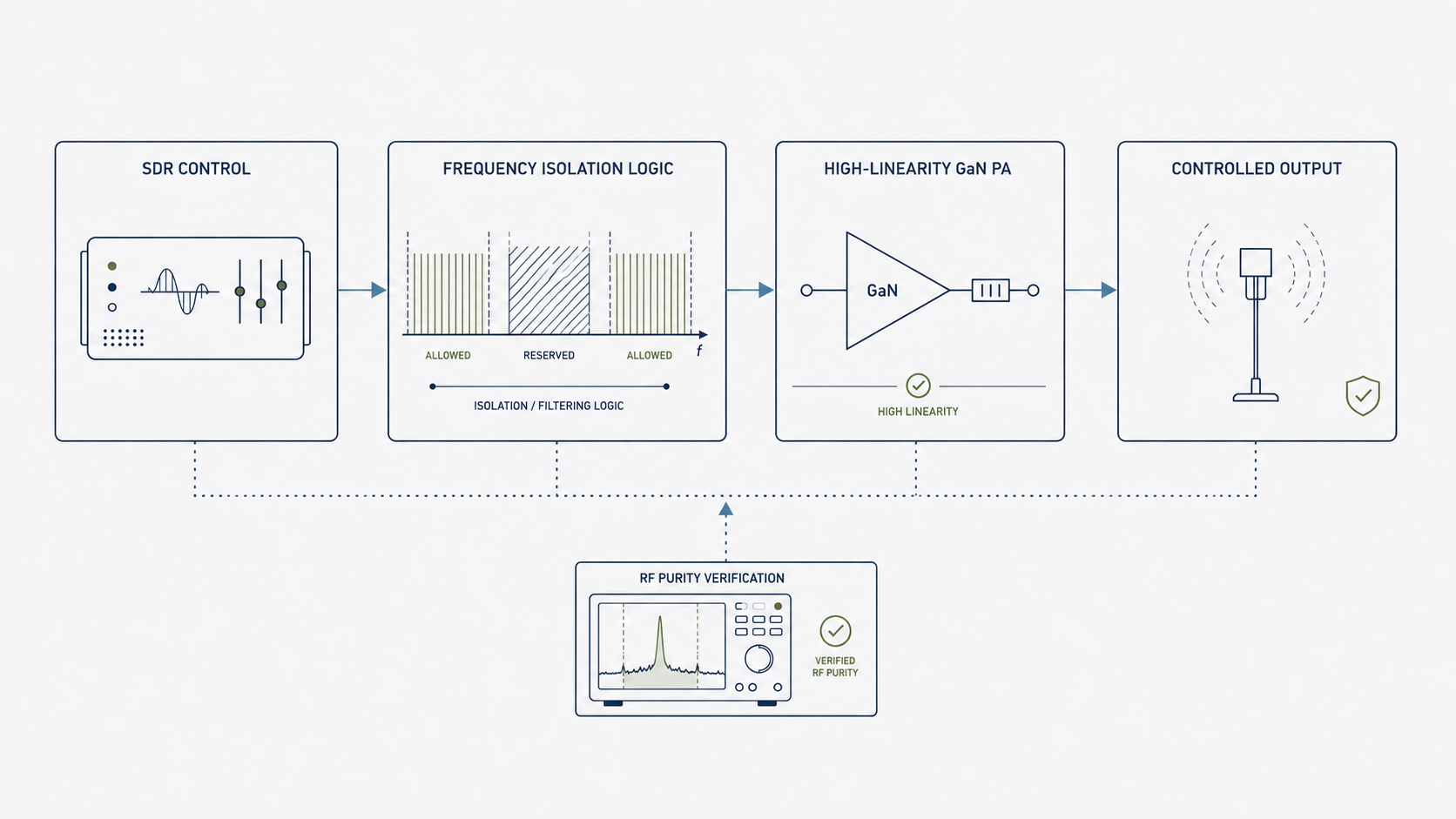
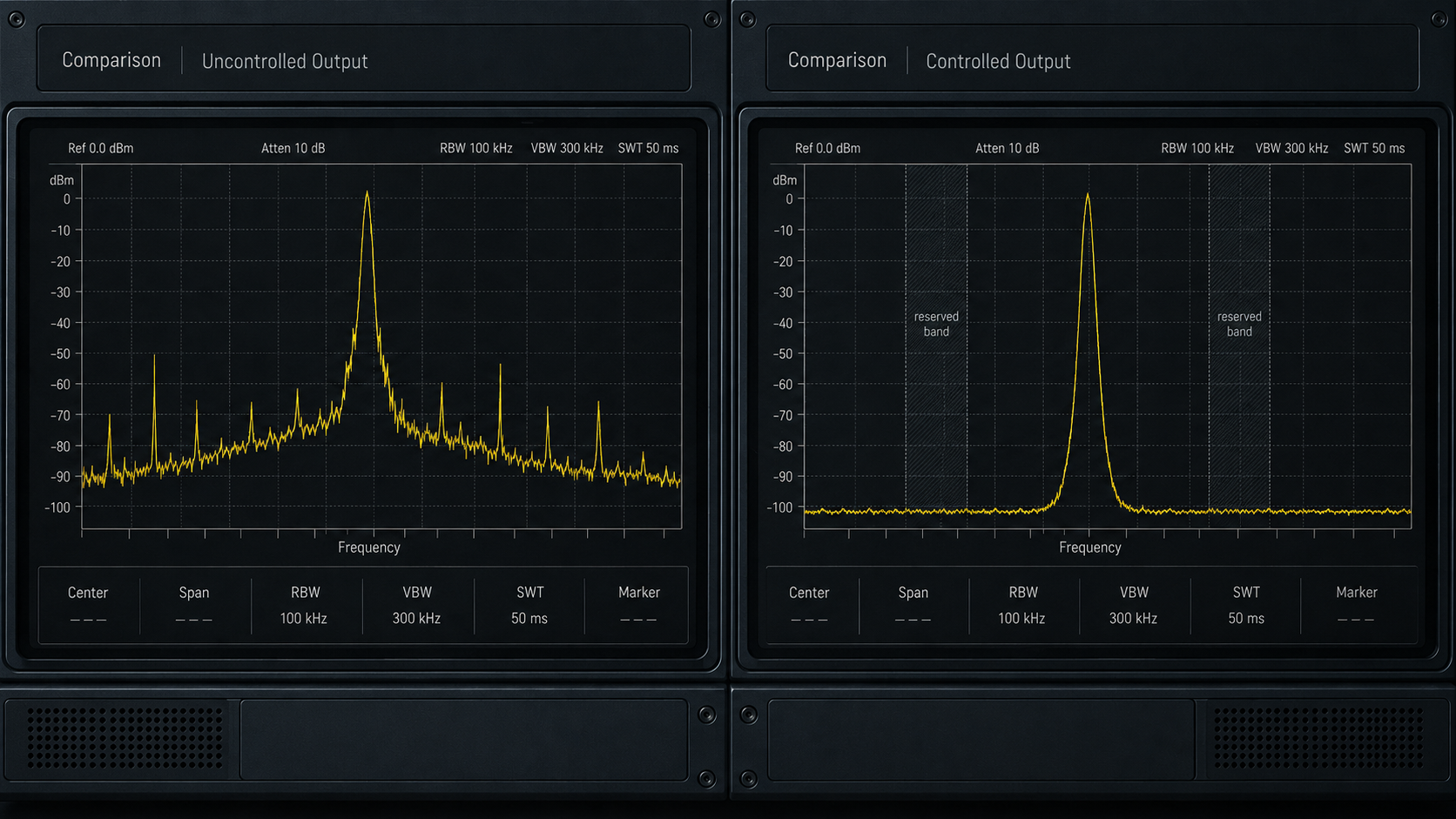
Protocol-Level Frequency Isolation Logic
Using SDR software-defined control, protected airport communication and navigation channels can be reserved during system configuration. Instead of uncontrolled sweeping, the system enables more precise frequency targeting and “surgical” suppression behavior.
High-Efficiency, High-Linearity GaN Amplification
Third-generation GaN power amplifier technology improves power conversion efficiency and supports cleaner RF output with lower distortion. This helps reduce waste heat, improve signal quality, and maintain more stable suppression performance in sensitive airport environments.
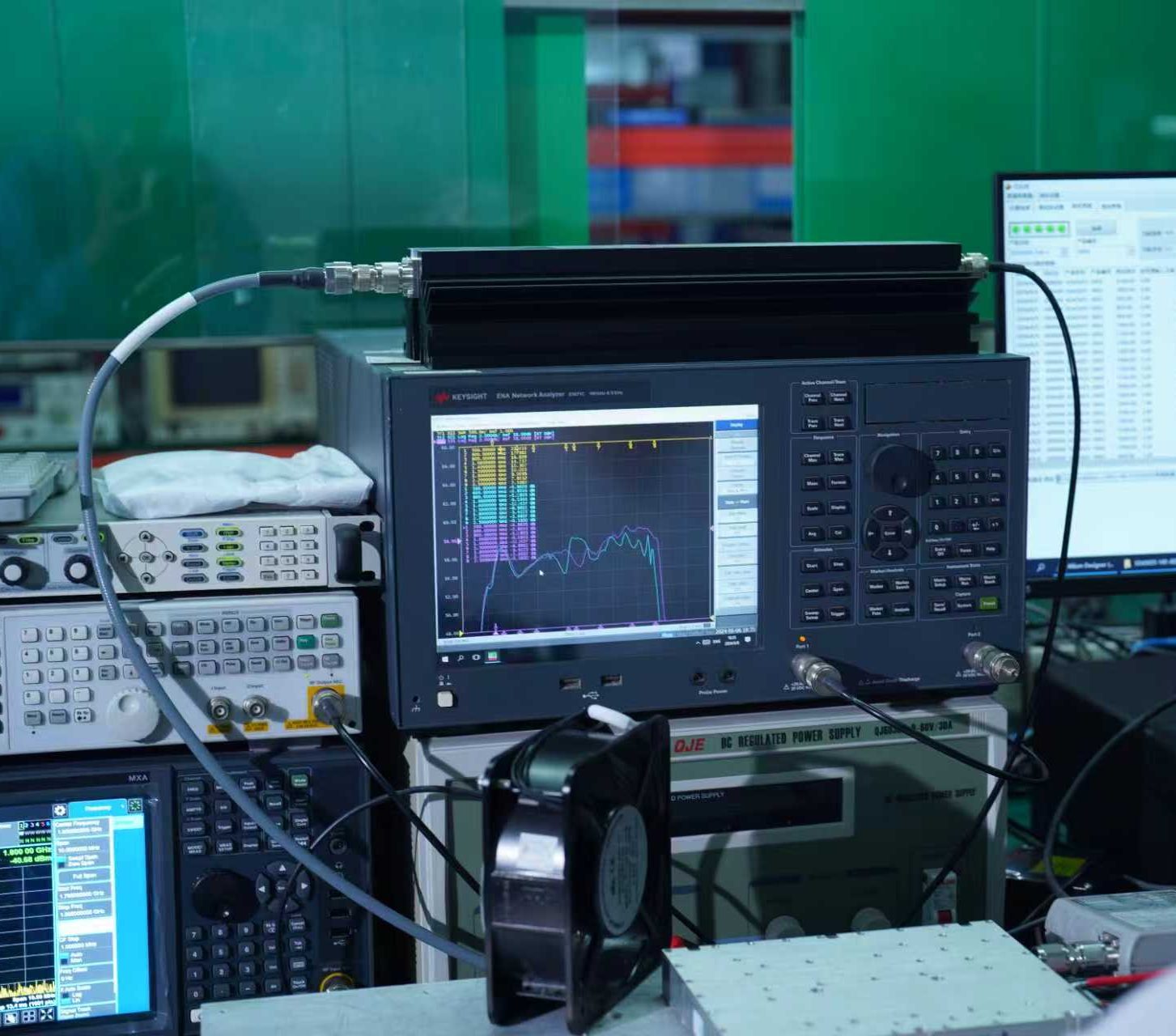
Measurable RF Purity Before Deployment
For airport projects, signal quality must be verified, not assumed. By testing distortion, efficiency, and spectral cleanliness, integrators can confirm that the RF chain meets the site’s operational requirements before final deployment.
The goal is not maximum noise. The goal is controlled energy — delivered only where the airport defense mission requires it.
Explore Thermal Management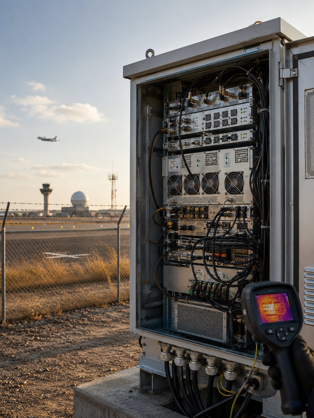
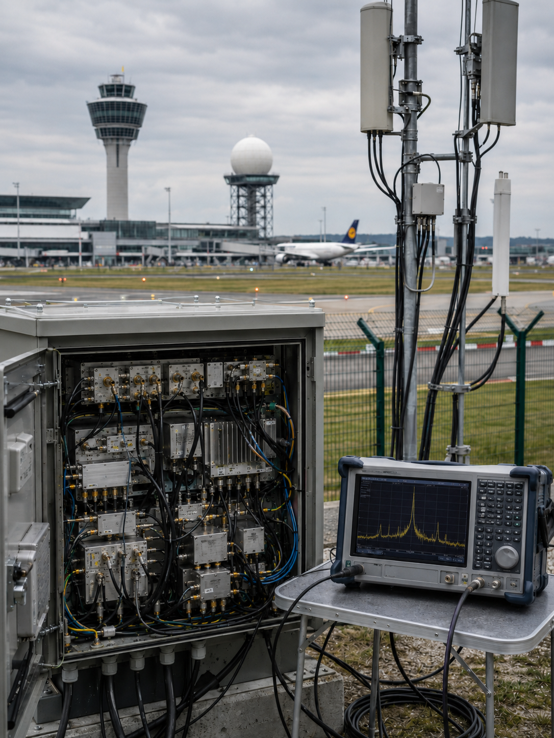
Long-Term Outdoor Airport Cabinets Struggle to Maintain Thermal Balance
Airport perimeter equipment must survive continuous operation in sealed, exposed, and electrically unstable environments.
Heat Accumulation in Sealed Cabinets
Airport perimeter devices are often installed inside passive or semi-enclosed outdoor cabinets. Without effective thermal design, internal heat builds up and becomes difficult to release.
Physical Fatigue Under Continuous Load
A 24/7 operating profile places constant stress on RF modules, amplifier components, connectors, and internal protection circuits. Long-term duty requires more than short-term lab performance.
Temporary Power Voltage Fluctuation
Remote airport perimeter infrastructure may experience unstable power input. Voltage fluctuation can place additional stress on PA modules and control systems, especially during long-duration operation.
For airport outdoor deployment, stability must be designed for continuous load, not temporary demonstration.
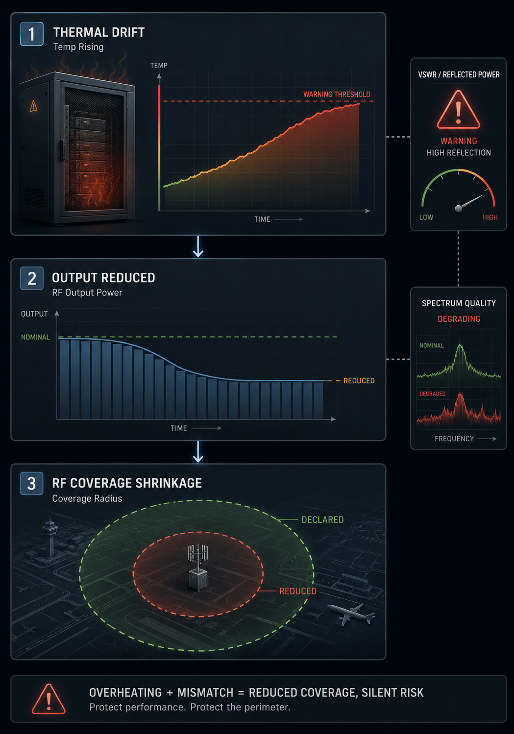
View Hardware Damage RisksThermal Drift, Power Reduction, and Hardware Damage Risks
When heat, reflection, and distortion are not controlled, the defense radius can shrink without warning.
Power Limiting from Thermal Imbalance
When internal temperature rises too quickly, the amplifier may reduce output power to protect itself. This protects the hardware temporarily, but also reduces the effective defense coverage.
Instant Damage After VSWR Abnormality
If an antenna is damaged, disconnected, or poorly matched, reflected energy can return toward the amplifier. Without intelligent VSWR protection, this reflected power may damage the PA core.
Distortion Worsening at High Temperature
As temperature rises, RF performance can become less stable. Signal distortion may increase, spectral purity may degrade, and the system may become less reliable during long-term airport operation.
A 24/7 airport system must protect both the airspace and itself. Thermal control, VSWR protection, and distortion stability are part of the same reliability chain.
Deploy 24/7 Defense SystemBuilt for 24/7 RF Stability
Built for outdoor RF operation under heat, reflection, and voltage stress.
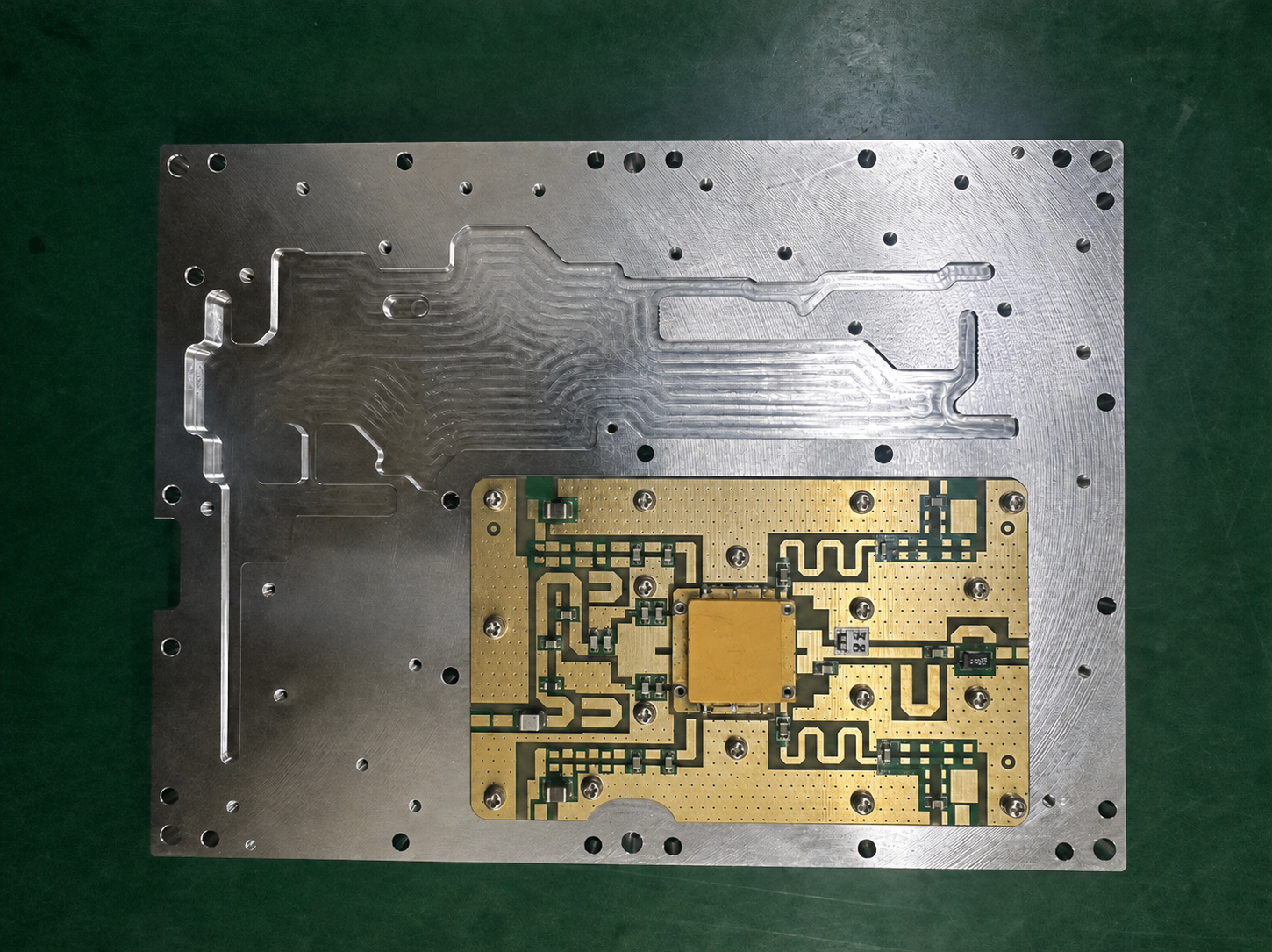
CNC Thermal Structure
The module housing is built around CNC-machined aviation aluminum to improve thermal conduction and structural stability. By treating the housing as part of the thermal system, the module can better maintain heat balance during continuous operation. This helps support honest 100% duty-cycle output instead of short-term peak performance that collapses under outdoor cabinet heat.
VSWR & Thermal Protection
The PA module integrates over-temperature shutdown and VSWR detection logic to reduce the risk of hardware damage caused by antenna mismatch, reflected power, or extreme cabinet conditions. When internal temperature reaches the protection threshold, the system can trigger automatic shutdown behavior. VSWR monitoring helps prevent reflected energy from burning the amplifier core during antenna damage, disconnection, or mismatch events.
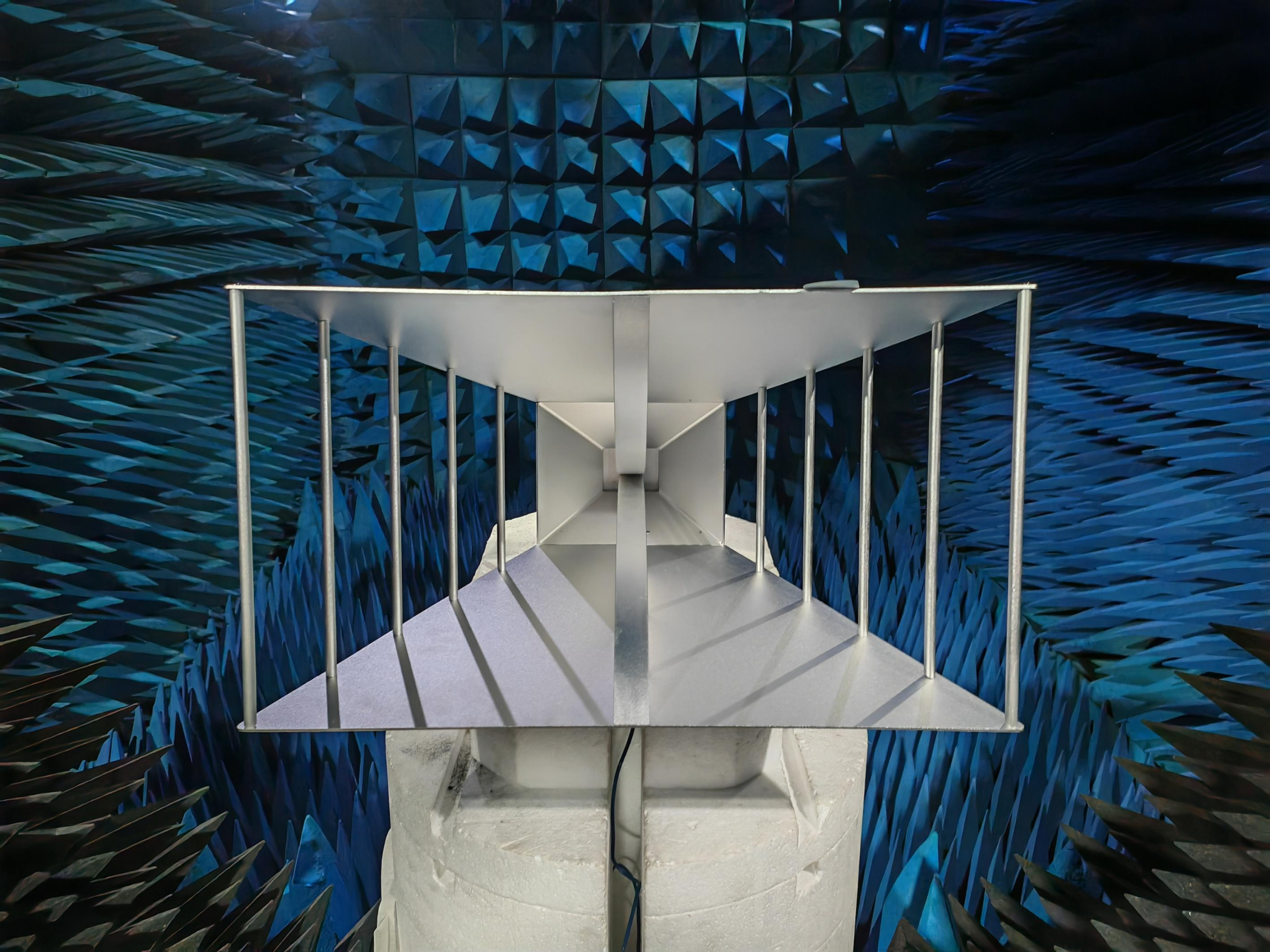
Low-Distortion Wideband Antenna
Airport outdoor systems may face extreme temperature changes across seasons and regions. Wideband antenna components with high-linearity and low-distortion design help maintain RF stability under harsh environmental conditions. Designed for performance stability across -40°C to +70°C operating challenges, the antenna side supports long-term airport perimeter deployment where signal quality must remain predictable.
Thermal structure, protection logic, and antenna stability work as one reliability chain.
Explore Asset Standardization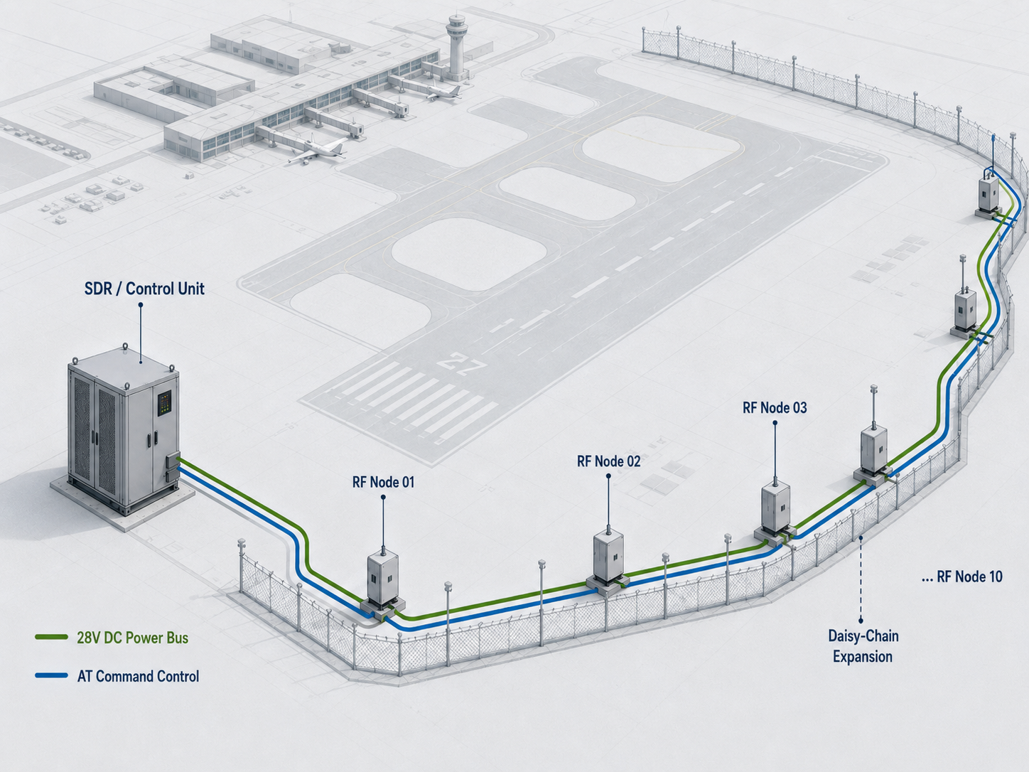
Standardized Architecture for Long-Term Airport Maintenance Risk Reduction
Turn complex airport perimeter wiring into a long-term upgradeable RF asset.
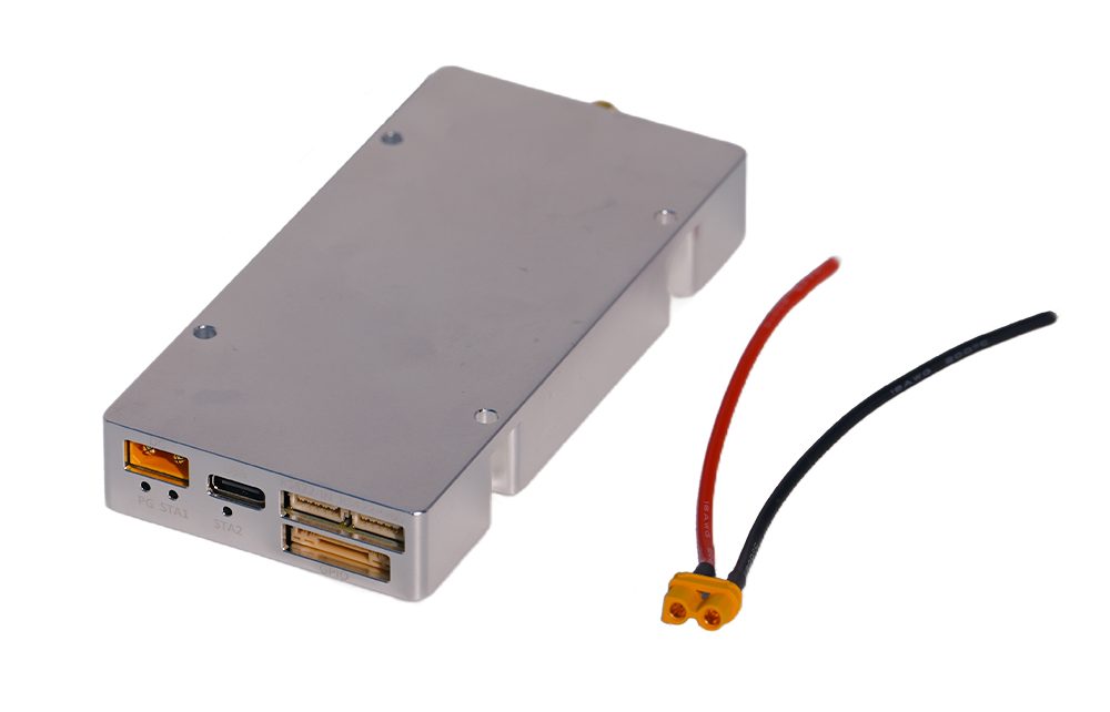
Unified 28V Industrial Power Alignment
A consistent 28V power architecture helps simplify power planning across distributed airport perimeter devices and reduces integration complexity.
Standard AT Command Control Set
Standard AT command logic allows integrators to control compatible RF components through a more predictable command structure, reducing proprietary interface barriers.
Up to 10-Device Daisy-Chaining
The system architecture supports up to 10-device daisy-chain deployment, helping integrators expand distributed RF nodes without redesigning the entire wiring structure.
Structural Consistency from Engineering Drawings to Batch Housings
Airport projects cannot afford a sample that fits perfectly while the production batch fails on site.
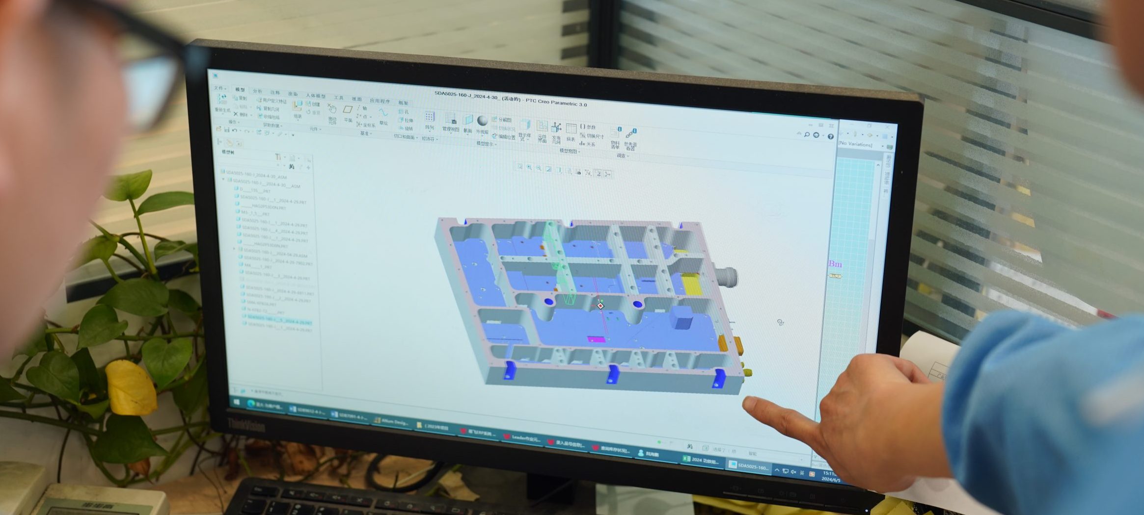
Controlled from Drawing Stage
Mounting positions, housing structure, connector layout, and thermal design are considered from the engineering drawing stage, not adjusted randomly after production begins.
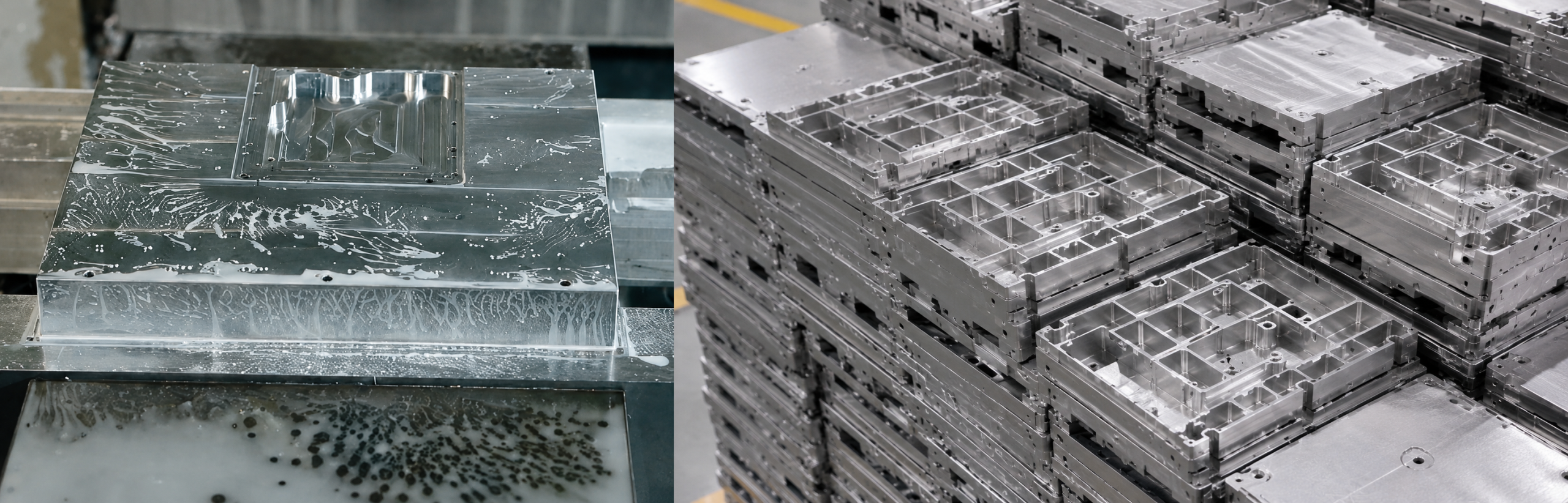
In-House CNC Machining
Our own CNC machining capability helps keep critical structural details under factory control instead of depending on outsourced trial-and-error processing.
Batch-to-Batch Structural Baseline
Each production batch follows the same structural reference, helping airport integrators maintain consistency during multi-point deployment, replacement, and long-term maintenance.
Digital Birth Certificate: Accountability for Every Meter of Protected Airspace
Every custom component should carry measurable proof before entering airport security infrastructure.
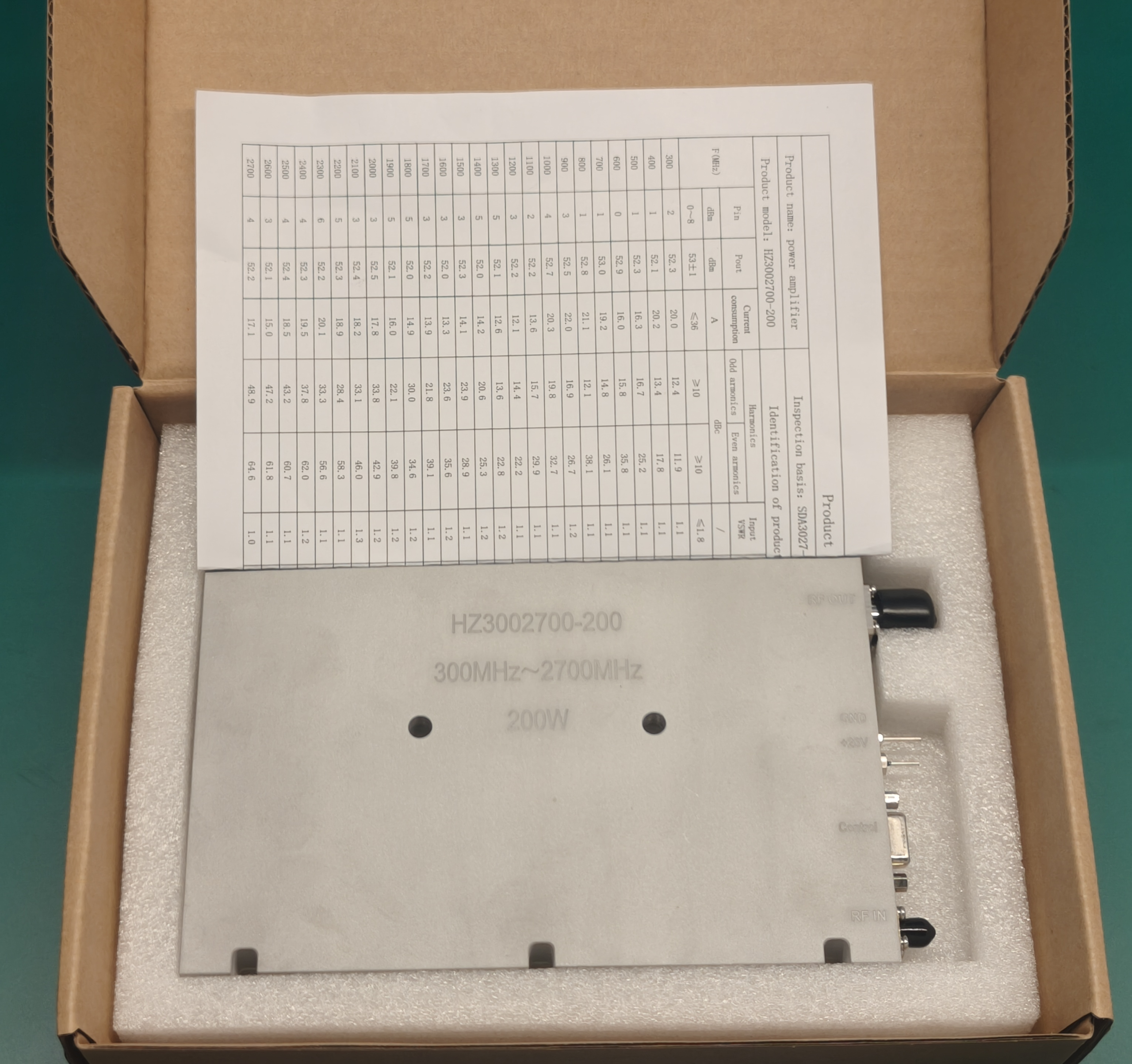
One Report for Every Custom Component
Each custom SDR, PA, or RF component can be delivered with an independent digital performance report tied to its measured behavior.
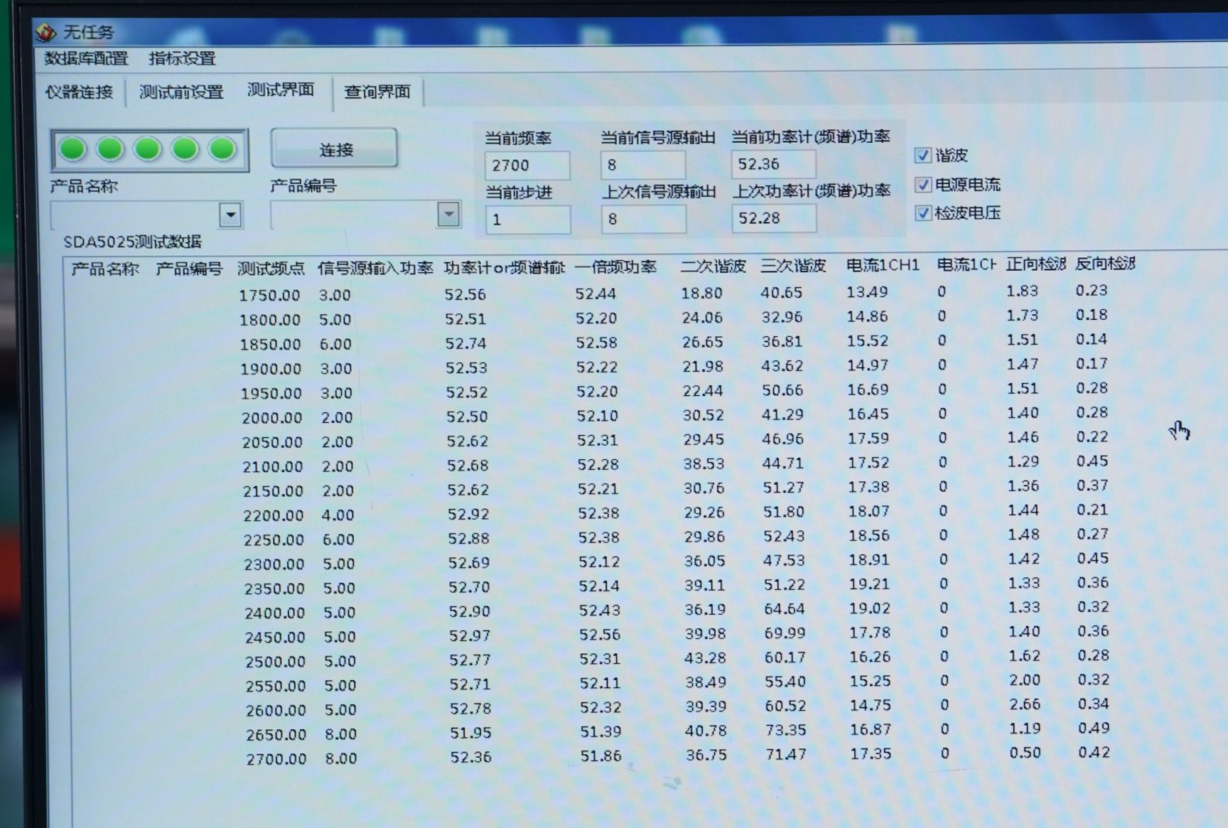
Measured Distortion, Efficiency, and Spectral Purity
Instead of relying only on claimed specifications, the report records real-world RF performance data relevant to airport deployment.
Compliance Support for Integrators
The report helps integrators communicate with airport management teams and reduce the risk of disputes related to illegal interference or uncontrolled RF output.
Start Your Industry-Grade Airspace Customization
Skip the sales talk. Align directly with our RF engineers.
Every operational perimeter is different. Coverage length, local communication channels, cabinet environment, cable distance, and maintenance workflow all affect how the RF chain should be designed.
Share your project conditions with our engineering team. We evaluate frequency planning, power matching, and long-term outdoor stability before system integration begins.