


RF Power Amplifier input power makes tests fail when the actual drive level is not defined, measured, or matched to the amplifier’s recommended operating window. For a C-UAS integrator, the problem is rarely just “Can this module make 100 W?” The better question is “At what RF input power, measured where, under which frequency, duty cycle, load, and thermal condition?” If the input drive level is too low, a healthy amplifier may look weak. If it is too high, the module may enter compression, distort the spectrum, trigger protection, or run hotter than the review data suggests. This article gives you a practical framework for judging RF Power Amplifier input power before sample testing, RFQ comparison, and production approval.
1. What Does RF Power Amplifier Input Power Mean?
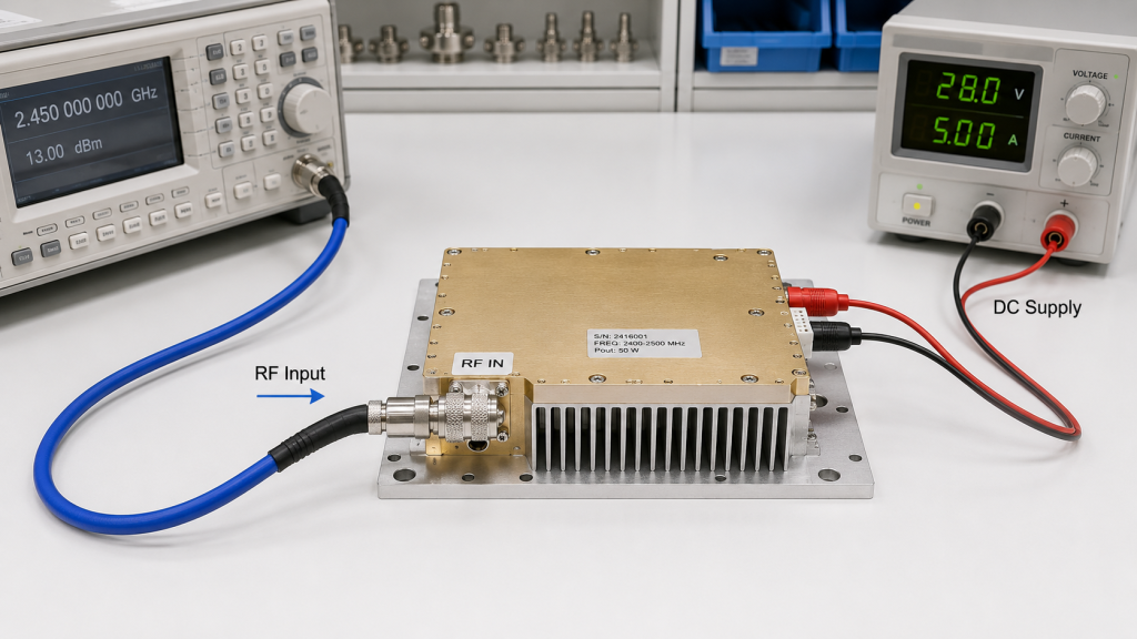
RF input power means the RF drive level delivered to the amplifier input port, not the DC supply power feeding the module. In RF Power Amplifier input power evaluation, this distinction matters because the RF input signal controls what the amplifier can amplify, while DC voltage and current provide the energy behind that amplification.
Here’s the engineering point: the value that matters is the calibrated power at the PA input connector, not only the signal generator display. A typical chain may include an SDR, driver amplifier, cable, switch, attenuator, and connector transitions before the PA sees the signal. If DC-side behavior also needs review, compare this RF input-drive check with the separate DC power supply stability requirements before judging the module.
How Should You Define the Input Reference Point?
You should define the input reference point at the module RF input connector whenever possible. If the test report only states the signal source setting, you still do not know what reached the amplifier after path loss and intermediate components.
- Signal source output is not always module input.
- Cable loss can reduce the actual drive level.
- Fixed attenuators can hide several dB of loss.
- Driver amplifiers can push the PA into compression.
- Connector changes can alter repeatability.
Key Takeaway: RF input drive must be defined at the amplifier input port so output data can be compared fairly.
| Parameter | What It Means | Why It Matters |
|---|---|---|
| RF input power | Drive signal into RF port | Sets output behavior |
| DC supply power | Voltage and current supply | Supports energy conversion |
| Calibration plane | Where power is measured | Controls test accuracy |
| Input connector power | Actual PA drive level | Best basis for judgment |
If the input reference point is vague, every output number becomes harder to trust.
2. How to Judge RF Power Amplifier Input Power Test Data?
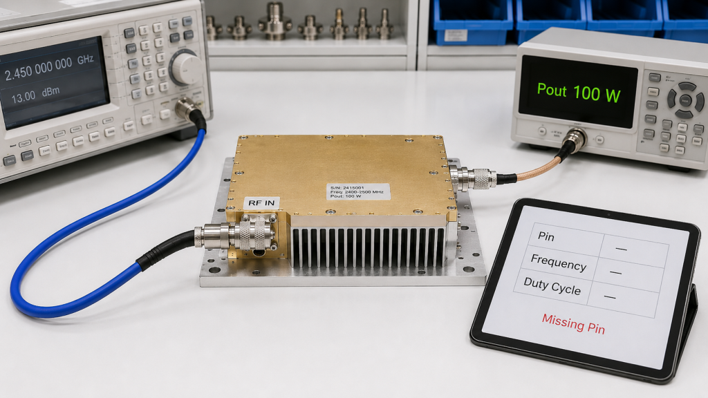
Output data is misleading without input drive because the same watt reading can come from very different operating conditions. In RF Power Amplifier input power reviews, a 100 W screenshot alone does not tell you gain, compression margin, source compatibility, or safe operating headroom.
The practical risk is clear: one module may reach rated output with +0 dBm input, while another may need +10 dBm. Before comparing suppliers or samples, you should ask for Pin, Pout, frequency, gain, load, DC supply, duty cycle, and test duration together.
What Should a Useful Test Report Include?
A useful test report should connect output power to repeatable input conditions. Without those conditions, the report may still be a real measurement, but it is not strong enough for serious sourcing or factory acceptance review.
- Input drive at the PA connector
- Output power at defined frequency points
- Gain calculation from Pin and Pout
- Load condition and VSWR state
- DC voltage and current during the test
- Thermal state before and after operation
You can compare this with a broader full-band RF verification process when the module must work across multiple C-UAS bands.
Key Takeaway: Output power without input drive conditions is a result without a usable test method.
| Missing Detail | Likely Problem | Review Impact |
|---|---|---|
| Pin not listed | Gain cannot be verified | Weak selection basis |
| Frequency absent | Band edge risk hidden | Poor full-band judgment |
| Load unclear | Reflected power ignored | Reliability risk |
| Duration absent | Peak data overvalued | CW risk underestimated |
Good procurement data should let another engineer reproduce the result.
3. What If RF Power Amplifier Input Power Is Too Low?
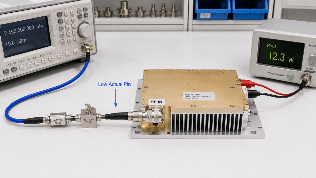
When RF input power is too low, the amplifier may operate normally but fail to reach the expected output level. In RF Power Amplifier input power testing, underdrive can make a good module look defective because it is never given enough signal to amplify.
This is where system integrators should pay attention: SDR outputs, source modules, long RF cables, switch matrices, and attenuators can all reduce drive before the PA input. If you are evaluating SDR signal source module compatibility, confirm the real drive range after the full source path, not only the source specification.
How Does Underdrive Distort Judgment?
Underdrive mainly creates false negative conclusions during testing and acceptance. The module may still be healthy, but the RF chain has not supplied the drive level needed to reach the rated output.
- Rated output may not be reached.
- Gain may appear lower than expected.
- Coverage estimates may look worse than reality.
- Procurement may reject a suitable PA.
- Engineers may increase wattage unnecessarily.
Key Takeaway: Underdrive can turn a source-chain problem into a false PA failure.
| Underdrive Cause | Test Symptom | Better Check |
|---|---|---|
| SDR output too low | Low Pout | Measure Pin at PA input |
| Cable loss | Missing dB | Calibrate cable path |
| Excess attenuation | Weak output | Verify attenuator value |
| Switch path loss | Band-dependent drop | Test each route |
Before blaming the amplifier, confirm that the module received the intended drive.
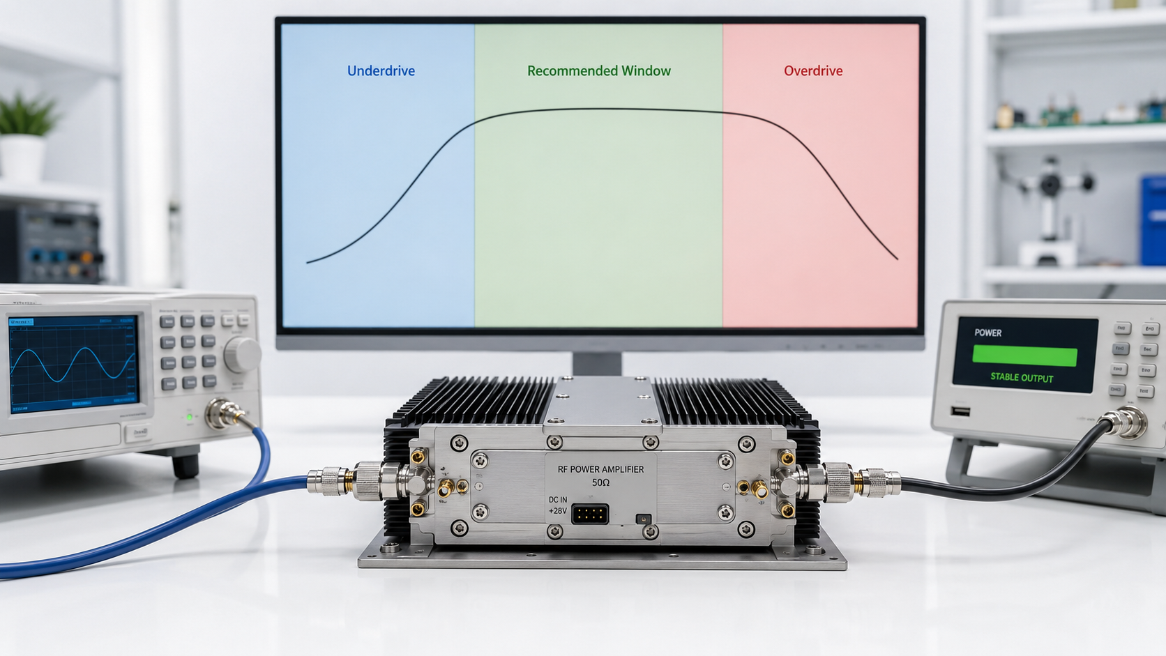
4. What If RF Power Amplifier Input Power Is Too High?
When RF input power is too high, the amplifier may move into compression, distortion, thermal stress, protection, or damage risk. In RF Power Amplifier input power selection, overdrive is often more dangerous than underdrive because it can produce an attractive watt number while hiding poor operating quality.
Here’s the field reality: increasing drive does not create unlimited clean output. Once the amplifier leaves its recommended input window, gain no longer rises proportionally, current may increase, temperature can climb, and alarms may appear depending on the module design.
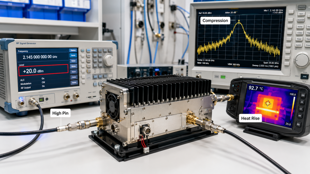
How Does Overdrive Change the Output?
Overdrive changes both the power result and the quality of that result. A higher watt number may come with worse spectral behavior, lower repeatability, and higher stress on the RF power stage.
- Gain compression reduces predictable amplification.
- Harmonics and spurious output may increase.
- Current draw may rise sharply.
- Heat load becomes harder to control.
- Protection may fold back or shut down output.
Key Takeaway: A higher output number from overdrive should not be treated as a reliable operating point.
| Overdrive Effect | What You May See | Why It Matters |
|---|---|---|
| Compression | Pout stops rising cleanly | Gain data becomes misleading |
| Distortion | Poor spectrum behavior | System quality risk |
| Heat rise | Temperature climbs faster | Reliability risk |
| Protection | Alarm or shutdown | Acceptance instability |
The right input drive is the range that produces stable output, not the highest possible watt reading.
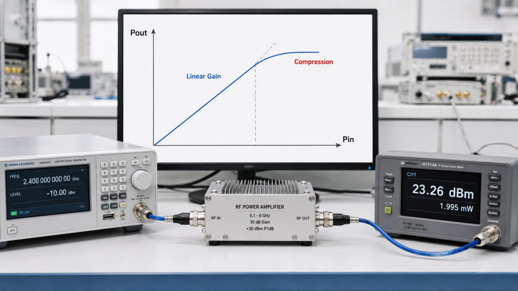
5. How Does Input Drive Affect Gain and Compression?
Input drive affects gain and compression because amplifier behavior changes between small-signal testing, rated output, and overdrive. In RF Power Amplifier input power analysis, gain should always be read together with Pin, Pout, frequency, and whether the module is near compression.
Here’s the engineering point: a smooth small-signal gain curve does not prove full-power behavior. A module may show excellent gain at low input, then compress at rated output, especially near band edges or under high duty cycle operation.
Which Gain Condition Should You Compare?
You should compare gain under the operating condition closest to your system. For wideband projects, gain behavior should also be compared with gain flatness test data so you do not mix small-signal curves with rated-output behavior.
- Small-signal gain helps show baseline behavior.
- Rated-drive gain shows practical output behavior.
- P1dB behavior shows compression margin.
- Overdrive gain should not define normal use.
- Full-band gain reveals frequency-related variation.
Key Takeaway: Gain is meaningful only when the input drive condition is stated.
| Gain View | Input Condition | Best Use |
|---|---|---|
| Small-signal gain | Low drive | Baseline comparison |
| Rated gain | Recommended drive | System selection |
| Compressed gain | Near saturation | Margin review |
| Overdrive result | Above safe range | Risk identification |
Do not mix small-signal gain, rated output gain, and overdrive data as if they describe the same state.
6. How to Check RF Power Amplifier Input Power Across Band?
You should check RF input power across the full band because a fixed drive level may not produce the same output at low, middle, and high frequency points. In RF Power Amplifier input power testing, wideband modules can need different input drive levels because gain, matching, and efficiency vary with frequency.
The practical risk is clear: a module may look excellent at the center frequency but fall short at the upper or lower edge. This is why input-drive review should sit beside RF Power Amplifier frequency range selection instead of being checked after the band is already approved.
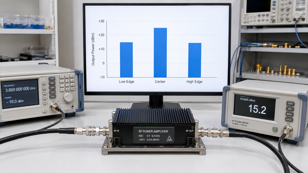
What Full-Band Data Should You Request?
Full-band data should show how Pin and Pout move together across the usable operating range. For broad ranges such as 300-1200 MHz, 300-2700 MHz, or 2000-6000 MHz, center-point input data should never represent the whole module.
- Low, middle, and high frequency points
- Pin/Pout curve across the band
- Gain flatness trend
- Output drop near band edges
- Compression signs at rated drive
- Temperature trend during longer testing
You can use the RF power amplifier module range as a starting point, then request project-specific Pin/Pout data for your exact band.
Key Takeaway: Full-band Pin/Pout data helps you avoid choosing a module based on one favorable frequency point.
| Band Position | Possible Behavior | Review Action |
|---|---|---|
| Low edge | Matching may shift | Verify output and gain |
| Center | Often strongest data | Do not overgeneralize |
| High edge | Gain may fall | Check drive requirement |
| Full sweep | Trend becomes visible | Judge real usability |
A wideband label is useful only when the input drive window is verified across the band.
7. How Do Cables and Adapters Change Real Input Power?
Cables and adapters change real input power by adding loss, mismatch, contact variation, and frequency-dependent uncertainty before the signal reaches the amplifier. In RF Power Amplifier input power measurement, these path losses can make the PA input several dB different from the source setting.
This is where test discipline matters: if the signal generator says +5 dBm, the PA may not receive +5 dBm after cables, attenuators, adapters, switches, and connector transitions. For repeatable testing, use clear adapter-loss control methods and document the calibration plane.
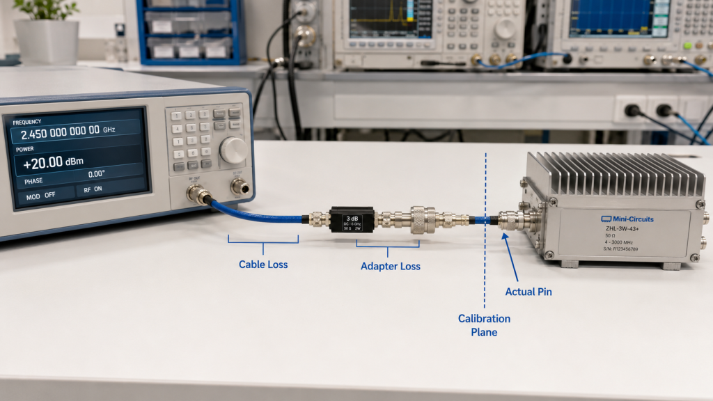
What Should Be Calibrated Before Testing?
You should calibrate the input path before interpreting output power. The goal is not to make the test setup complicated; the goal is to remove hidden variables before blaming or approving the amplifier.
- Cable loss at each test frequency
- Attenuator value and tolerance
- Switch or matrix insertion loss
- Adapter stack and connector condition
- Power meter reference point
- Torque and repeatability for connectors
Key Takeaway: The real input drive is the calibrated power at the PA connector, not the front-panel setting.
| Path Element | Typical Issue | Data Risk |
|---|---|---|
| RF cable | Frequency-related loss | Underdrive |
| Attenuator | Wrong value or tolerance | False Pin |
| Adapter | Contact variation | Poor repeatability |
| Switch matrix | Route-dependent loss | Inconsistent output |
A clean input path is often the fastest way to make PA data more credible.
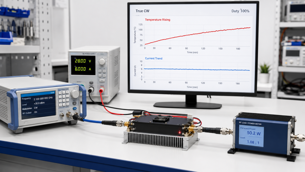
8. How Do Duty Cycle and RF Input Drive Interact?
Duty cycle and RF input drive interact because compression, current rise, and heat have more time to accumulate during longer operation. In RF Power Amplifier input power reviews, a drive level that looks acceptable in a short pulse test may be risky under high-duty or True CW conditions.
Here’s the field reality: overdrive during a brief bench check may only show a higher output number, but under continuous operation it can trigger thermal foldback or shutdown. Underdrive also matters because a system may pass a short functional test but fail coverage expectations during long deployment.
What Should Duty-Cycle Testing Record?
Duty-cycle testing should record drive, output, heat, and protection behavior together. If the system is expected to run near continuous output, you should also review RF Power Amplifier reliability factors before treating a short test as approval evidence.
- Input drive level at the PA connector
- CW, pulsed, or intermittent waveform state
- Test duration and duty cycle
- Temperature curve over time
- Current draw trend
- Alarm or foldback events
Key Takeaway: Input power cannot be judged separately from duty cycle when reliability is part of the approval.
| Operating Mode | Input Risk | Review Focus |
|---|---|---|
| Short pulse | Peak data overvalued | Check repeatability |
| Intermittent | Heat cycles vary | Watch recovery behavior |
| High duty cycle | Compression heat grows | Track temperature |
| True CW | Long stress exposure | Confirm stable drive window |
The closer your system is to continuous operation, the more conservative your input-drive review should be.
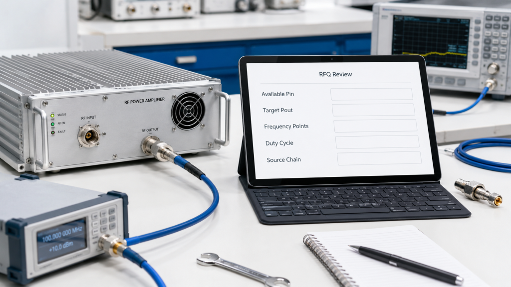
9. What RF Input Details Belong in an RFQ?
An RFQ should define both the target output power and the RF input drive available to reach it. In RF Power Amplifier input power procurement, a watt target alone is incomplete because the supplier cannot judge whether your source chain can drive the selected PA correctly.
Here’s the practical point: if you do not know the real input level yet, describe the source model, driver chain, cable length, attenuators, waveform, and acceptance method. For buyers preparing a project file, the RFQ submission page is the right place to attach frequency range, target power, source-chain notes, and available drive level.
What Should You Ask the Supplier to Confirm?
You should ask for the input conditions that make the output repeatable. This helps both sides avoid a common mistake: approving a module on paper before confirming whether the source chain can drive it correctly.
- Recommended input drive level
- Maximum safe input power
- Pin/Pout curve at key frequencies
- Gain at rated output
- Compression behavior
- Required source or driver capability
- Test setup and calibration point
Key Takeaway: A good RFQ prevents input-drive mismatch before sample testing begins.
| RFQ Item | Why Include It | Result |
|---|---|---|
| Available Pin | Confirms drive match | Fewer sample surprises |
| Target Pout | Defines output need | Clear rating comparison |
| Frequency points | Shows band demand | Better full-band review |
| Duty cycle | Defines stress level | Better reliability check |
The best RFQ makes the expected operating condition visible before anyone quotes a module.
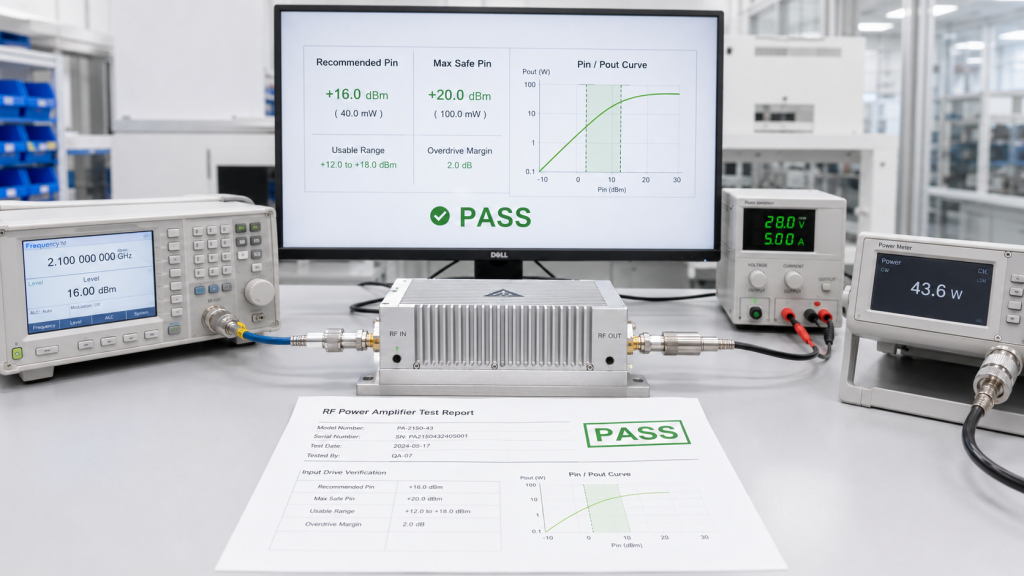
10. How to Verify RF Power Amplifier Input Power Window?
Factory testing confirms the drive window by measuring repeatable Pin/Pout behavior across frequency, output level, duty cycle, thermal state, and protection limits. In RF Power Amplifier input power approval, source-factory testing should prove the recommended input range instead of only showing one maximum output number.
This is where RF SKYPOWER’s engineering role fits naturally: RF module design, CNC housings, copper heat spreaders, VSWR, temperature, voltage protection, and repeatable test reports all support better integration decisions. For startup and fault handling, a documented safe PA control sequence also helps you avoid applying RF input when the rest of the system is not ready.
What Should the Factory Test Package Show?
The factory test package should show the usable input window, not just the peak result. For C-UAS, vehicle-mounted, fixed-site, airport, and critical infrastructure projects, that input window should be reviewed beside the actual source, control logic, duty cycle, antenna path, and thermal environment.
- Recommended drive at rated output
- Maximum safe input level
- Pin/Pout curve by frequency
- Gain and compression notes
- DC voltage and current condition
- Temperature and protection status
- Serial-numbered or repeatable records
Key Takeaway: Factory testing helps you approve the drive level before integration becomes trial and error.
| Test Evidence | What It Confirms | Integration Value |
|---|---|---|
| Pin/Pout curve | Drive-to-output behavior | Correct source matching |
| Compression check | Usable headroom | Lower overdrive risk |
| Thermal trend | Long-run stability | Better reliability review |
| Protection status | Fault behavior | Safer system control |
A reliable supplier helps you define the operating window, not just chase a higher watt number.
FAQ
Can I use a higher RF input drive to get more output power?
No, not as a normal design method. Higher drive may push the amplifier into compression, distortion, heat stress, or protection, so use the recommended input range instead.
What’s the best way to measure RF input power?
Measure it at the amplifier input connector. This removes uncertainty from cable loss, attenuators, switches, and adapters between the source and the PA.
How do I know if low output is caused by underdrive?
Check Pin at the PA input before judging the module. If the delivered drive is below the recommended level, the source chain may be the cause.
Can one input drive level work across a wideband PA?
Sometimes, but you should verify it across low, middle, and high frequency points. Wideband gain and efficiency can vary enough to change the required drive.
What should I ask for before approving a sample?
Ask for recommended input drive, maximum safe input, Pin/Pout curves, gain behavior, compression notes, duty-cycle condition, and the calibration point used in testing.
Conclusion
RF input power affects amplifier performance, reliability, and test credibility because it controls whether the module is underdriven, correctly driven, or pushed into compression. This article covered how RF input drive differs from DC supply power, why output data needs Pin conditions, how underdrive and overdrive distort judgment, why full-band testing matters, and what details belong in an RFQ.
RF SKYPOWER can help you review source-chain compatibility, define the recommended input drive window, confirm full-band Pin/Pout behavior, and align PA modules with SDR sources, duty cycle, thermal design, and system control logic. For project-specific module selection or test-data review, contact us with your frequency range, target output power, available drive level, and operating scenario.
Strong RF systems are not approved by peak watt numbers; they are built around verified drive conditions, repeatable test data, and stable field behavior.