


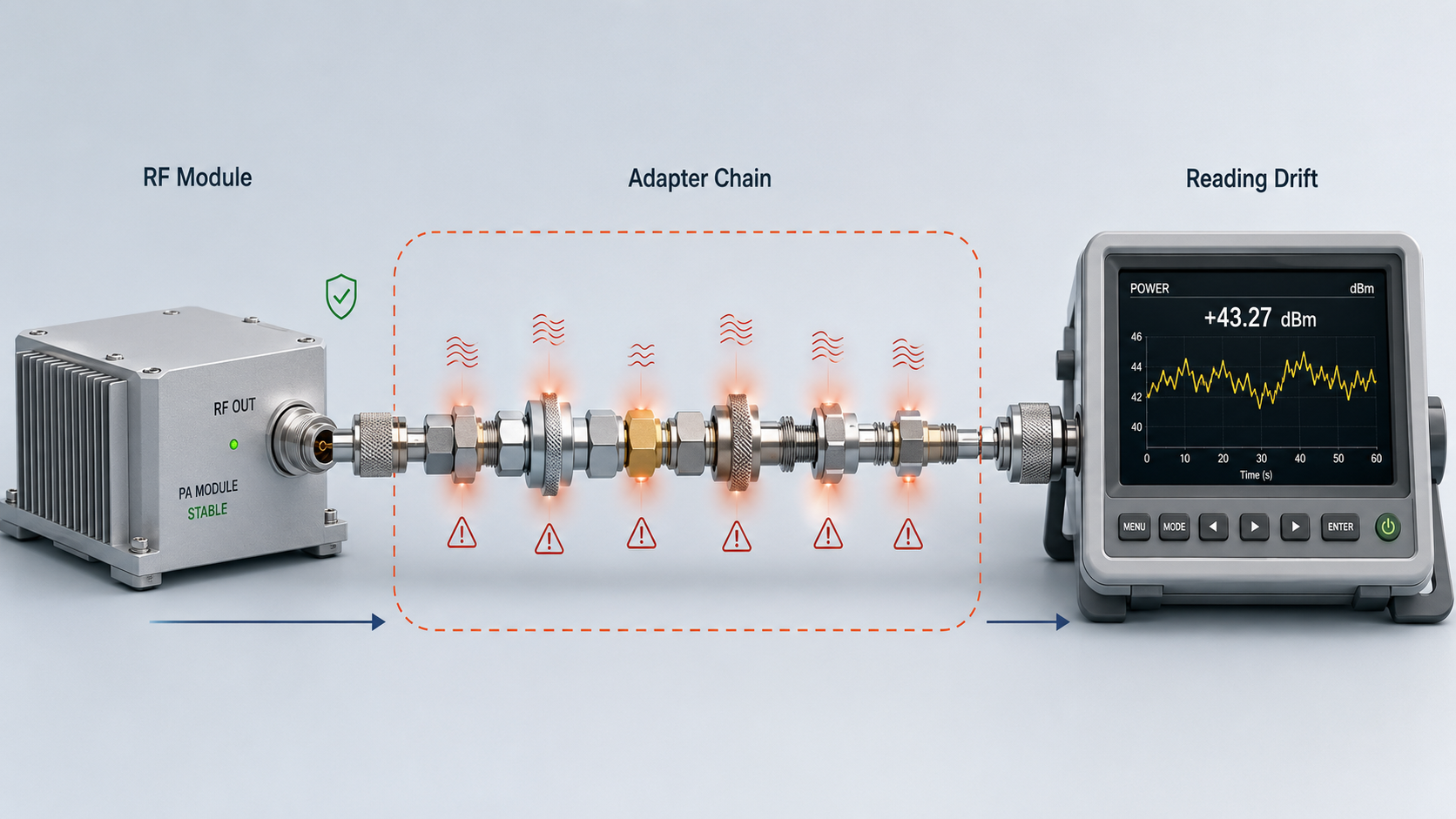
Too many adapters make RF Power Amplifier test data unstable because every adapter adds another RF transition point that can change loss, impedance continuity, contact quality, reflected power, heat behavior, and repeatability. In a C-UAS cabinet, vehicle-mounted jammer, medical RF generator, or factory acceptance bench, the same module may test normally in the morning and show a different reading after the connection path is rebuilt in the afternoon. The RF Power Amplifier may not have changed; the adapter chain may have changed.
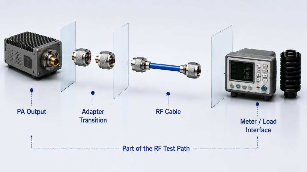
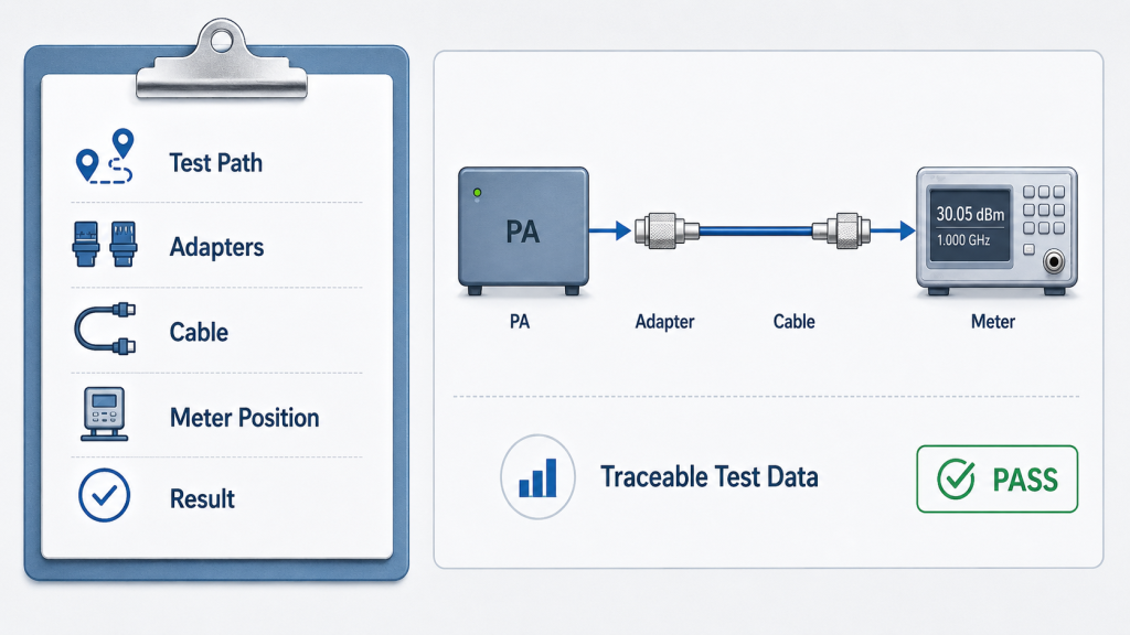
That is why RF Power Amplifier Test Adapter Loss should be treated as part of the validation path, not as a minor accessory issue. A practical test does not stop at the PA output port. It includes the cable, adapter chain, dummy load, power meter position, torque condition, frequency range, and loss compensation method. The goal is not to avoid every adapter. The goal is to prevent temporary RF transitions from becoming hidden variables inside your test result.
1. What Does Adapter Use Mean in RF Power Amplifier Testing?
Adapter use in RF Power Amplifier testing means adding temporary connector transitions between the amplifier output and the measurement equipment. In RF Power Amplifier Test Adapter Loss analysis, these transitions may include N-to-SMA adapters, SMA-to-N adapters, N-type barrel adapters, right-angle adapters, DIN transitions, or short extension connectors used to make a test setup physically fit.
A temporary adapter solves one immediate problem: it helps you connect two ports that do not match. Here’s the engineering point: once that adapter is inside the RF path, it becomes part of the measurement system, not just a mechanical bridge.
Why Is an RF Adapter More Than a Metal Part?
An RF adapter carries RF power, maintains contact pressure, and forms a controlled transition between two connector geometries. If you treat it like ordinary hardware, you may miss why a stable amplifier can produce different readings after a small setup change.
Common adapter-use situations include:
- Module output port does not match the test cable
- Power meter input requires another interface
- Dummy load connector is different from the cable
- Right-angle adapter is added for mechanical clearance
- Several small adapters are stacked because the correct cable is not available
A stable RF system should treat every transition from PA output to the final connector as part of the delivery path, not as a casual accessory. This is the same engineering logic shown in the medical facility RF module application case, where the RF chain was validated from PA output to the final application connector.
Key Takeaway: Adapter use is not automatically wrong, but every adapter must be treated as part of the RF test path because it can affect the measured result.
| Adapter Situation | Engineering Meaning | Test Risk |
|---|---|---|
| One rated adapter | Controlled transition | Usually manageable |
| Several temporary adapters | Multiple RF transitions | Higher uncertainty |
| Unknown adapter rating | Unverified path element | Possible loss or heating |
| Worn adapter | Poor contact condition | Repeatability problem |
| Mixed connector types | Geometry changes | Impedance discontinuity |
This table shows why adapter count and adapter condition should be reviewed before judging amplifier stability.
2. How to Reduce RF Power Amplifier Adapter Errors from Loss
Each adapter adds insertion loss because RF energy must pass through another conductor interface, contact surface, and connector structure. In RF Power Amplifier Test Adapter Loss work, a single adapter may look harmless, but several adapters can add enough loss to change the final power reading.
This matters when you are validating 50W, 100W, or 200W RF Power Amplifier modules. The practical risk is clear: if the test path loss is not understood, you may mistake adapter-chain loss for weak module output.
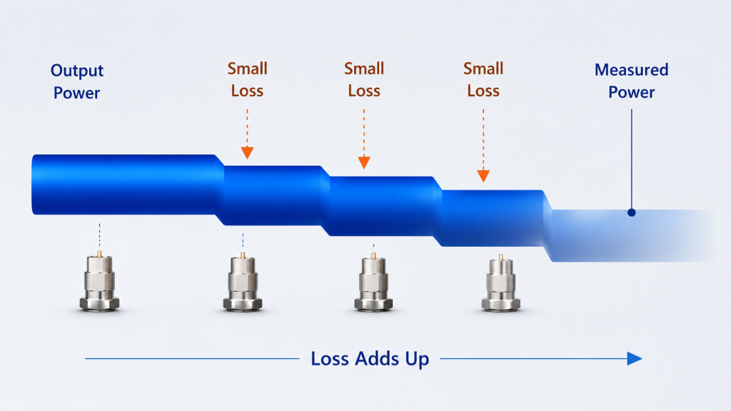
How Can Small Adapter Loss Become Visible?
One high-quality adapter may introduce only a small amount of loss. But a real test path may already include feeder cable loss, connector loss, power meter uncertainty, dummy load interface loss, and calibration position differences.
Before judging output power, you should check:
- Number of adapters in the RF path
- Adapter frequency rating
- Adapter power rating
- Cable type and cable length
- Measurement position
- Whether path loss was compensated
- Whether the same path was used in the previous test
This is why adapter loss should not be reviewed alone. It belongs to the whole RF output chain between the module and the measurement point.
Key Takeaway: Adapter insertion loss can make a healthy RF Power Amplifier look weaker than it is if the test path is not calibrated, compensated, or documented.
| Test Path Element | Possible Effect | What to Check |
|---|---|---|
| RF cable | Attenuation | Length and grade |
| Adapter | Extra insertion loss | Type and rating |
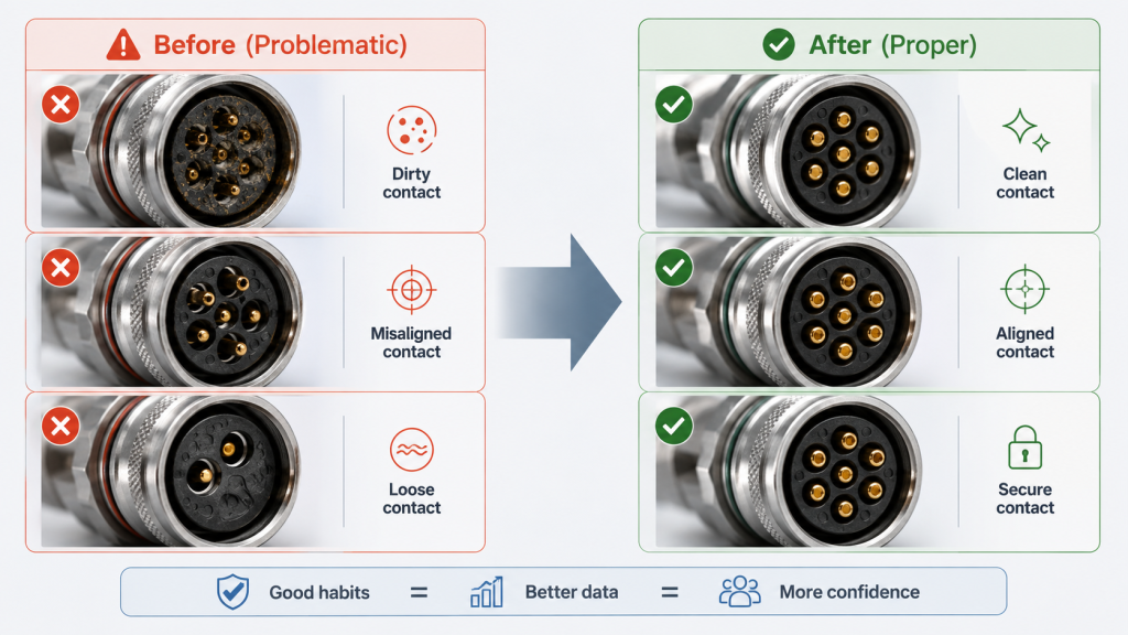
| Connector interface | Contact loss | Cleanliness and torque |
| Power meter input | Position-dependent reading | Calibration point |
| Dummy load port | Final termination condition | Load match and rating |
This table helps separate actual PA output from measurement-path loss.
3. What Causes RF Power Amplifier Adapter Errors in Impedance
Adapter transitions create impedance discontinuity because every transition changes the physical structure of the 50Ω RF path. In RF Power Amplifier Test Adapter Loss review, this discontinuity may show up as reflected power change, VSWR movement, unstable readings, frequency response ripple, or customer retest differences.
A clean RF chain tries to keep a stable impedance path from amplifier output to load. Here’s the field reality: every extra adapter creates another place where geometry, contact alignment, dielectric structure, or mating condition can change.
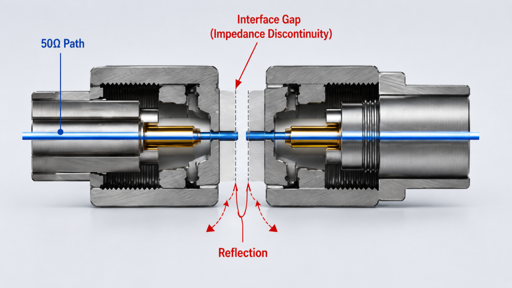
What Changes at the Adapter Interface?
An adapter looks small, but it still has internal RF geometry. If that geometry is poorly matched, worn, contaminated, or stressed by cable bending, the RF path becomes less predictable.
Common discontinuity sources include:
- Center pin alignment error
- Different connector geometry
- Worn threads
- Uneven contact pressure
- Poor plating or oxidation
- Tiny gaps at the mating surface
- Mixed connector standards in one short path
The effect may not look like a complete failure. It may appear as a small change in reflected power or a power reading that refuses to repeat cleanly.
Key Takeaway: More adapter transitions mean more chances for mismatch, reflection, and test instability inside the RF path.
| Transition Issue | Likely Test Symptom | Engineering Concern |
|---|---|---|
| Poor center contact | Reading fluctuation | Unstable continuity |
| Geometry mismatch | VSWR movement | Reflection change |
| Worn thread | Torque inconsistency | Repeatability loss |
| Contaminated surface | Contact resistance | Loss and heating |
| Wrong adapter type | Band-limited behavior | High-frequency error |
This table shows why impedance continuity should be treated as a test-path condition, not only a module-design issue.
4. Why Do Adapter Problems Grow at Higher Frequencies?
Adapter problems grow at higher frequencies because the RF path becomes more sensitive to small geometry, contact, and shielding changes. In RF Power Amplifier Test Adapter Loss analysis, a connector chain that looks acceptable at a lower frequency may become a visible measurement variable at 2.4GHz, 5.8GHz, or wider 2000–6000MHz testing.
This is especially important for wideband RF Power Amplifier modules. Here’s the engineering point: a source factory cannot validate only the PA board itself; it also has to control the cable path, adapter transitions, load condition, and measurement point so engineers can separate real module behavior from adapter-chain error.
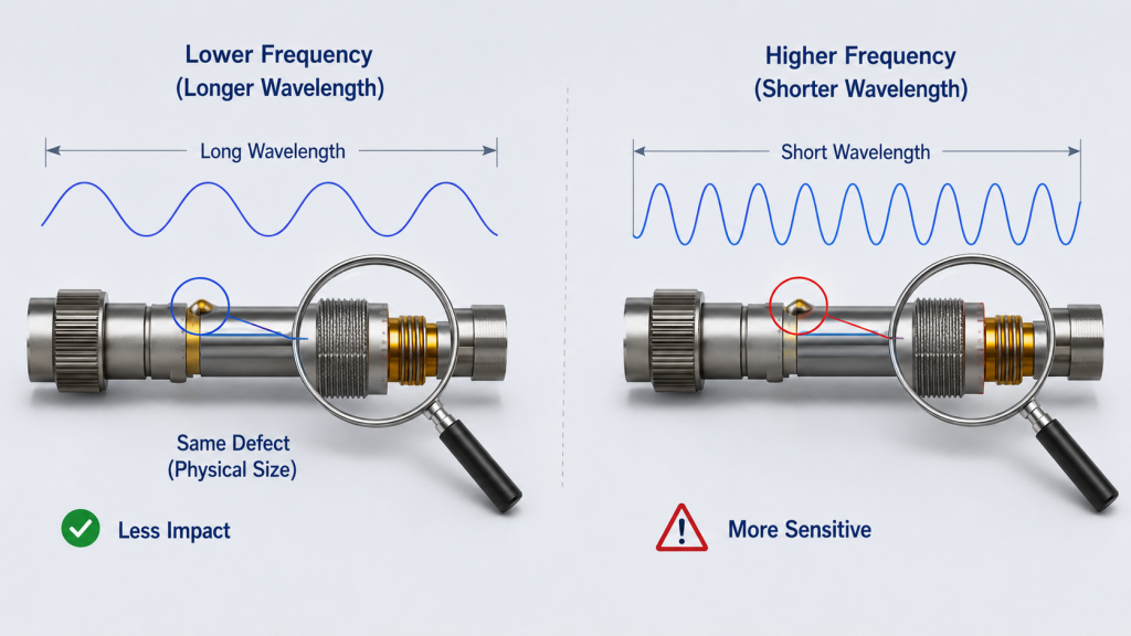
Why Is High-Frequency Testing Less Forgiving?
At higher frequencies, wavelength becomes shorter, and small physical differences matter more. A slightly worn adapter or extra transition may not destroy the test, but it can shift the measured result enough to mislead an acceptance review.
High-frequency adapter risks include:
- Greater sensitivity to connector geometry
- More visible insertion loss
- Higher chance of mismatch-related ripple
- More variation across sweep points
- More need for fixed cable and adapter setup
- More risk from low-grade or unknown adapters
For wideband modules, especially those used in C-UAS systems, the test path must be cleaner because the module is expected to perform across a range, not only at one friendly frequency point.
Key Takeaway: Higher-frequency testing makes adapter count and adapter quality more important because small RF path errors become easier to measure.
| Frequency Condition | Adapter Sensitivity | Test Recommendation |
|---|---|---|
| Lower frequency | Usually less sensitive | Still document adapters |
| Mid-band testing | Moderate sensitivity | Control adapter type |
| 2.4GHz band | Higher sensitivity | Reduce transitions |
| 5.8GHz band | Strong sensitivity | Use rated adapters |
| Wideband sweep | Frequency-dependent | Keep setup fixed |
This table explains why one adapter chain may behave differently across a wide operating range.
5. How to Prevent RF Power Amplifier Adapter Errors in Retests
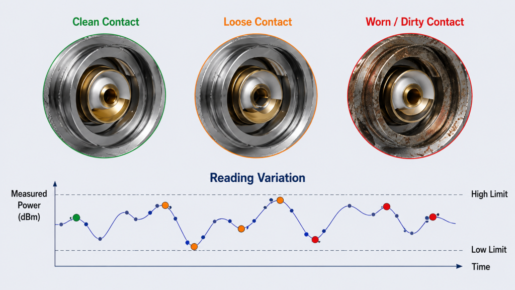
Loose or worn adapters hurt repeatability because they change contact pressure, conductor alignment, and RF continuity from one test to the next. In RF Power Amplifier Test Adapter Loss analysis, this can make a stable RF Power Amplifier look unstable even when the module itself is not the root cause.
This problem is frustrating because it may not repeat in a clean pattern. This is where system integrators should pay attention: if the reading changes after reconnecting the same module, the connector chain deserves inspection before the PA is blamed.
What Makes Adapter Repeatability Poor?
Repeatability problems often come from small mechanical differences. A connector may feel tight but still have poor contact, uneven mating pressure, or internal wear that changes the RF condition.
Common causes include:
- Repeated insertion and removal
- Thread wear
- Center pin damage
- Loose tightening
- Uneven torque
- Dust, oil, or oxidation
- Mixed old and new adapters
- Cable weight pulling on the adapter
In low-altitude security and C-UAS deployments, loose connectors, antenna mismatch, and harsh field conditions can turn small RF path details into hardware risks. On the test bench, the same principle applies: loose transition points create unstable evidence.
Key Takeaway: A worn or loosely tightened adapter can create repeatability problems that look like amplifier instability.
| Adapter Condition | Test Behavior | Corrective Action |
|---|---|---|
| Loose adapter | Reading fluctuation | Retighten with control |
| Worn thread | Inconsistent mating | Replace adapter |
| Damaged center pin | Intermittent contact | Remove from test kit |
| Dirty interface | Loss or heating | Clean and inspect |
| Unknown torque | Poor repeatability | Use a fixed process |
This table gives engineers a practical first check before opening a module failure investigation.
6. What RF Power Amplifier Adapter Errors Affect Customer Retests
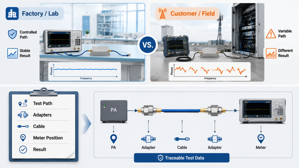
Factory and customer tests are hard to compare when the RF connection paths are different. In RF Power Amplifier Test Adapter Loss review, the factory may use fixed fixtures, short cables, calibrated loads, and known adapters, while the customer may use temporary transitions, different cable grades, another power meter, and another dummy load.
The RF Power Amplifier may be the same, but the measurement path is not. Here’s the practical risk: if both sides only compare the watt number, they may be comparing two different RF systems rather than one module.
What Should Be Compared Before Comparing Power?
A useful comparison starts with the setup, not the final number. If the adapter chain, load, cable, and meter position are different, the test results may not represent the same measurement point.
Compare these items first:
- Module serial number
- Test frequency
- Cable model and length
- Adapter count and type
- Dummy load model
- Power meter position
- Loss compensation method
- DC input voltage
- Ambient temperature
- Test duration
In factory-direct RF module delivery, this is why the test report should not stop at a single watt number. A more useful report explains the load, cable, adapter chain, measurement position, DC input, and test frequency, so the customer can rebuild a comparable setup instead of arguing over two unrelated readings.
Key Takeaway: Factory and customer data should not be compared as raw numbers unless the RF path is also documented.
| Comparison Item | Factory Test | Customer Retest |
|---|---|---|
| Cable path | Fixed and known | May vary |
| Adapter count | Controlled | Often temporary |
| Load condition | Standardized | May differ |
| Meter position | Defined | May shift |
| Loss correction | Recorded | Sometimes missing |
This table shows why traceable test conditions are as important as the output value itself.
7. How Does Adapter Use Affect Long-Duty Testing?
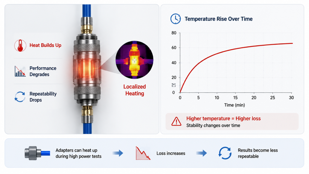
Adapter use affects long-duty testing by turning small contact or rating weaknesses into heat, drift, reflection, or protection events. In RF Power Amplifier Test Adapter Loss work, short low-power checks may look fine, but high-power continuous testing can expose adapter weaknesses quickly.
A high-power RF Power Amplifier does not only test the PA. Here’s the field reality: it also tests every connector, adapter, cable, and load in the output path.
What Can Happen During High-Power Operation?
When RF power stays on for a long period, weak adapter points may heat more than expected. That heat can change contact resistance, shift readings, increase reflected power, or trigger protection logic.
Watch for these symptoms:
- Local adapter heating
- Output reading drift
- Rising reflected power
- Sudden protection alarm
- Load-side temperature abnormality
- Power meter instability
- Connector discoloration after testing
This does not mean every warm adapter is a failure. It means the adapter rating and contact quality must match the power level, frequency range, and test duration.
Key Takeaway: High-power testing makes hidden adapter weaknesses visible through heat, drift, and unstable measurements.
| Long-Duty Symptom | Possible Adapter Cause | What to Check |
|---|---|---|
| Power drift | Contact resistance change | Adapter temperature |
| Reflected power rise | Mismatch at transition | VSWR trend |
| Protection trigger | Poor load path | Adapter and load chain |
| Hot connector | Underrated adapter | Power rating |
| Unstable reading | Intermittent contact | Mating condition |
This table helps prevent engineers from misreading adapter heating as PA thermal instability.
8. How to Reduce RF Power Amplifier Adapter Errors in Test Paths
Engineers should build a cleaner test path by making it short, stable, documented, and repeatable. In RF Power Amplifier Test Adapter Loss control, the best setup is not the one that merely connects; it is the one another engineer can rebuild and verify.
You do not need a complicated process to improve the test. Here’s the engineering point: remove unnecessary transitions before you start interpreting RF output data.
What Should a Cleaner RF Test Setup Include?
A cleaner test path reduces hidden variables and gives the amplifier a fair measurement condition. This is especially useful for system integrators who need to compare factory reports, incoming inspection data, and field retest results.
Useful setup habits include:
- Reduce unnecessary adapters
- Use direct cable interfaces where possible
- Match adapter frequency and power rating
- Remove damaged or unknown adapters
- Keep the same setup for repeated tests
- Record every transition in the report
- Calibrate or compensate key path loss
- Avoid extra transitions at high frequency
For airport and perimeter systems, controlled RF paths matter because protected channels and adjacent sensitive bands leave little room for unstable measurement assumptions. This fits the deployment logic shown in the airport low-altitude security case, where RF behavior, mounting, and field validation all have to be controlled together.
Key Takeaway: A clean RF test path reduces uncertainty before you judge amplifier performance.
| Test Path Practice | Benefit | Result |
|---|---|---|
| Fewer adapters | Less loss uncertainty | Cleaner reading |
| Rated adapters | Safer high-power test | Lower heat risk |
| Fixed cable path | Better repeatability | Easier comparison |
| Recorded setup | Better review | Stronger report |
| Loss compensation | Fairer output data | Less misjudgment |
This table gives a practical checklist for building a test setup that reflects the module instead of the adapter chain.
9. What RF Power Amplifier Adapter Errors Should Reports Record
Adapter details belong in test reports when they affect whether another engineer can repeat the measurement. In RF Power Amplifier Test Adapter Loss work, a power number without the RF connection path is not enough for serious amplifier validation.
You do not need to write a full material list for every small part. This is where the report should be practical: record enough connection detail to explain how the output number was produced.
Which Connection Details Matter Most?
A useful report lets the customer or integrator understand the test environment. If the report only says “100W output,” it leaves too much room for disagreement during retesting.
Record the most relevant items:
- Test frequency or sweep range
- Module output port
- Cable model and length
- Adapter quantity
- Adapter type
- Dummy load model
- Power meter position
- Input power calibration point
- DC input voltage
- Ambient temperature
- Loss compensation method
When integrators need traceable delivery evidence, each unit’s test record should make the RF setup easier to review instead of leaving the connection path unclear. This is especially relevant to high-density security projects like the venue perimeter security case, where integration teams need clear RF control instead of unclear assumptions.
Key Takeaway: A test report becomes more useful when it records the RF path behind the output number.
| Report Item | Why It Matters | Review Value |
|---|---|---|
| Frequency | Loss changes by band | Better interpretation |
| Cable length | Affects measured output | Loss review |
| Adapter count | Adds uncertainty | Repeatability check |
| Load model | Confirms termination | Safer comparison |
| Meter position | Defines measurement point | Fair data review |
This table shows how simple report details can prevent long arguments about whether the PA or the test setup caused a data difference.
10. How Do Experienced Suppliers Reduce Adapter Errors?
Experienced suppliers reduce adapter errors by helping customers separate real module performance from test-path uncertainty. In RF Power Amplifier Test Adapter Loss control, a supplier should help you understand the measured watt number, the RF path behind it, and the practical conditions needed for a fair retest.
A mature RF Power Amplifier supplier should not only say, “the module outputs this power.” The stronger value is explaining how that number was measured and how the customer can rebuild a comparable test path.
What Should a Supplier Help You Clarify?
The supplier should make the test setup easier to repeat and easier to audit. This is not about adding marketing language; it is about reducing hidden variables during system integration and acceptance testing.
A helpful supplier can clarify:
- Output measurement location
- Adapter chain used during factory testing
- Cable and load conditions
- Frequency range tested
- Whether loss compensation was applied
- How the customer should retest
- What symptoms suggest adapter-chain error
- When a module investigation is needed
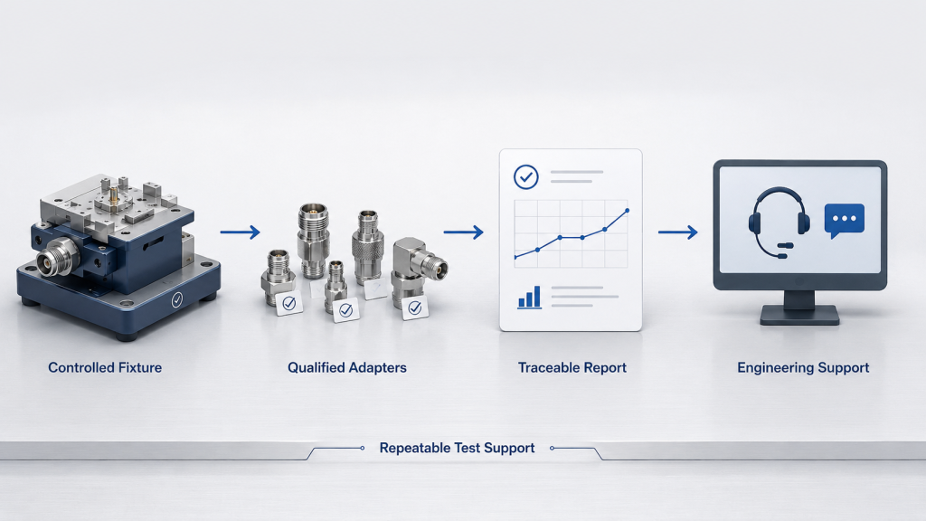
This is where a counter-UAS core component source factory provides value beyond the amplifier module itself. The value is not only the RF board, but also the test discipline behind it: controlled fixtures, known RF paths, practical connector guidance, and traceable data that helps integrators avoid false failure judgment.
Key Takeaway: A good RF Power Amplifier supplier helps customers avoid confusing test-path error with module performance problems.
| Supplier Support Area | Practical Value | Customer Benefit |
|---|---|---|
| Test path documentation | Shows measurement basis | Fair comparison |
| Adapter guidance | Reduces setup error | Better retest |
| Fixed factory fixtures | Improves consistency | Trustworthy data |
| Load condition review | Prevents false faults | Safer validation |
| Integration support | Connects lab to field | Fewer delays |
This table explains why supplier value includes test discipline, not only amplifier hardware.
FAQ
Can I Use Adapters in RF Power Amplifier Testing?
Yes, you can use adapters if they are rated, clean, tight, and documented. The problem is not adapter use itself; the problem is uncontrolled adapter chains that add unknown loss, mismatch, heat, or repeatability error.
What’s the Best Way to Reduce Adapter Test Error?
The best way is to shorten and fix the RF test path. Use fewer adapters, match connector types where possible, choose adapters rated for the test frequency and power, and record the adapter chain in the test report.
How Do I Know If Adapters Are Affecting Output?
You may suspect adapter influence if the same module changes reading after reconnecting, changing torque, replacing an adapter, or moving to another cable path. Check adapter temperature, VSWR trend, insertion loss, and repeatability before assuming the PA is unstable.
Can Adapter Loss Explain Factory and Customer Differences?
Yes, adapter loss can explain part of the difference if the two setups use different cables, adapters, loads, or measurement points. Factory and customer data should be compared only after the RF path conditions are understood.
What’s the Best Report Detail for Adapter Control?
The best report detail is the full RF measurement path. At minimum, include frequency, cable length, adapter count, adapter type, load model, meter position, DC voltage, temperature, and whether loss compensation was applied.
Conclusion
Too many adapters make RF Power Amplifier test data unstable because they turn a simple measurement path into a chain of small RF variables. This article explained how adapter count affects insertion loss, impedance continuity, high-frequency accuracy, repeatability, long-duty heating, factory-versus-customer comparison, and test report quality.
For engineers and system integrators, the practical lesson is simple: control the RF path before judging the amplifier. A stable output number should come from a stable setup, not from a temporary adapter chain that changes every time someone rebuilds the bench. If you need factory-direct RF modules, antennas, SDR sources, and practical support for repeatable C-UAS or RF system integration, contact us today.
Reliable RF validation is not only about reaching power once; it is about proving that the module, the path, and the data can be trusted in real deployment.