


Thermal grease mistakes in RF amplifiers can increase thermal resistance, weaken copper heatsink contact, and reduce long-duty output stability. In a high-power C-UAS cabinet, vehicle-mounted RF system, or sealed industrial RF generator, a module may pass a short bench test but lose output stability during continuous operation if the thermal interface is poorly controlled. A copper heatsink can spread heat efficiently, but it cannot correct trapped air gaps, excessive grease thickness, uneven pressure, or inconsistent assembly. To avoid these problems, engineers need to control grease thickness, contact surface flatness, and mounting pressure as part of the RF module’s thermal design.
That is why RF Power Amplifier Thermal Grease should be treated as part of the RF power path, not as a casual assembly material. Stable long-duty output depends on the GaN device, copper heatsink, flat contact surfaces, controlled grease thickness, and repeatable screw pressure working together. For integrators and technical buyers, this small interface detail can explain why two modules with the same rated power behave differently after 30 minutes, 2 hours, or a full-duty validation cycle.
1.What Is Thermal Grease in RF Power Amplifiers?
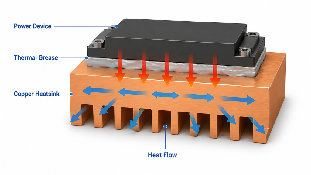
RF Power Amplifier Thermal Grease is a thermally conductive interface material used to fill microscopic gaps between a power device bottom surface and the heatsink. It is not a heatsink material by itself, and it is not meant to replace good mechanical contact. Its job is to reduce the thermal penalty caused by air pockets, surface roughness, and imperfect metal-to-metal contact.
Here’s the engineering point: air is a poor heat conductor, so even a copper heatsink needs a controlled interface layer to perform as expected. In high-power RF modules, the grease layer should support heat transfer without becoming an unnecessary thermal barrier.
What Does Thermal Grease Actually Do?
Thermal grease improves practical contact by filling the tiny voids that remain even after machining. You should see it as a bridge between two solid surfaces, not as the main heat conductor.
Typical functions include:
- Filling surface micro-gaps
- Displacing trapped air
- Improving contact uniformity
- Reducing local hot spots
- Supporting repeatable module assembly
Key Takeaway: Thermal grease helps the heatsink work as designed, but only when the layer is thin, continuous, and controlled.
| Interface Factor | Correct Role | Risk If Misunderstood |
|---|---|---|
| Thermal grease | Fills micro-gaps | Treated as bulk heatsink material |
| Copper heatsink | Spreads heat quickly | Blamed for interface failure |
| Device base | Transfers heat downward | Overlooked during inspection |
| Screw pressure | Controls contact | Applied unevenly |
This table shows why thermal grease should be evaluated as part of the complete heat path, not as an isolated material choice.
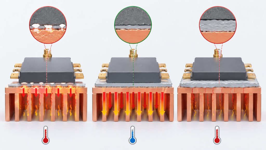
2.Why Does Too Much or Too Little Grease Hurt Cooling?
RF Power Amplifier Thermal Grease hurts cooling when it is too thin to fill surface gaps or too thick to allow efficient heat transfer. A very thin layer may leave dry areas and trapped air, while an excessive layer increases the thermal path length. The best result usually comes from a controlled, uniform layer that is just enough to remove air gaps without forming a thick pad.
The practical risk is clear: “more grease” does not mean “better cooling.” In long-duty RF operation, a thick grease layer can raise device temperature, increase gain drift, and make thermal protection activate earlier than expected.
How Should Engineers Think About Thickness?
Engineers should think about grease thickness as a controlled tolerance, not a visual guess. The aim is full surface coverage with minimal excess.
Useful checks include:
- No dry contact zone
- No large grease ridges
- No thick squeezed edge buildup
- No uneven pressure marks
- No visible contamination
Key Takeaway: The right grease thickness supports a short, stable thermal path from device to copper heatsink.
| Grease Condition | Thermal Effect | Likely RF Result |
|---|---|---|
| Too thin | Air gaps remain | Local hot spots |
| Too thick | Thermal path increases | Earlier power drift |
| Uneven | Heat transfer varies | Batch inconsistency |
| Controlled | Heat flows predictably | Stable long-duty output |
This table gives your assembly team a practical way to connect grease appearance with RF performance risk.
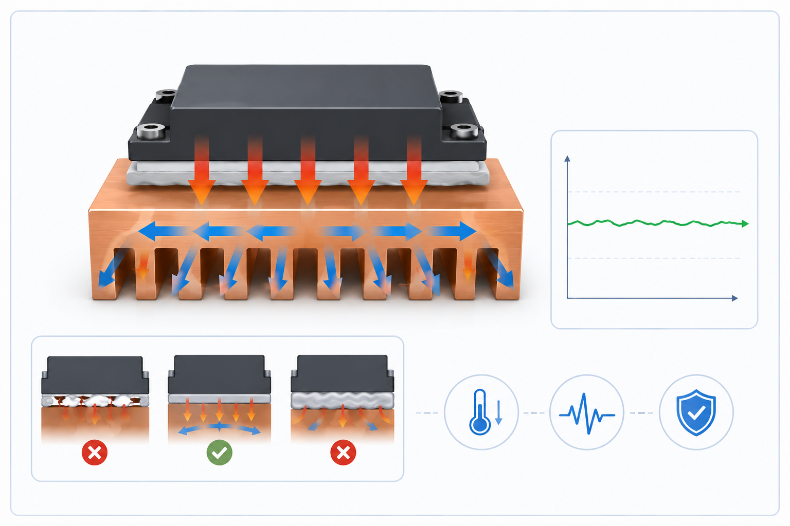
3.How Do Copper Heatsinks Work with Thermal Grease?
RF Power Amplifier Thermal Grease works with copper heatsinks by improving real contact between the power device and the copper surface. Copper has strong thermal conductivity, but it still depends on intimate contact at the device interface. If the grease layer is uncontrolled, the copper may perform well on paper while the device junction still runs hotter than expected.
This is where system integrators should pay attention: the heatsink material is only one part of the cooling system. In applications like medical RF module integration, the thermal interface, cable routing, enclosure design, and repeatable mounting path all affect whether output remains stable inside a compact system.
Why Copper Alone Is Not Enough
Copper spreads heat well, but it cannot eliminate voids caused by uneven surfaces. Thermal grease ensures that the real contact area is closer to the intended contact area.
Important contact factors include:
- Copper surface flatness
- Device base flatness
- Grease spread uniformity
- Mounting pressure sequence
- Surface cleanliness
Key Takeaway: Copper spreads heat, while grease helps heat enter the copper consistently.
| Cooling Element | Main Function | What It Cannot Fix Alone |
|---|---|---|
| Copper heatsink | Spreads heat | Air gaps |
| Grease | Improves contact | Poor heatsink design |
| Flat surface | Reduces voids | Wrong pressure |
| Screw preload | Controls contact | Dirty interface |
This table helps separate heatsink performance from interface performance during troubleshooting.
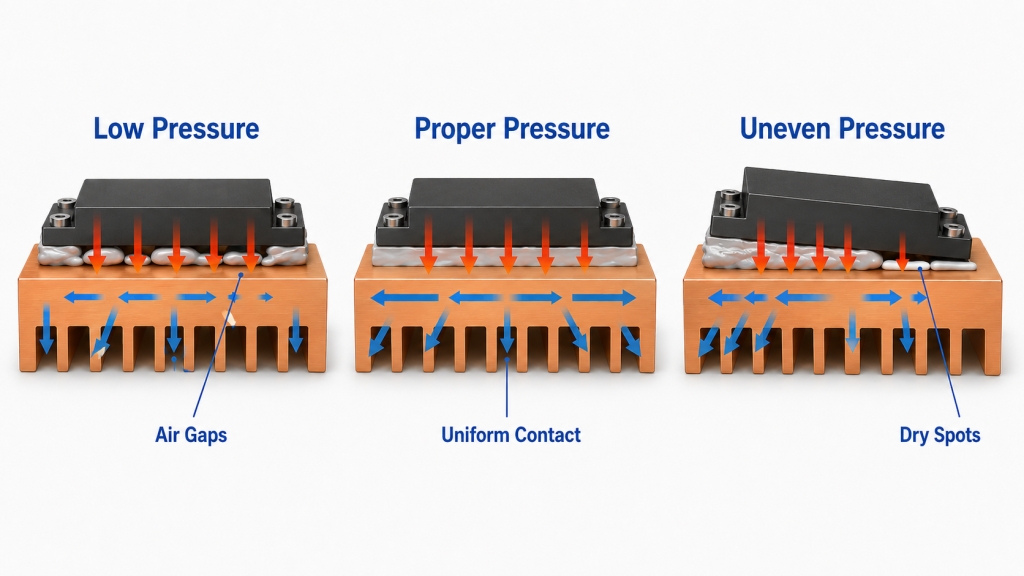
4.How to Apply RF Power Amplifier Thermal Grease Under Proper Pressure
RF Power Amplifier Thermal Grease responds to mounting pressure because pressure determines how evenly the grease layer spreads between the device and heatsink. Too little pressure leaves poor contact and thicker grease pockets. Too much or uneven pressure can squeeze grease away from some areas, creating local dry zones.
Here’s the field reality: pressure is not only about tightening screws harder. It is about using the right screw pattern, torque control, surface flatness, and mechanical support so the interface compresses evenly.
What Should Assembly Teams Control?
Assembly teams should control the pressure process so the interface behaves the same from one module to the next. This matters when you compare prototype samples with batch production units.
Practical controls include:
- Standard screw sequence
- Defined torque range
- Clean contact surfaces
- Consistent grease volume
- Visual edge inspection after tightening
Key Takeaway: Uniform pressure turns thermal grease from a random layer into a repeatable thermal interface.
| Pressure Condition | Interface Result | Performance Risk |
|---|---|---|
| Too low | Poor compression | Hot spots |
| Too high | Grease squeeze-out | Dry contact zones |
| Uneven | Tilted device contact | Thermal imbalance |
| Controlled | Stable layer thickness | Predictable cooling |
This table shows why torque control should be part of RF module thermal validation, not only mechanical assembly.
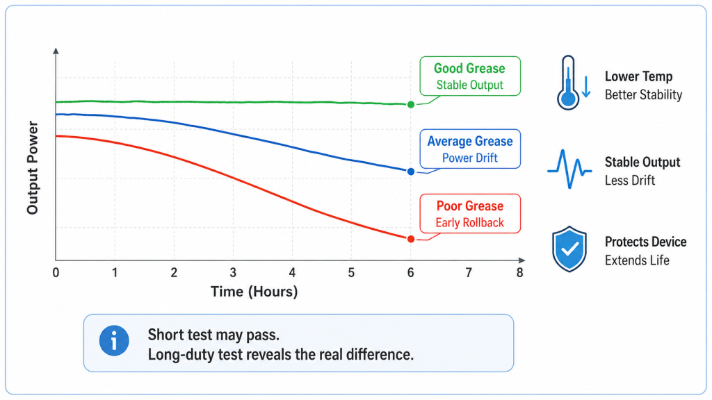
5.How Does Grease Quality Affect Long-Duty Output?
RF Power Amplifier Thermal Grease affects long-duty output because interface resistance becomes more visible as operating time increases. A module may show normal output during a short RF check, but after continuous operation the device temperature can rise enough to shift gain, reduce output, or trigger thermal protection. This is especially important when testing wideband RF Power Amplifier performance across multiple frequencies and power levels.
Here’s the part many buyers miss: short-time power does not prove thermal stability. Long-duty RF output depends on whether the heat path can keep up after the copper, enclosure, and ambient environment reach real operating temperature.
What Changes During Continuous Operation?
During continuous operation, heat accumulates through the device, interface, heatsink, enclosure, and airflow path. A weak interface may not fail immediately, but it can gradually reduce thermal margin.
Watch for:
- Output drop after warm-up
- Faster temperature rise
- Earlier alarm activation
- Gain drift at band edges
- Different behavior between modules
Key Takeaway: A good thermal interface protects continuous RF output, not just first-minute test results.
| Test Stage | What It Shows | Interface Risk Revealed |
|---|---|---|
| First minute | Basic function | Usually limited |
| 10–20 minutes | Warm-up behavior | Early drift |
| 60 minutes | Thermal balance trend | Interface weakness |
| Full-duty cycle | Real stability | Protection behavior |
This table explains why continuous RF testing is necessary when judging thermal grease performance.
6.How Does Assembly Consistency Affect Batch Results?
RF Power Amplifier Thermal Grease affects batch results because small differences in thickness, pressure, and spread pattern can create different thermal behavior across units. One sample may pass easily, while another unit from the same design may show earlier thermal drift if the interface process is not controlled. For technical buyers, this is a batch consistency issue, not just a workmanship detail.
This is where factory process control matters. If CNC heatsink flatness, grease application, screw pressure, and long-duty testing are managed together, the buyer receives modules that behave predictably instead of depending on the best individual sample.
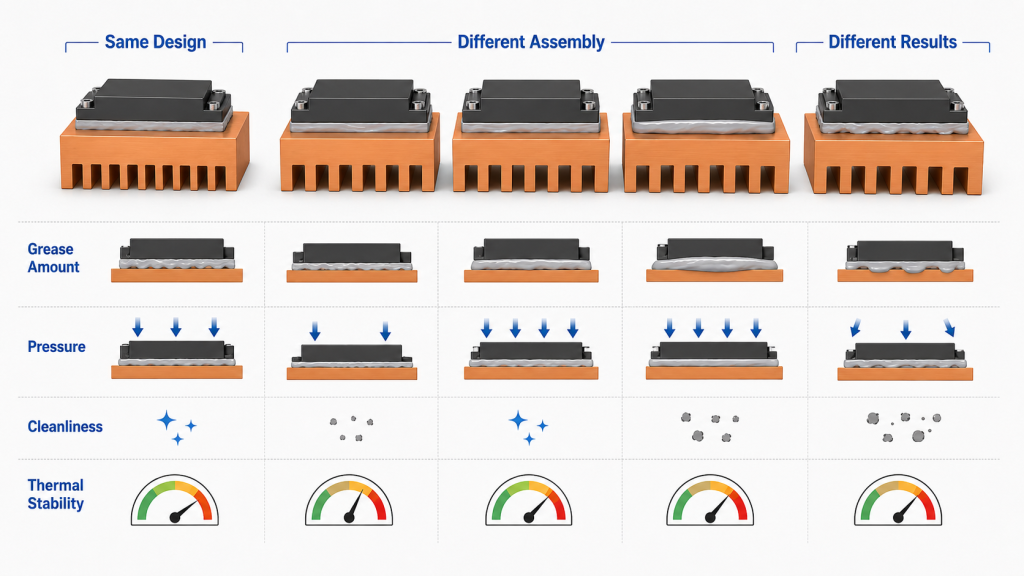
What Causes Unit-to-Unit Variation?
Variation usually comes from process differences that are small visually but large thermally. These differences often appear only after extended output testing.
Common causes include:
- Manual grease over-application
- Uneven screw tightening
- Surface contamination
- Inconsistent device seating
- Different heatsink flatness quality
Key Takeaway: Batch consistency depends on repeatable thermal interface control from assembly to test.
| Variation Source | Immediate Appearance | Long-Duty Effect |
|---|---|---|
| Grease volume | Slight edge difference | Temperature spread |
| Screw pressure | Looks assembled | Uneven contact |
| Surface dirt | Hard to notice | Local hot spot |
| Flatness drift | May pass visually | Higher thermal resistance |
This table helps procurement teams ask process questions before accepting batch production.
7.Where Can Auxiliary Grease Help Inside RF Modules?
RF Power Amplifier Thermal Grease can also support secondary heat paths when small devices, inductors, shields, or auxiliary components need controlled heat transfer. These areas should not receive random excess grease. They may need small amounts of grease, thermal pads, or designed contact points depending on mechanical clearance and heat load.
Here’s the engineering point: auxiliary thermal material should support the main thermal design, not hide a layout problem. In C-UAS RF modules, the highest heat path still comes from the power device to the copper heatsink, while secondary materials help reduce smaller hot spots across the assembly.
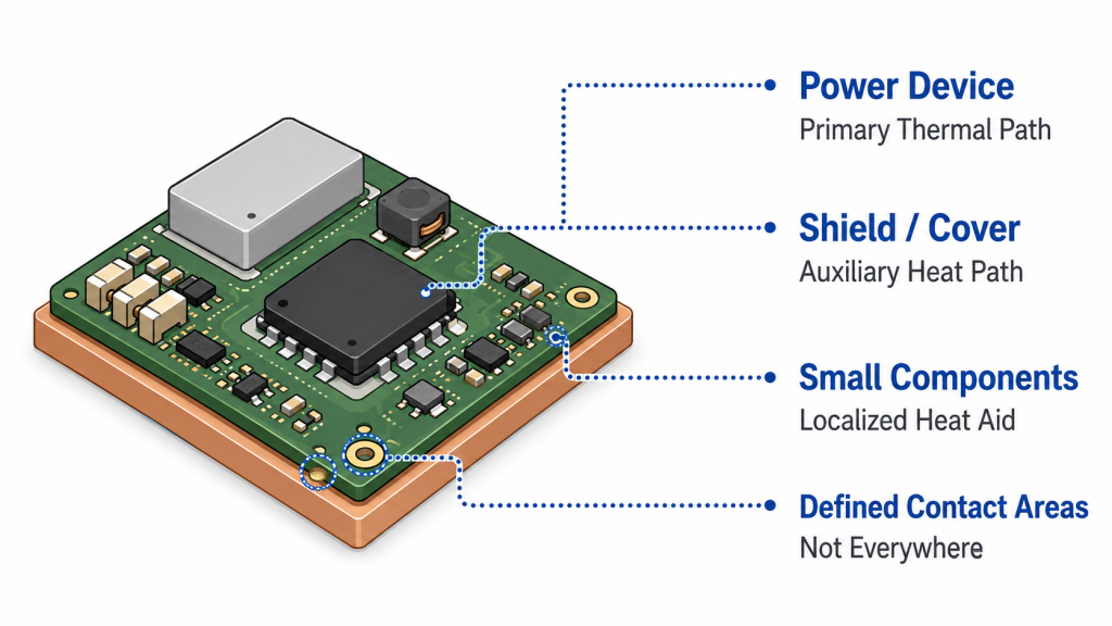
How Should Auxiliary Usage Be Controlled?
Auxiliary grease or pads should be applied only where the mechanical design requires them. Random use can contaminate RF areas, affect serviceability, or create uncertain assembly thickness.
Control points include:
- Defined contact locations
- Small material amount
- No contamination near RF connectors
- Compatible thermal pad thickness
- Clear inspection standard
Key Takeaway: Auxiliary grease can help thermal distribution, but it should never replace a defined primary heat path.
| Application Area | Suitable Material | Main Concern |
|---|---|---|
| Power device base | Thin grease layer | Contact resistance |
| Small hot component | Grease or pad | Clearance control |
| Shield contact area | Pad if needed | Compression height |
| RF connector area | Usually avoid grease | Contamination risk |
This table separates useful auxiliary thermal support from uncontrolled material use.
8.How to Apply RF Power Amplifier Thermal Grease Correctly
RF Power Amplifier Thermal Grease should be applied as a thin, even layer that covers the required contact area without excessive buildup. The goal is not to make the surface look heavily coated. The goal is to remove air pockets while keeping the shortest practical thermal path between device and heatsink.
This is where a simple process becomes valuable: use repeatable application volume, controlled spreading, clean tooling, and a defined screw-tightening sequence. If your team cannot repeat the interface, your long-duty RF results may not repeat either.
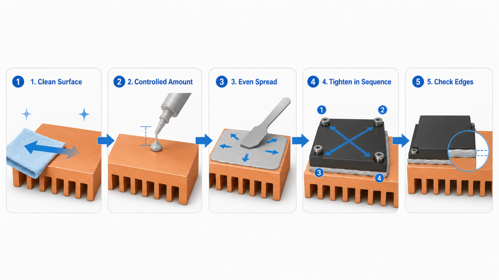
What Is a Practical Application Checklist?
A practical checklist helps technicians repeat the same interface quality across prototypes and production. It also gives engineers a reference when reviewing failed thermal tests.
Check before closing the module:
- Clean both contact surfaces
- Apply controlled grease amount
- Spread evenly across contact area
- Tighten screws in sequence
- Inspect edge squeeze-out
Key Takeaway: Controlled application makes thermal grease a predictable engineering variable, not a hidden assembly risk.
| Process Step | Good Practice | Warning Sign |
|---|---|---|
| Cleaning | Dry, clean surface | Dust or residue |
| Application | Thin continuous layer | Thick ridges |
| Mounting | Even seating | Tilted device |
| Tightening | Torque sequence | Random screw order |
| Inspection | Light edge trace | Heavy overflow |
This table can be used as a simple production-side guide for thermal interface control.
9.How to Test RF Power Amplifier Thermal Grease Performance
RF Power Amplifier Thermal Grease should be evaluated through temperature and RF output data during long-duty testing. Visual inspection alone cannot prove that the interface is performing correctly. Engineers should compare module base temperature, heatsink temperature, output power, DC input, and alarm behavior over time.
Here’s the practical risk: if you only record output power at the start of the test, you may miss thermal drift that appears after the module reaches steady-state temperature. A good test log connects RF performance with the thermal path.
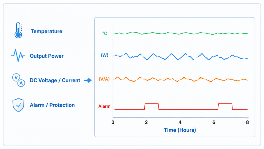
Which Measurements Matter Most?
The most useful measurements show whether heat transfer is stable and whether RF output remains predictable under load. You do not need a complicated setup if the test points are consistent and repeatable.
Monitor:
- Module bottom temperature
- Copper heatsink temperature
- Ambient temperature
- RF output power
- DC current and voltage
- Alarm or protection status
Key Takeaway: Thermal interface quality becomes clear when temperature trends and RF output trends are reviewed together.
| Data Point | Why It Matters | What to Watch |
|---|---|---|
| Module base temp | Shows device-side heat | Rapid rise |
| Heatsink temp | Shows spreading effect | Slow heat transfer |
| Output power | Shows RF stability | Downward drift |
| DC input | Shows electrical load | Current change |
| Alarm status | Shows protection behavior | Early trigger |
This table helps engineers move from visual judgment to measurable thermal interface validation.
10.How Do Experienced Suppliers Control Thermal Interface?
RF Power Amplifier Thermal Grease is controlled by experienced suppliers through repeatable machining, assembly, pressure control, and long-duty validation. A source factory should not rely only on a clean-looking prototype. It should prove that the same interface can be repeated across production and verified with test data.
This matters for integrators working on C-UAS, medical RF, border security, or critical infrastructure systems where downtime is costly. A supplier with in-house CNC thermal design, controlled assembly, and RF test capability can connect mechanical interface quality with full-band output behavior and project-level reliability, as shown in critical infrastructure RF security deployments.
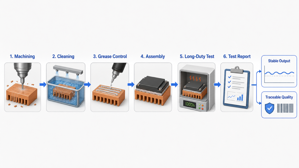
What Should Buyers Ask Before Procurement?
Buyers should ask whether the supplier controls both the thermal interface process and the RF validation process. A datasheet power number is not enough if the module cannot repeat that output after thermal stress.
Useful questions include:
- Is the heatsink surface CNC-controlled?
- Is grease application standardized?
- Is torque or pressure controlled?
- Is long-duty output tested?
- Is test data traceable to each unit?
Key Takeaway: A capable supplier controls the thermal interface as part of RF performance, not as a final assembly detail.
| Supplier Control | Buyer Benefit | Risk If Missing |
|---|---|---|
| CNC thermal design | Better contact repeatability | Random heat path |
| Standard grease process | Stable batch behavior | Unit variation |
| Long-duty RF test | Real output confidence | Short-test illusion |
| Traceable report | Easier verification | Unclear failure source |
This table shows why thermal interface control should be included in RF module supplier evaluation.
FAQ
Can I apply more thermal grease for safer cooling?
No, more thermal grease is not automatically safer. Excess grease can increase thermal resistance, create uneven thickness, and make long-duty output less stable.
What’s the best thermal grease thickness for RF modules?
The best thickness is the thinnest continuous layer that fills surface micro-gaps without creating a thick barrier. The exact value depends on device package, flatness, pressure, and assembly design.
How do I know if grease is causing power drift?
You know by comparing temperature rise, output power, DC current, and alarm timing during continuous operation. If short tests pass but long-duty output drops, the interface should be checked.
Can a copper heatsink compensate for bad grease application?
No, a copper heatsink cannot fully compensate for a poor thermal interface. Copper spreads heat well only after heat successfully transfers from the device into the heatsink.
What’s the best way to control batch consistency?
The best way is to standardize grease volume, contact surface cleaning, torque sequence, and long-duty test logging. Batch consistency comes from process control, not visual inspection alone.
Conclusion
Thermal grease thickness may look like a small assembly detail, but it can directly affect RF Power Amplifier cooling, continuous output stability, thermal protection behavior, and batch consistency. This article covered what grease does, why too much or too little creates risk, how copper heatsinks depend on real contact, how pressure affects the interface, and what data engineers should monitor during long-duty testing.
For high-power RF modules used in C-UAS, medical RF platforms, vehicle-mounted systems, and critical infrastructure projects, we can help with CNC-controlled thermal design, repeatable assembly processes, full-band RF validation, and reviewable test data. If you need factory-direct RF modules with controlled thermal paths and predictable long-duty performance, contact us today.
A reliable RF system is not built from rated power alone; it is built from every controlled interface that keeps power stable under real operating stress.