


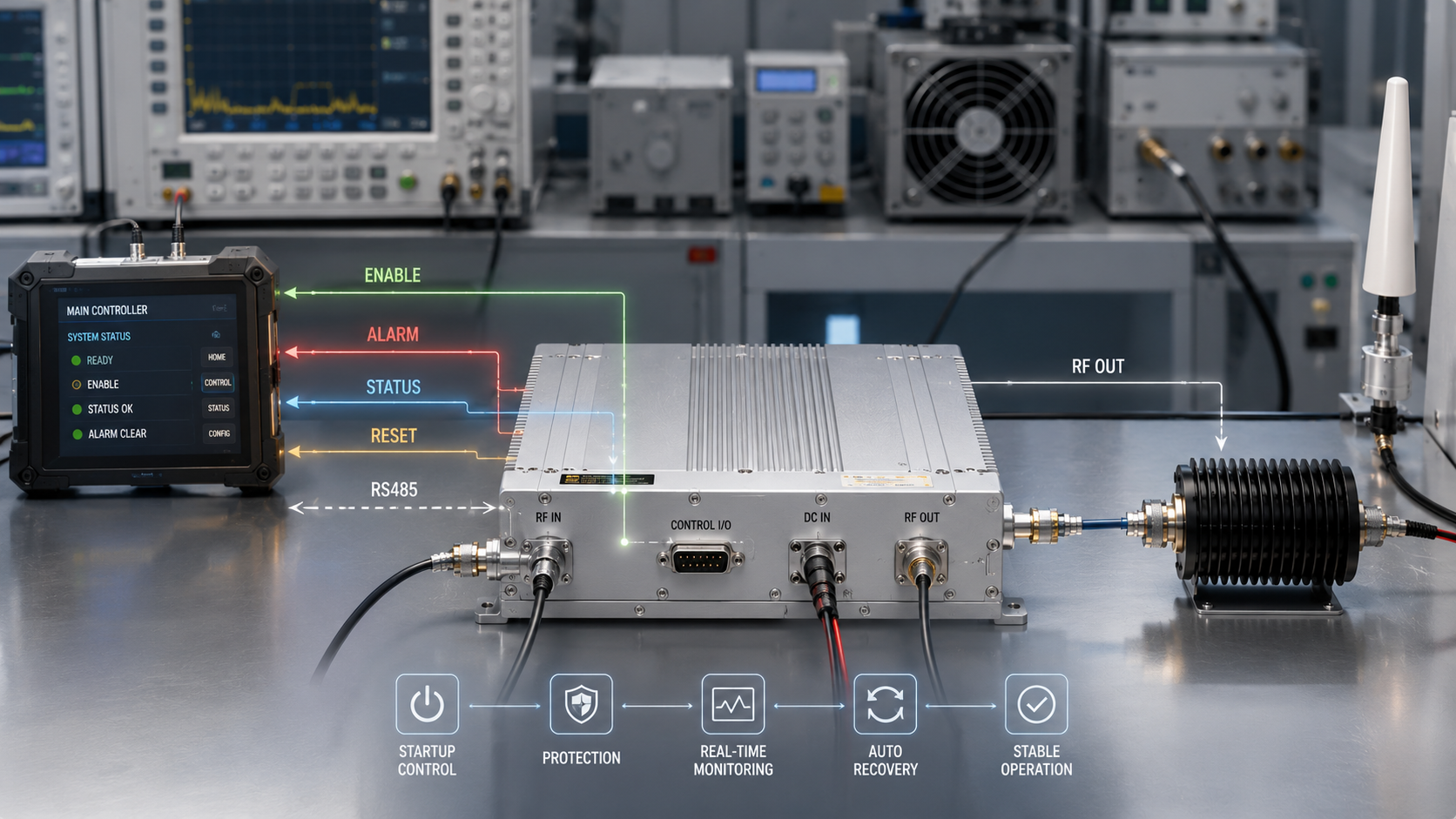
RF Power Amplifier control logic matters because it decides when a module can start, why it stops, how it reports faults, and how it returns to service inside a full RF system. In a real cabinet, vehicle platform, airport perimeter system, or OEM device, a tested RF Power Amplifier can still slow integration if Enable, Alarm, Status, Reset, power adjustment, communication, wiring, and protection behavior are not defined before system testing. Here’s the deal: interface pins are only useful when your controller knows what each signal means and what action should follow.
A system integrator may think the module has failed when the real issue sits in control logic. Enable may be blocked because DC voltage has not stabilized. Alarm may appear because VSWR protection reacted correctly. Status may be unreadable because the main controller uses the wrong address or polling cycle. Reset may not work because recovery behavior was never agreed. This article explains how RF Power Amplifier control logic reduces integration delay, false troubleshooting, and late-stage wiring changes.
1. How to Define RF Power Amplifier Control Logic Before Integration
RF Power Amplifier control logic means the agreed behavior behind each control signal inside a complete system. It defines when the module may turn on, what fault state means, how the main controller reads operating data, and how recovery should happen after protection. What’s the real story? A control interface tells you what pins exist, but control logic tells your system what to do with them.
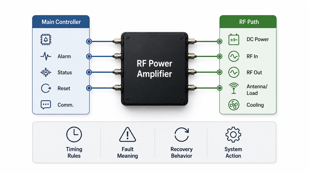
What Makes Logic Different From a Pin List?
A pin list only describes electrical access, while logic describes system behavior. You may have Enable, Alarm, Status, Reset, TTL, RS485, or D-Sub signals, but your project still needs rules for timing, fault meaning, recovery, and controller response.
● Enable must follow system readiness
● Alarm must describe fault meaning
● Status must be readable by the controller
● Reset must follow a safe recovery rule
● Communication must match the control architecture
Key Takeaway: You reduce integration risk when every RF control signal has a defined system action, not only a connector label.
| Control Area | Weak Definition | Better System Logic |
|---|---|---|
| Enable | High level turns output on | Power, signal, load, and protection states are checked |
| Alarm | General fault only | Fault category guides the next action |
| Status | On/off feedback | Controller reads useful operating values |
| Reset | Random restart | Defined recovery path after protection |
This turns an RF module from a passive power block into a controllable subsystem.
2. How to Implement RF Power Amplifier Enable and Reset Logic Safely
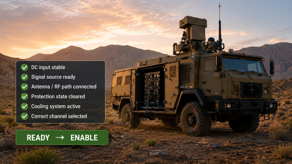
RF Power Amplifier Enable control is not enough when it works as a simple on/off command without system readiness checks. High-power RF output should not start before DC voltage, signal input, antenna load, cooling, and protection states are ready. This is where it gets practical: an unclear Enable sequence can make a healthy module look unstable during system commissioning.
When Should Enable Be Allowed?
Enable should be allowed only after the main controller confirms safe startup conditions. In vehicle-mounted, fixed-site, and multi-channel C-UAS systems, one premature Enable signal can create alarms, reflected power events, or confusing output behavior before the RF path is ready.
● DC input has reached stable voltage
● Signal source has locked or reached valid state
● Antenna, dummy load, or RF path is connected
● Protection state has cleared
● Cooling path is active
● Correct channel has been selected
Key Takeaway: Enable should follow system readiness, not only a voltage level on one control pin.
| Enable Condition | Why It Matters | Risk If Missing |
|---|---|---|
| DC stability | Prevents false startup | Output drop or voltage alarm |
| RF load ready | Reduces mismatch risk | VSWR or reflected power fault |
| Signal source ready | Avoids abnormal amplification | Unstable output behavior |
| Protection cleared | Stops repeated restart loops | Confusing Alarm cycles |
A defined Enable sequence gives your controller a clear reason for allowing or blocking RF output.
3. What RF Power Amplifier Alarm Signals Should Tell Your Controller
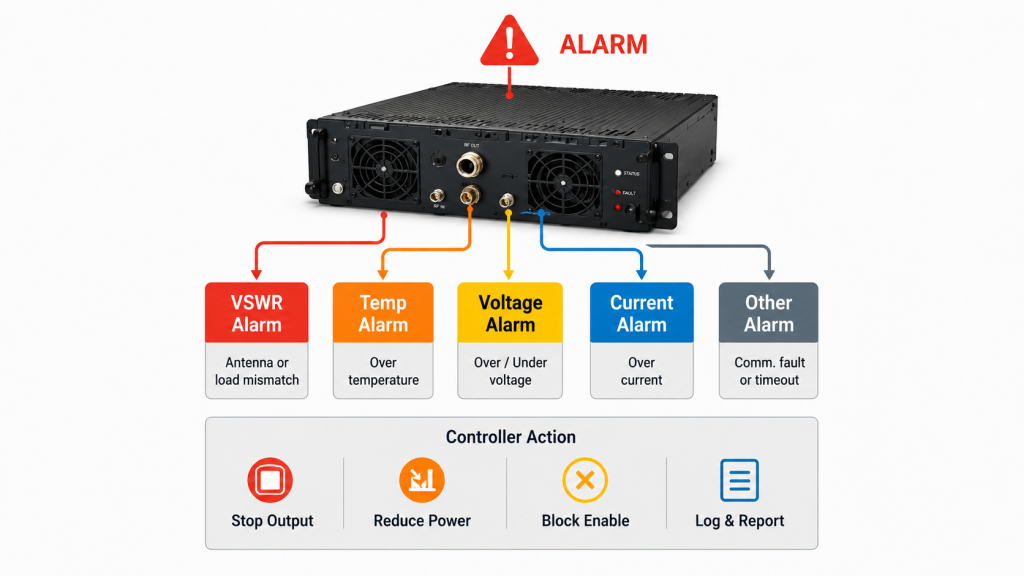
RF Power Amplifier Alarm signals should be defined by fault category before system testing begins. A combined Alarm output can tell the controller that something went wrong, but it may not explain whether the issue came from VSWR, temperature, voltage, current, input drive, or shutdown state. Here’s the catch: if Alarm has no meaning, engineers must troubleshoot too many possible causes at once.
What Should Alarm Tell Your Controller?
Alarm should help the main controller decide the next action. In one OEM integration scenario, the RF core became easier to manage after its operating state was made readable for the main controller, which matches the same idea: the controller should not guess why an RF section stopped.
● VSWR or reflected power alarm
● Over-temperature alarm
● Over-voltage or under-voltage alarm
● Over-current alarm
● Shutdown or latched protection state
● Communication fault or control timeout
In factory-direct RF module projects, alarm and status definitions should be discussed before system wiring. The controller needs to know why the RF channel entered protection, not only that it stopped. The RF core should expose usable operating states so system engineers can connect protection behavior with controller logic.
Key Takeaway: Alarm feedback should explain the protection event, not only report that the module stopped.
| Alarm Type | Likely Cause | Better Controller Action |
|---|---|---|
| VSWR | Antenna or load mismatch | Stop output and check RF path |
| Temperature | Cooling or duty stress | Reduce power or pause channel |
| Voltage | DC supply condition | Block Enable until voltage stabilizes |
| Current | Load or internal stress | Shut down affected channel |
A useful Alarm definition turns fault handling into a controlled engineering process.
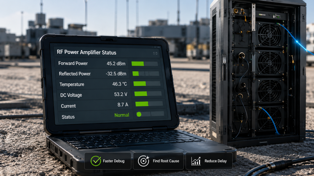
4. How to Use RF Power Amplifier Status Feedback to Reduce Troubleshooting
RF Power Amplifier Status feedback speeds debugging because it changes the module from a black-box power stage into a readable RF subsystem. Without status data, your controller may only know that output dropped or Alarm appeared. You might be wondering: what should the engineer check next? Status feedback shortens that path.
Which Status Values Help Most?
The most useful Status values are the ones that separate a real module fault from a system condition. If output is low, the controller should help you see whether the module is disabled, protected, overheated, under-voltage, mismatched, or not communicating.
● Enable state
● RF output state
● Forward power
● Reflected power
● DC voltage
● Current draw
● Module temperature
● Communication health
Key Takeaway: Status feedback helps your team diagnose RF behavior with evidence instead of repeated manual checks.
| Symptom | Status Value to Read | Likely Direction |
|---|---|---|
| No output | Enable state | Control sequence issue |
| Alarm active | Fault category | Protection source |
| Output drops | Forward power and voltage | RF path or DC supply issue |
| Hot module | Temperature | Cooling or duty-cycle issue |
Readable Status data reduces blind troubleshooting during factory acceptance, field installation, and maintenance.
5. How Does RF Power Amplifier Reset Logic Affect Recovery?
RF Power Amplifier Reset logic affects recovery because it decides whether a protection event becomes controlled behavior or a field troubleshooting problem. A module may protect itself correctly after VSWR, heat, voltage, or current stress, yet the system may still look unreliable if the recovery path is unclear. The practical issue is simple: operators need to know how the system returns to service.
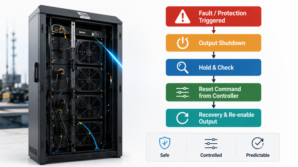
Should Recovery Be Automatic or Controller-Based?
Recovery may be automatic, manual, controller-commanded, or power-reduced depending on project risk. For high-power RF modules with VSWR mismatch protection and dynamic temperature monitoring, Reset and Status logic should work together so the controller knows whether to restart, wait, reduce power, or keep one channel offline.
● Auto recovery after mild temporary fault
● Latched fault after severe protection event
● Controller Reset after inspection
● Power reduction during thermal stress
● Single-channel shutdown in multi-module systems
● Operator notice after repeated alarms
Key Takeaway: Reset logic prevents random power cycling and gives maintenance teams a safer recovery method.
| Recovery Mode | Best Fit | Risk If Undefined |
|---|---|---|
| Auto recovery | Temporary mild fault | Unexpected restart |
| Latched state | Severe protection event | Manual delay if not planned |
| Power reduction | Thermal stress | Output uncertainty |
| Channel shutdown | Multi-band cabinet | Wrong channel may stay offline |
Recovery logic should match system risk rather than depend on repeated power-off and power-on attempts.
6. What Communication Protocols Ensure RF Power Amplifier Integration Success
RF Power Amplifier communication should match the main controller because protocol support alone does not make integration fast. RS485, Modbus, TTL, Ethernet, AT commands, or D-Sub lines only help when the controller can read the right values, send the right commands, and handle timeouts correctly. Here’s the business reality: communication should fit the system architecture, not force the controller team to redesign late.
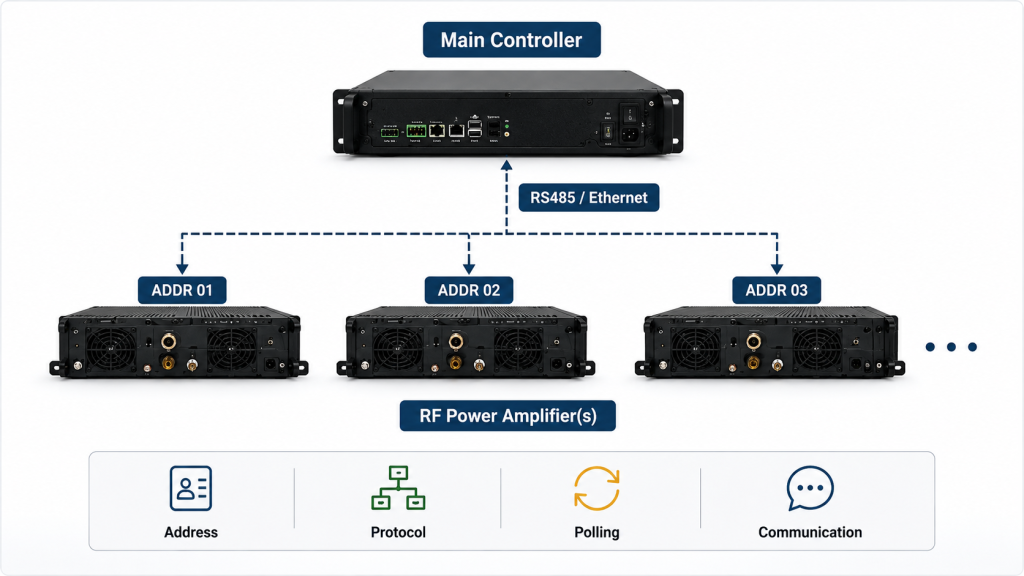
What Should Be Confirmed Before Software Work?
Engineers should confirm protocol, command list, address allocation, polling cycle, response timing, power adjustment rules, and communication-failure behavior before software integration. In fast-moving defense and C-UAS projects, standard command logic can reduce software friction when hardware and controller teams agree early.
● Protocol type and baud rate
● Register map or command list
● Address allocation for multiple modules
● Read cycle and timeout logic
● Power adjustment range
● Alarm readback method
● Communication loss response
Key Takeaway: Communication logic works best when it fits your controller workflow before firmware, harnesses, and test plans are frozen.
| Communication Item | Question to Confirm | Why It Helps |
|---|---|---|
| Protocol | RS485, Modbus, TTL, Ethernet, or AT command? | Avoids controller mismatch |
| Address | One module or multiple modules? | Prevents channel confusion |
| Polling cycle | How often should data update? | Reduces stale status |
| Timeout behavior | What happens if communication fails? | Keeps system predictable |
Clear communication mapping helps RF hardware and system software work as one controlled platform.
7. What Multi-Module RF Power Amplifier Logic Needs for C-UAS Systems
RF Power Amplifier logic changes in multi-module systems because every channel needs its own readable state and coordinated action. In multi-band low-altitude security systems, each RF channel needs clear enable, alarm, and recovery logic so the controller can manage the complete C-UAS RF chain. Now the problem becomes wider: one channel fault should not confuse the whole cabinet.
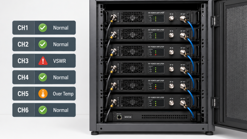
What Becomes Harder with Several RF Channels?
A vehicle-mounted or fixed-site C-UAS system may include multiple RF channels for different frequency ranges, antennas, or coverage zones. For vehicle-mounted and fixed-site C-UAS systems, RF SKYPOWER’s wideband RF modules are often integrated as multiple controlled RF channels rather than one isolated power block. That means Enable sequence, Alarm feedback, channel Status, and recovery behavior should be planned with the main controller before final cabinet wiring.
● All modules may need different Enable timing
● One channel Alarm may not require full-system shutdown
● High temperature may require partial derating
● Main UI must show each channel clearly
● Service teams need fast channel identification
● Power startup may need sequence control
Key Takeaway: Multi-module logic helps your team locate one channel issue without treating the whole RF system as failed.
| Multi-Module Issue | Logic Needed | User Benefit |
|---|---|---|
| One channel alarm | Per-channel fault identity | Faster repair |
| Shared DC supply | Startup sequence | Lower surge risk |
| Cabinet heat | Derating rule | More stable service |
| Mixed bands | Channel mapping | Clear operator view |
8. How Can Poor RF Power Amplifier Logic Create False Faults?
RF Power Amplifier logic can create false faults when controller behavior, wiring, and protection rules are not aligned. A module with no RF output may not be broken. Here’s a common trap: Enable may be blocked, Reset may not have been triggered, or Status polling may use the wrong address.
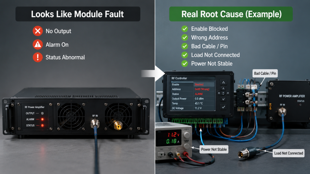
Which False Problems Slow Integration?
Many integration delays look like amplifier defects at the beginning. After review, teams often find a control-path issue, load condition, wiring mismatch, or communication setting rather than a failed RF stage.
● No output caused by unmet Enable condition
● Alarm caused by antenna or dummy-load mismatch
● No recovery caused by missing Reset command
● Missing Status caused by protocol mismatch
● Wrong channel caused by address mapping error
● Repeated shutdown caused by undefined recovery rule
For critical infrastructure deployments, unclear alarm and recovery logic can slow down maintenance because operators need to know whether the RF chain is protected, offline, or ready to restart.
Key Takeaway: Poor logic can make a healthy RF module look unreliable during integration.
| False Fault | Real Cause May Be | Better Check |
|---|---|---|
| No RF output | Enable not allowed | Read startup condition |
| Alarm active | Load mismatch | Check reflected power or VSWR state |
| No restart | Reset not defined | Confirm recovery rule |
| Status missing | Protocol mismatch | Verify address and command map |
This is why control-chain checks should sit beside RF-chain checks during system validation.
9. What RF Power Amplifier Logic Should Be Confirmed Before Production?
RF Power Amplifier control logic should be confirmed before production because late interface changes affect wiring, firmware, test flow, and field service. A small change in Alarm meaning or Reset behavior can force harness updates, controller edits, new test scripts, and extra acceptance work. The good part: a simple confirmation checklist can prevent long rework.
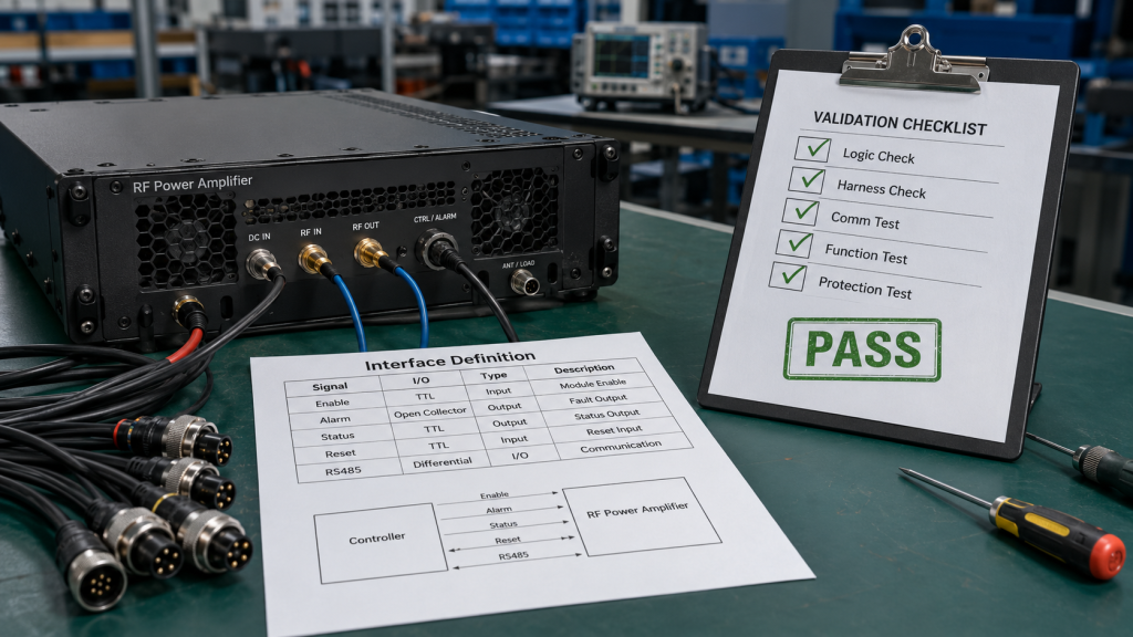
What Should Your Engineering Checklist Include?
Before batch assembly, your team should confirm startup logic, fault classification, readable data, recovery behavior, communication plan, address allocation, harness pinout, signal level, protection response, and acceptance test steps. This checklist should be reviewed by RF engineers, controller engineers, wiring engineers, and the final integrator.
● Enable condition and timing
● Alarm categories
● Status feedback map
● Reset and recovery rules
● Communication protocol
● Channel address plan
● Harness definition
● Control signal levels
● Protection test method
● Final pass/fail criteria
Key Takeaway: A production checklist protects your team from late wiring changes and unclear controller behavior.
| Checklist Item | Confirm Before Build | Result |
|---|---|---|
| Enable | Startup conditions | Safer output control |
| Alarm | Fault categories | Faster diagnosis |
| Status | Readable values | Clear controller view |
| Harness | Pinout and routing | Repeatable assembly |
| Test flow | Pass/fail method | Cleaner acceptance |
This type of chart also works well as a technical image because it makes control logic visible for readers.
10. How Do Suppliers Simplify RF Power Amplifier Integration?
RF Power Amplifier suppliers simplify integration when they support control behavior, not only output power. A stronger supplier should help confirm interface definition, Alarm meaning, Status feedback, Reset behavior, communication command logic, harness routing, and acceptance test conditions. Here’s the buyer-side value: better logic reduces integration cost before the system reaches field deployment.

What Should a Better Delivery Package Include?
For source-factory RF power amplifier modules, integration support should include hardware control guidance and system-level interface support, not only RF output data. This is where source-factory role becomes useful: the engineering team can support RF core components from module selection through system-level integration. The goal is not to add extra complexity, but to make RF hardware easier to control, read, protect, and reset.
● Control interface definition
● Alarm and protection notes
● Status feedback map
● Reset behavior guide
● Communication command support
● Harness and wiring advice
● Factory validation data
● Integration discussion with engineers
Key Takeaway: The easier an RF module is to control, read, protect, and reset, the easier it becomes to integrate into a real system.
| Supplier Support | Why It Matters | User Benefit |
|---|---|---|
| Pin definition | Reduces wiring confusion | Faster assembly |
| Logic guidance | Aligns controller behavior | Fewer false faults |
| Status map | Supports debugging | Shorter test time |
| Test data | Confirms behavior | Better acceptance |
11. What Should You Do Before Your RF Power Amplifier Build?
RF Power Amplifier projects should define control logic before final wiring, firmware freeze, and production testing. This article covered why Enable should follow system readiness, why Alarm needs fault meaning, why Status feedback shortens debugging, why Reset logic controls recovery, why communication must match the main controller, and why multi-module systems need channel-level logic. Here’s the final point: good RF hardware still needs clear system behavior.
How Can Your Team Move Faster?
Before your next build, review control logic together with RF output, power supply, cooling, antenna path, cable routing, and acceptance testing. If your system needs source-factory RF modules, control guidance, and practical integration support for C-UAS, OEM, medical, airport, or protected-site projects, contact us today and share your control architecture, frequency plan, and module requirements.
● Define Enable before wiring
● Define Alarm before debugging
● Define Status before software testing
● Define Reset before field service
● Define communication before controller work
● Define acceptance checks before production
Key Takeaway: Mission-grade RF systems should be powerful, readable, protected, and ready for real integration.
| Problem Covered | What You Can Do Next | Value for Your Project |
|---|---|---|
| Enable confusion | Define startup rules | Fewer false no-output cases |
| Alarm uncertainty | Classify fault events | Faster troubleshooting |
| Status blindness | Read operating values | Better controller decisions |
| Reset confusion | Set recovery behavior | Safer field service |
| Integration delay | Work with RF engineers early | Cleaner production path |
A controlled RF system starts before the first cabinet is assembled.
FAQ
Can I use simple Enable control for every RF Power Amplifier?
Yes, but only for simple systems with low integration risk. In high-power, multi-channel, or field-deployed systems, Enable should follow DC stability, signal readiness, load condition, cooling state, and cleared protection logic.
What’s the best RF Power Amplifier Alarm design?
The best design separates fault meaning clearly. Your controller should know whether the alarm came from VSWR, temperature, voltage, current, shutdown, communication loss, or another protection condition.
How do I know if RF Power Amplifier Status feedback is enough?
You know it is enough when your controller can explain why output changed. Useful Status feedback should cover Enable state, RF output state, voltage, current, temperature, alarm source, and communication health.
Can I let an RF Power Amplifier recover automatically?
Yes, if the event is mild and temporary. For severe mismatch, repeated thermal stress, or over-current behavior, a latched state with controller Reset may provide safer recovery.
What’s the best way to reduce RF module integration delay?
The best way is to define control logic before production. Confirm Enable, Alarm, Status, Reset, communication, harness pinout, and test criteria before firmware, wiring, and acceptance plans are locked.