


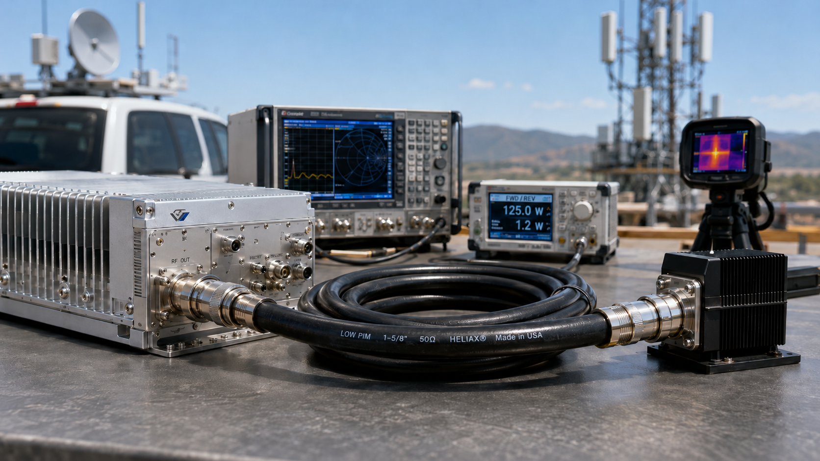
Feeder cable grade matters because it changes how much RF energy leaves the module, survives the cable path, and reaches the antenna. In a real C-UAS cabinet, vehicle jammer, or fixed perimeter system, a RF Power Amplifier can test well on a bench but look weak after installation if cable grade, connectors, and antenna loading are ignored. Here’s the deal: you are not only buying output watts. You are building a controlled RF chain where cable material, shielding, impedance accuracy, and heat behavior decide delivered power.
1. What Does Cable Grade Mean for RF Power Amplifier Output?
RF Power Amplifier feeder cable grade means the cable’s electrical and mechanical quality under real RF load. It covers conductor material, dielectric loss, shielding density, impedance tolerance, jacket stability, bend behavior, and connector compatibility. What’s the real story? Two cables can share one length and still create different antenna-end power because their grade differs.
What details define cable grade?
Cable grade starts with how well the cable preserves RF energy across frequency, temperature, movement, and installation stress. You might be wondering: which details matter most during procurement?
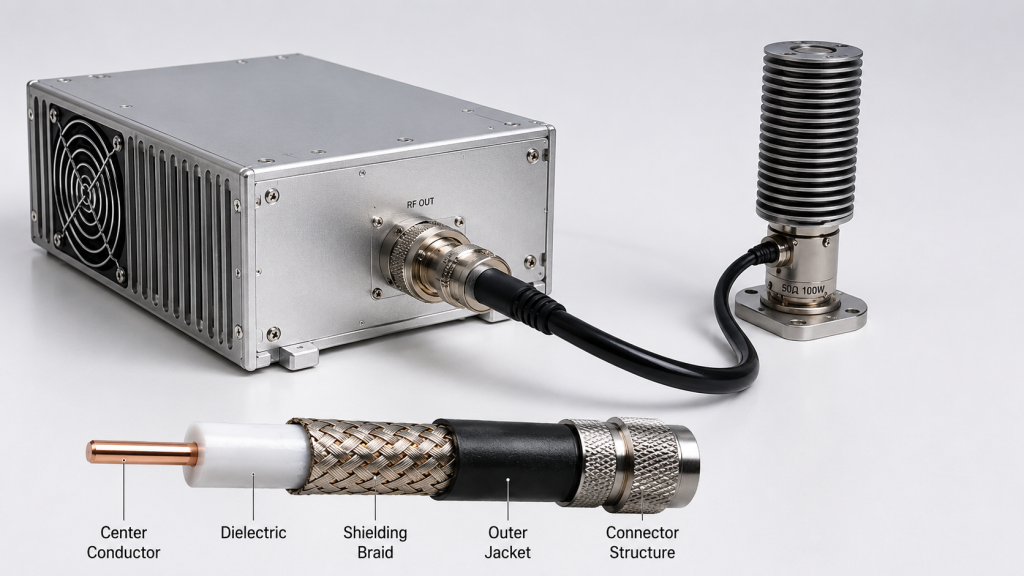
- Inner conductor material and plating quality
- Dielectric loss and temperature behavior
- Shielding braid or foil coverage
- 50-ohm impedance consistency
- Rated power and bend radius
- Connector type and assembly precision
Which cable traits affect output most?
Cable loss, impedance drift, and shielding leakage usually affect output before users notice physical damage. Here’s the kicker: a low-grade feeder may pass a short continuity check but still waste power at higher frequencies.
| Cable Trait | Practical Effect | User Risk |
|---|---|---|
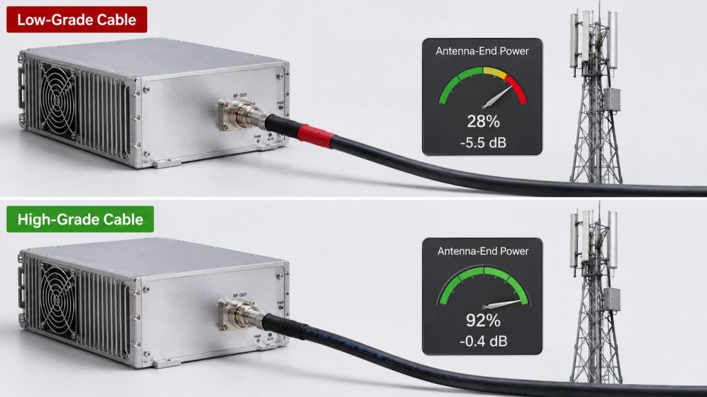
| High insertion loss | Less antenna-end power | Shorter coverage |
| Poor impedance control | More reflected power | VSWR alarms |
| Weak shielding | More leakage and coupling | Noise issues |
| Low heat stability | Changing RF behavior | Power drift |
Key Takeaway: Cable grade gives you a practical way to predict whether measured module power will survive real installation.
2. What Causes Cable Loss in RF Power Amplifier Systems?
RF Power Amplifier cable grade changes output by controlling how much transmitted power turns into delivered antenna power. A higher-grade feeder normally loses less energy across the same length, while a low-grade cable converts more RF energy into heat. This is where it gets practical: a module rated at 100W does not guarantee 100W at the antenna port.
Why does frequency make grade more visible?
Cable loss rises as frequency rises, so grade matters more in upper bands. Ready for the good part? The same cable that looks acceptable at 400MHz may create a painful drop at 2.4GHz or 5.8GHz.
- Lower frequency paths tolerate cable weakness better
- Higher frequency paths punish poor dielectric quality
- Long cable runs magnify grade differences
- High power makes heat loss more visible
What should you compare before blaming the module?
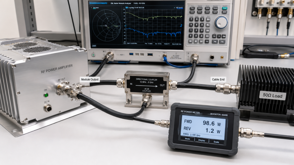
You should compare module-port power, cable-end power, and installed antenna behavior before judging an amplifier. Here’s a simple field rule: separate module performance from feeder loss before replacing hardware.
| Measurement Point | What It Shows | Why You Need It |
|---|---|---|
| Module output port | Baseline amplifier power | Confirms module health |
| Cable output end | Feeder loss | Shows cable grade effect |
| Antenna input | Installed delivery | Confirms field power |
| Reflected power | Load condition | Finds mismatch risk |
Key Takeaway: If you measure only at one point, you may blame a good module for a weak cable path.
3. What Makes RF Power Amplifier Cable Shielding Important?
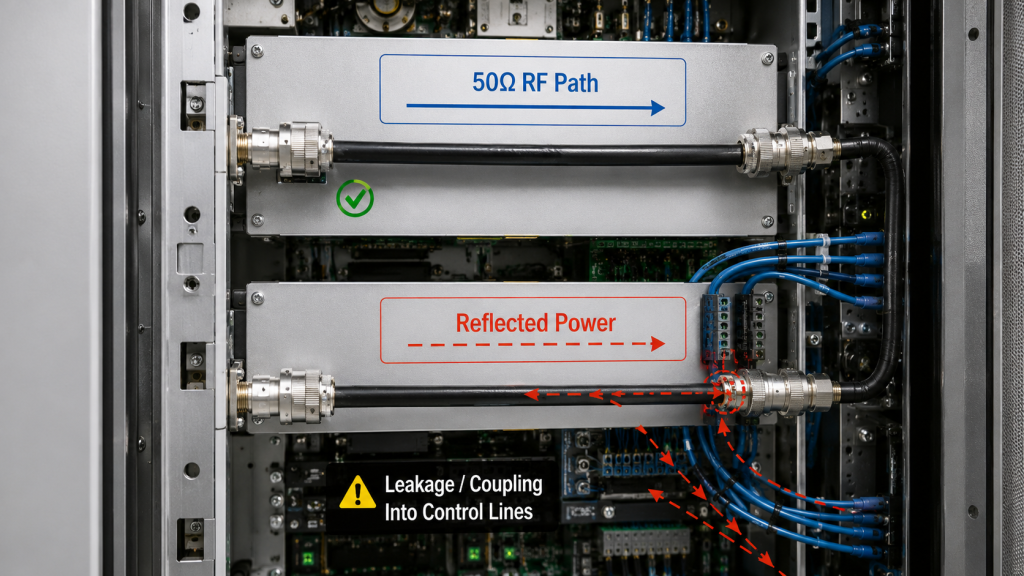
RF Power Amplifier impedance and shielding matter because they control reflected power, leakage, and RF path stability. A feeder cable should behave like a predictable 50-ohm transmission path, not a random part of the antenna system. But here’s the catch: poor shielding and loose impedance often show up only after full-power operation begins.
How does mismatch create false power problems?
Mismatch sends part of RF energy back toward the module instead of forward toward the antenna. You can see the problem: output power may look unstable while the root cause sits in cable or connector quality.
- Reflected power increases module stress
- VSWR protection may reduce output
- Coverage becomes inconsistent
- Field teams may misread alarms
- Long-duty operation becomes less predictable
How does shielding quality affect system behavior?
Shielding quality limits unwanted RF leakage, coupling, and interference inside dense cabinets or vehicle systems. Here’s the practical angle: shielding weakness can disturb nearby control cables, antennas, or measurement lines.
| Shielding Issue | Likely Symptom | Field Result |
|---|---|---|
| Loose braid coverage | RF leakage | Noisy cabinet behavior |
| Poor connector bonding | Unstable readings | Harder troubleshooting |
| Low shield density | Coupling into control lines | False alarms |
| Damaged jacket | Moisture and movement risk | Long-term drift |
Key Takeaway: Good impedance and shielding help your team separate real amplifier faults from cable-path faults.
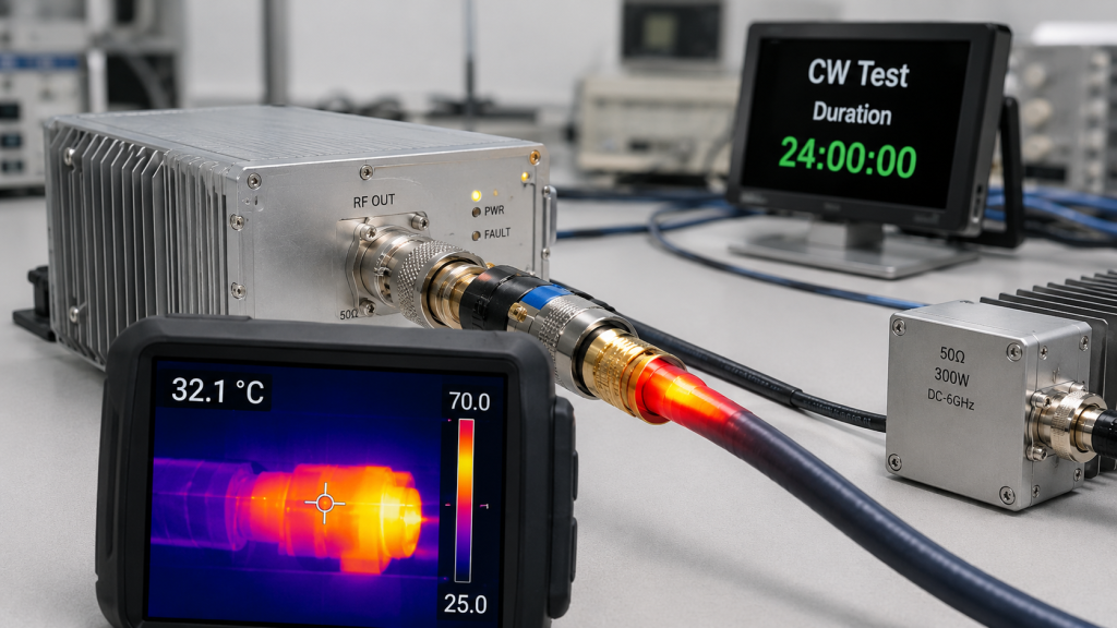
4. How Does RF Power Amplifier Cable Heat Affect Duty?
RF Power Amplifier cable heat affects duty cycle because lossy cables convert part of transmitted energy into thermal load. During long CW operation, cable temperature can change impedance, raise insertion loss, and increase reflected power. Here’s what many teams miss: cable heat can make a stable system drift after minutes or hours, not seconds.
Why does long-duty output expose weak cable grade?
Long-duty output keeps RF current flowing long enough for small losses to become visible heat. That’s the part worth watching: a cable that feels normal during a short test may warm up during real C-UAS operation.
- Jacket temperature rises
- Connector bodies warm near contact points
- Insertion loss can drift
- Reflected power can climb
- Protection logic may respond
What should engineers monitor during CW testing?
Engineers should monitor forward power, reflected power, cable temperature, and output stability during full-duty testing. No guesswork here: record behavior at low, middle, and high frequencies.
| Test Item | What It Reveals | Practical Action |
|---|---|---|
| Cable surface heat | Loss concentration | Upgrade cable grade |
| Connector heat | Assembly weakness | Re-terminate connector |
| Forward power drift | Delivery stability | Compare cable types |
| Reflected power | Load change | Check VSWR path |
Key Takeaway: Cable thermal behavior can decide whether a system stays stable during real continuous operation.
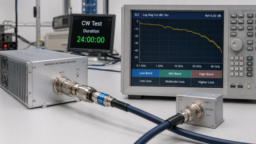
5. Why Are Wideband RF Power Amplifier Systems Sensitive?
RF Power Amplifier wideband systems are sensitive because cable loss changes across frequency. A feeder grade that performs well in one band may perform poorly at another band inside the same system. This is where it gets interesting: wideband modules make cable weakness easier to see because they test many frequency points, not one sweet spot.
Why does one cable behave differently by band?
Cable materials respond differently as frequency increases, especially through dielectric loss and conductor skin effect. So what happens next? Upper-band paths often show more loss even when cable length stays unchanged.
- 400MHz may show modest feeder loss
- 900MHz makes grade more noticeable
- 2.4GHz raises cable loss again
- 5.8GHz exposes weak dielectric quality
- Wideband testing reveals uneven delivery
How should wideband cable choices be reviewed?
Wideband cable selection should use swept data instead of one-frequency judgment. Here’s a useful approach: treat the cable as part of the RF architecture.
| Frequency Area | Cable Grade Concern | Review Method |
|---|---|---|
| Low band | Physical length and shielding | Insertion loss check |
| Mid band | Connector quality | Forward/reflected power |
| High band | Dielectric loss | Swept measurement |
| Full band | Power flatness | System-level report |
Key Takeaway: Wideband systems need cable grade decisions based on measured frequency behavior, not catalog claims alone.
6. How Do RF Power Amplifier Connectors Affect Cable Grade?
RF Power Amplifier connectors affect cable grade because even a good cable can perform poorly after weak termination. Connector plating, pin contact, crimp force, soldering quality, and strain relief all shape RF delivery. Here’s the part installers know well: many “bad cable” cases are really bad connector cases.
Why can a connector ruin a good cable?
A connector can ruin a cable when mechanical fit or electrical contact creates small discontinuities. Don’t skip this step: connector transitions can add loss and reflection even when cable grade looks correct.
- Poor crimping creates contact resistance
- Loose connectors shift impedance
- Wrong connector rating overheats
- Repeated bending stresses termination
- Moisture entry changes behavior
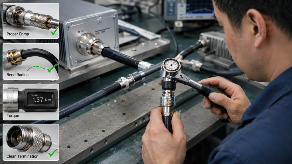
What assembly checks reduce connector risk?
Assembly checks should confirm connector torque, pull strength, continuity, insertion loss, and reflected power under load. Here’s a field-friendly checklist: verify before final cabinet closure.
| Assembly Factor | Failure Symptom | Check Method |
|---|---|---|
| Torque control | Loose contact | Torque wrench |
| Cable bend radius | Intermittent mismatch | Visual review |
| Connector rating | Heat at port | Full-power test |
| Weather sealing | Drift after exposure | Outdoor inspection |
Key Takeaway: Cable grade only works when connector grade and assembly quality match your RF power level.
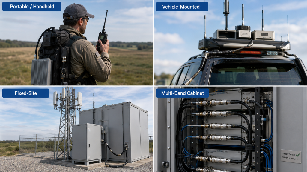
7. How to Choose Cable Grade for RF Power Amplifier Systems
RF Power Amplifier feeder cable should be chosen by frequency, length, power level, duty cycle, routing path, and installation environment. A portable system, vehicle-mounted jammer, and fixed tower do not need the same cable decision. Here’s the practical answer: choose for delivered power, not only purchase price.
What selection factors should come before price?
Selection should start with electrical loss and field reliability before cost comparison. You’ll save time later: cheap cable can create repeat visits, weak range, and confusing alarm behavior.
- Operating frequency range
- Cable length and routing complexity
- RF power level and CW duty
- Connector rating and availability
- Outdoor exposure and vibration
- Required test documentation
Which cable grade fits which system type?
Cable grade should match deployment format and mission runtime. Here’s a quick way to sort it: high frequency, long length, and high duty all push you toward better cable.
| System Type | Cable Priority | Suggested Focus |
|---|---|---|
| Handheld unit | Flexibility and weight | Short low-loss cable |
| Vehicle system | Vibration and heat | Rugged shielded cable |
| Fixed site | Low loss and weathering | High-grade outdoor feeder |
| Multi-band array | Frequency flatness | Swept cable data |
Key Takeaway: A cable spec should follow system reality, not a generic accessory list.
8. How to Measure Cable Loss in RF Power Amplifier Systems
RF Power Amplifier cable loss can be measured by comparing power at the amplifier output with power at the far end of the feeder. You can also use a VNA to measure insertion loss across frequency before full-power testing. Here’s the clean method: test cable behavior separately, then test it again inside the installed RF chain.
What tools help compare cable loss?
Engineers usually compare feeder loss with a power meter, calibrated load, VNA, spectrum analyzer, or directional coupler. Keep it simple: use repeatable measurement points before changing hardware.
- Power meter for delivered wattage
- VNA for insertion loss
- Directional coupler for forward/reflected power
- Dummy load for baseline testing
- Thermal camera for heat concentration
What measurement workflow works best?
A strong workflow starts with amplifier baseline output, then cable-only loss, then antenna-load behavior. Here’s the sequence: each step removes one unknown from the troubleshooting path.
| Step | Measurement | Purpose |
|---|---|---|
| 1 | Module into 50-ohm load | Baseline output |
| 2 | Cable insertion loss | Grade comparison |
| 3 | Cable plus connector heat | Assembly check |
| 4 | Antenna-end power | Delivered RF |
| 5 | Installed VSWR | Field behavior |
Key Takeaway: Measurement turns cable grade from opinion into usable engineering data.
9. How to Prevent RF Power Amplifier Output Loss from Cables
RF Power Amplifier mistakes from cable grade usually include blaming the module, oversizing power, ignoring connectors, and skipping antenna-end measurement. These errors waste time because the real loss sits between module and radiator. Here’s the warning sign: if bench power looks normal but field coverage feels weak, feeder grade deserves attention.
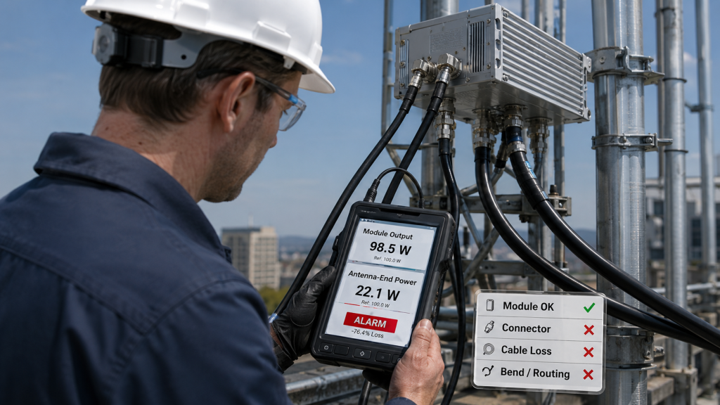
Why do teams misjudge amplifier output?
Teams misjudge output when they treat module wattage and antenna-end wattage as the same number. That shortcut gets expensive: long cable runs, high bands, and weak connectors can hide true delivery loss.
- Assuming all 50-ohm cables behave alike
- Testing only at module output
- Ignoring high-frequency loss
- Reusing old connectors
- Skipping thermal observation
Which mistakes cause the most rework?
The most costly mistakes happen after installation because access becomes harder. Here’s what to avoid: do not finalize wiring before cable grade, connector rating, and load behavior are tested.
| Mistake | Result | Better Action |
|---|---|---|
| Choosing by price only | Weak coverage | Compare loss data |
| No antenna-end test | Wrong diagnosis | Measure delivered power |
| Ignoring bend radius | Intermittent mismatch | Plan cable routing |
| Mixing connector grades | Heat and reflection | Match ratings |
Key Takeaway: Feeder cable grade prevents false failure analysis and keeps integration work focused.
10. How Can RF Power Amplifier Suppliers Reduce Cable Risk?
RF Power Amplifier suppliers reduce cable risk by providing measured module data, link-condition guidance, connector advice, and integration support. A useful supplier does not only ship a power block. Here’s what matters for you: supplier data should help your team predict installed performance before field acceptance.
What support should a supplier provide?
A supplier should help you connect module output, feeder conditions, antenna load, and protection logic. Ask for proof: useful guidance comes from test data, not vague claims.
- Full-band power sweep references
- VSWR and reflected-power notes
- Connector and cable compatibility advice
- Duty-cycle and thermal guidance
- Per-unit measurement records
- Integration support for field teams
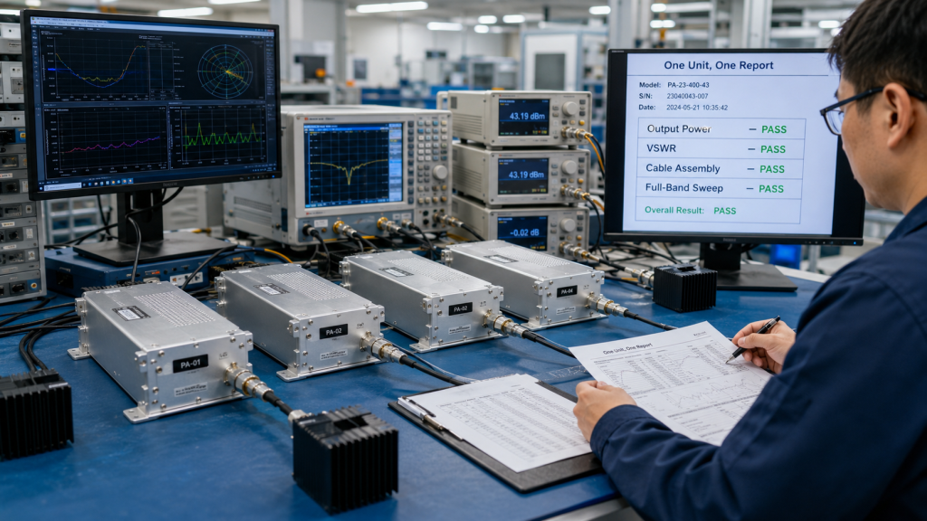
How does factory-side testing help your project?
Factory-side testing gives your team a baseline before installation variables appear. That’s the value of traceability: if a field issue appears, you can compare site data against known module behavior.
| Supplier Support | Project Benefit | Field Value |
|---|---|---|
| Unit test report | Baseline reference | Faster diagnosis |
| Cable guidance | Better feeder choice | Less power loss |
| VSWR advice | Safer RF path | Fewer alarms |
| Engineer support | Cleaner integration | Faster acceptance |
Key Takeaway: A source factory mindset helps you manage the full RF chain, not just the amplifier module.
Final Engineering Takeaway
Feeder cable grade affects insertion loss, reflected power, heating, wideband consistency, connector stability, and long-duty RF delivery. This article showed why a cable with the same length can still produce different antenna-end power, why high-frequency systems expose weak feeder choices, and how measurement protects you from blaming the wrong component. If you are building a vehicle-mounted, fixed-site, or multi-module C-UAS system, contact us today and discuss your RF chain with a factory team that builds modules, verifies output, and supports integration data.
Our brand position is simple: reliable RF defense begins where measured engineering replaces guesswork.
FAQ
Can I use a standard coax cable for a RF Power Amplifier system?
Yes, but only if its loss, power rating, impedance, shielding, and connector grade match your system. A standard cable may work in a short low-frequency setup, but high-frequency or long-duty systems need measured feeder performance.
How do I know if cable grade causes weak output?
You know by comparing module output power with antenna-end power. If module output stays stable on a 50-ohm load but antenna-end power drops, cable grade, connectors, or antenna loading should be checked.
What’s the best feeder cable grade for wideband RF systems?
The best grade is the one with low insertion loss, stable impedance, strong shielding, and proven behavior across your full frequency range. For wideband systems, swept data matters more than a single catalog number.
Can poor feeder cable trigger VSWR protection?
Yes, poor feeder cable can trigger VSWR protection when impedance drift, damaged connectors, or mismatch sends reflected power back toward the module. Protection behavior may look like amplifier weakness, but the cable path may be the cause.
How often should I recheck feeder cable performance?
You should recheck performance after installation, after cable movement, after connector replacement, and during scheduled maintenance. Outdoor, vehicle-mounted, and high-duty systems need more frequent checks because heat, vibration, and moisture change cable behavior over time.