


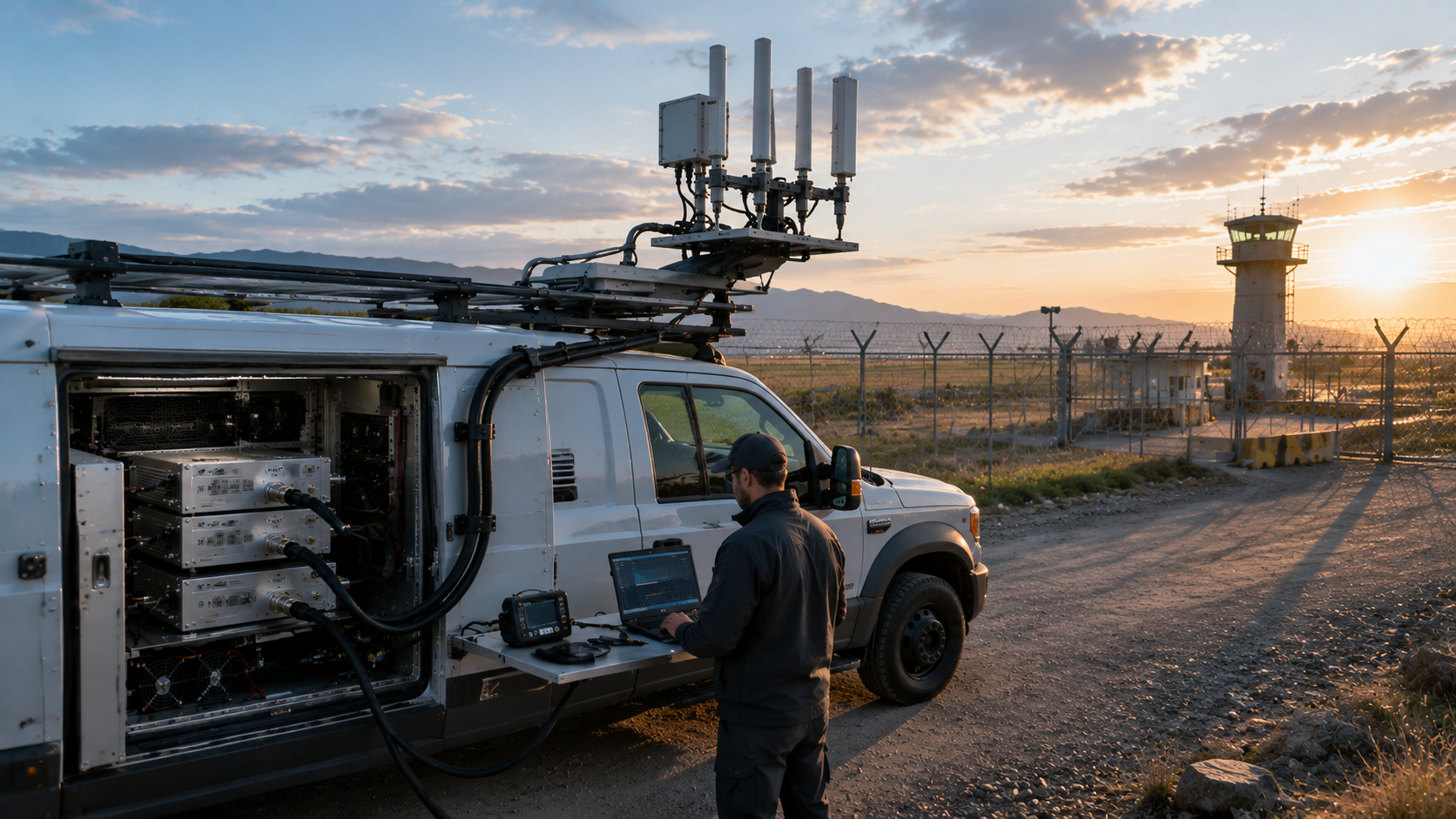
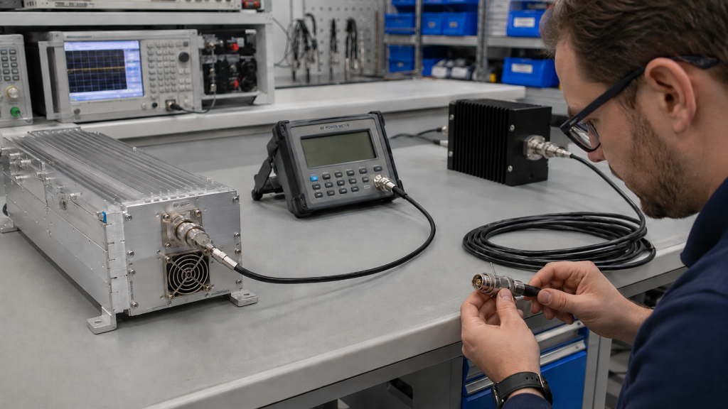
Checking RF Power Amplifier cable loss is one of the fastest ways to explain why a module looks weaker after installation. In a vehicle-mounted counter-UAS system, you may see a clean 100W reading near the amplifier output during factory testing, then measure lower power at the antenna end after several meters of feeder cable, connectors, bends, and cabinet routing. That gap does not always mean the amplifier is underpowered. It may simply mean part of the RF energy has already been lost inside the installed cable path.
Here’s the deal: both sides may be looking at different points in the same RF path. This article explains feeder cable length, connector loss, test position, antenna-end power, and field measurement accuracy, so you can judge whether the issue comes from the module or the installation path. For system integrators working with RF Power Amplifier modules, this distinction can prevent false rejection, unnecessary returns, and costly redesign work.
1. What Does Feeder Cable Length Mean in an RF Power Amplifier System?
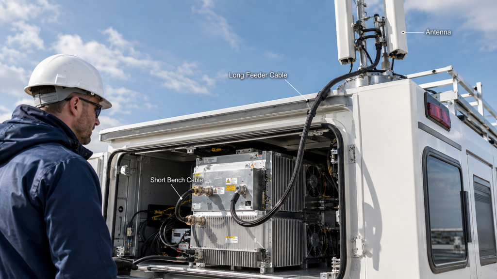
Feeder cable length means the physical RF path between the RF Power Amplifier output port and the antenna input. It is not just ordinary wiring, because every centimeter becomes part of the power delivery path. In many projects, engineers compare modules by frequency range, rated wattage, gain, and DC voltage, yet they leave cable length until mechanical layout begins. That order can create trouble when a cabinet, vehicle roof, mast, or protected enclosure forces a longer RF route than expected.
Does Cable Length Really Matter?
Cable length matters because RF energy must travel through a lossy conductor before radiation starts. Here’s the practical point: a feeder cable can look harmless in a drawing but still consume measurable RF power in real use.
● A short bench cable may hide installation loss
● A long roof-mounted feeder may reduce antenna-end power
● A tight cabinet path may add bends and adapter points
● A wideband system may suffer uneven loss across bands
For compact counter-UAS equipment, you may only need a short coaxial link from module to antenna. For vehicle-mounted or fixed-site systems, however, cable routing may pass through cabinets, sealed feedthroughs, brackets, and rooftop hardware.
What Should You Check Before Layout?
You should check cable length before final module placement, because RF layout affects power delivery. This is where it gets useful: a small mechanical decision can change your RF result.
● Distance from module bay to antenna base
● Cable type and rated frequency range
● Connector type on both sides
● Bend radius inside cabinet or mast
● Expected operating power and duty profile
| Layout Factor | What It Changes | User Impact |
|---|---|---|
| Short cable run | Lower path loss | More power reaches antenna |
| Long cable run | Higher insertion loss | Lower antenna-end reading |
| Tight routing | More stress and bending | Higher hidden risk |
| Early RF planning | Cleaner integration | Fewer late redesigns |
Key Takeaway: Treat feeder cable length as part of your RF design, not as a final mounting detail. This helps you avoid blaming a normal module for a layout-driven power drop.
2. How to Compare rf power amplifier Port Power and Antenna Power
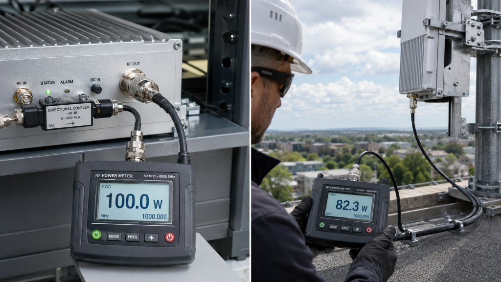
RF Power Amplifier port power and antenna power differ because RF energy passes through cables, connectors, adapters, and installation paths after leaving the module. Rated output usually refers to a defined test point near the amplifier output port under controlled conditions. Your field concern, however, usually sits at the antenna side or in actual coverage behavior. Those two numbers can differ even when the module works correctly.
Why Does Test Position Change the Number?
Test position changes the number because every component between meter and module affects the reading. What’s the real story? a low antenna-end value may include cable loss, connector loss, and adapter loss.
● Module output port reading shows amplifier behavior
● Cable-end reading shows delivery path behavior
● Antenna-end reading includes full installation loss
● Coverage behavior includes antenna pattern and site geometry
This is why our RF Power Amplifier delivery discussions usually include test position, cable length, load condition, and installation path, not only rated output power.
How Should You Compare Two Readings?
You should compare two readings only when measurement points and test conditions match. Here’s the catch: one wattage number without context can mislead both buyer and supplier.
● Record meter position
● Record cable length
● Record connector chain
● Record frequency point
● Record input drive and DC voltage
| Measurement Point | What It Mainly Shows | Common Misjudgment |
|---|---|---|
| Module output port | Amplifier output capability | Seen as the only useful number |
| Feeder cable end | Cable delivery efficiency | Mistaken for module weakness |
| Antenna input | Installed RF path result | Used without loss correction |
| Field coverage | Full system behavior | Blamed on wattage alone |
Key Takeaway: Module port power and antenna-end power are not the same result. You need both numbers before judging whether output has really fallen.
3. What Causes rf power amplifier Output Drops After Installation?
Cable loss increases in an RF Power Amplifier system because longer feeder cables create more insertion loss before energy reaches the antenna. The amplifier can still deliver rated power at its output port, yet the antenna may receive less power after the RF path absorbs part of that energy. This difference often appears during field acceptance, especially when engineers test at the antenna end without subtracting cable loss.
What Does Insertion Loss Mean Here?
Insertion loss means RF power lost when a cable or component sits inside the signal path. Here’s a simple way to see it: the cable does not lower the module’s rated port output, but it can lower delivered antenna power.
● Longer cable creates more loss
● Lower-quality cable creates more loss
● Higher frequency often creates more loss
● Extra adapters add more loss
● Heat and mechanical stress can worsen performance
For example, a short bench cable may produce a reading close to module output. A longer installed cable may show a lower value even when the module stays stable.
Why Does This Create False Blame?
It creates false blame because engineers may assign all loss to the RF Power Amplifier instead of the full RF path. This is the part that saves time: before starting a return request, split module behavior from cable behavior.
● Test near the module
● Test after the cable
● Compare both readings at the same frequency
● Check connector temperature and fit
● Use a known good cable as reference
| Cable Situation | Likely Result | Better Judgment |
|---|---|---|
| Short low-loss cable | Small power difference | Module reading close to antenna reading |
| Long standard cable | Larger power difference | Cable correction needed |
| Old or stressed cable | Unstable readings | Replace or retest cable |
| Multiple adapters | Hidden extra loss | Simplify RF path |
Key Takeaway: A lower antenna-end reading does not automatically prove weak amplifier output. It may simply show power already spent inside the feeder path.
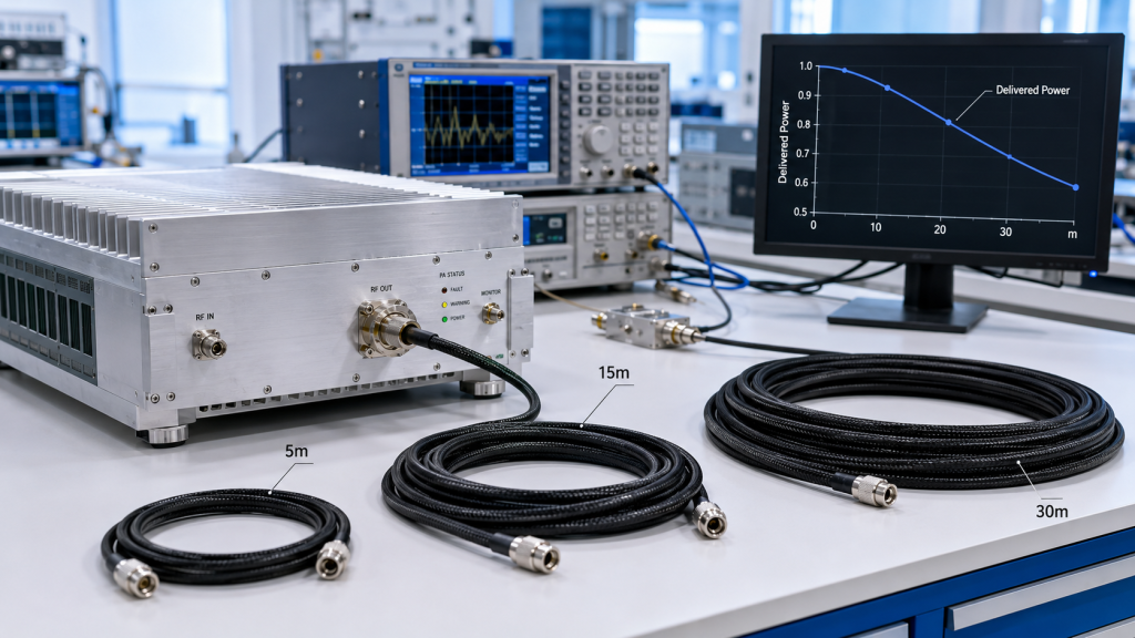
4. How to Choose rf power amplifier Cable Length for High-Frequency Bands
Frequency makes RF Power Amplifier cable loss worse because feeder cable attenuation usually rises as operating frequency increases. A cable length that looks acceptable at 400MHz may cause much more visible loss at 2.4GHz or 5.8GHz. This matters in multi-band counter-UAS systems where low-band channels may look healthy while high-band channels appear weaker after installation.
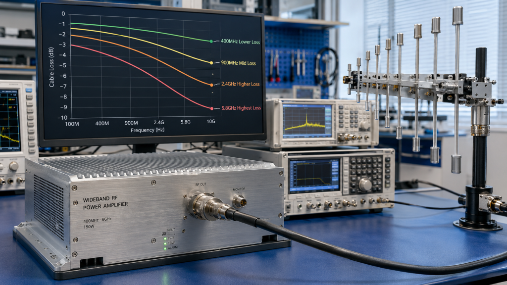
Why Are High Bands More Sensitive?
High bands are more sensitive because RF energy faces greater transmission loss through many cable structures. You might be wondering: why does the same cable behave differently across bands? Frequency changes current distribution, dielectric behavior, and practical loss inside the cable.
● 400MHz paths often tolerate longer cable better
● 900MHz loss may remain manageable with good cable
● 2.4GHz loss becomes more noticeable
● 5.8GHz loss can quickly affect antenna-end power
For wideband RF Power Amplifier systems, this makes band-by-band verification more useful than one comfortable center-frequency test.
What Happens in C-UAS Systems?
C-UAS systems may cover low, mid, and high RF bands at once, so cable behavior can vary across channels. Here’s where misjudgment starts: one installation may look strong at one band and weak at another.
● Low-band module output may match field expectations
● High-band output may look reduced at antenna side
● Long roof cables can exaggerate high-band loss
● Antenna placement may force longer high-frequency routes
| Frequency Zone | Cable Sensitivity | Field Risk |
|---|---|---|
| Low band | Lower sensitivity | Less visible loss |
| Mid band | Moderate sensitivity | Needs cable review |
| High band | Higher sensitivity | Antenna-end power drop |
| Wideband system | Uneven sensitivity | Band-specific misreading |
Key Takeaway: The higher the frequency, the more cable length matters. This helps you avoid judging all bands by one low-frequency result.
5. What Connector Issues Affect rf power amplifier Power Delivery?
Connectors add RF Power Amplifier installation loss because every mating point introduces contact resistance, mismatch risk, and mechanical uncertainty. Cable length may be the obvious factor, but real installations rarely use one perfect cable from module to antenna. You may have N-type connectors, SMA adapters, feedthroughs, bulkhead points, angled adapters, waterproof joints, or rooftop transitions. Each detail can reduce delivered power or create unstable readings.
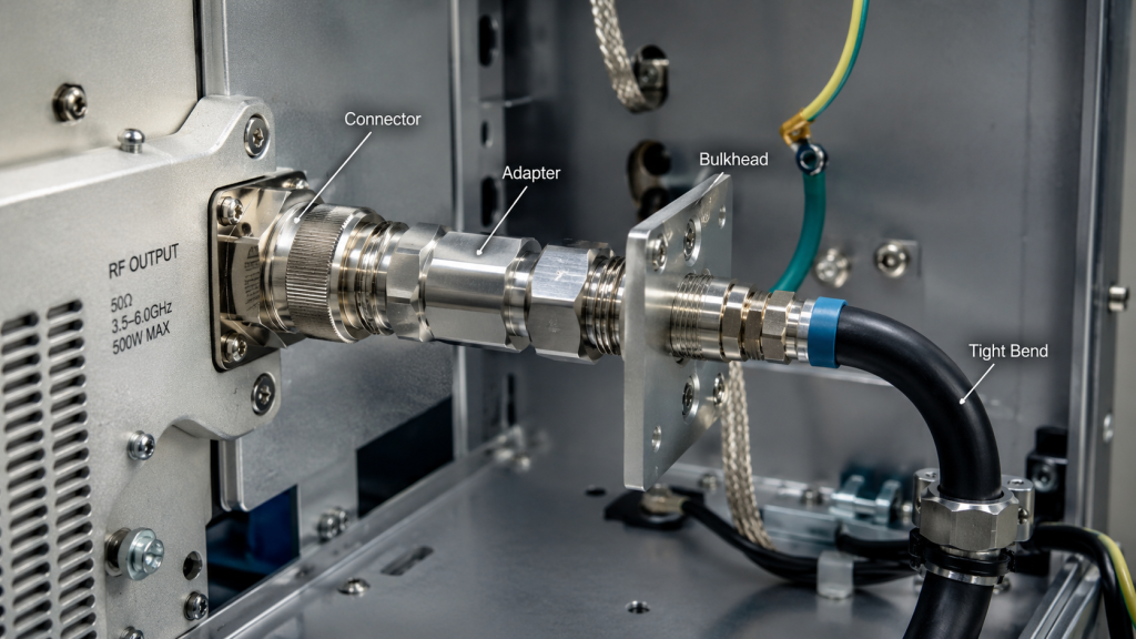
Which Details Are Easy to Miss?
Small connection details are easy to miss because they look mechanical rather than electrical. Here’s the quiet problem: a connector that looks tight may still add loss or reflection.
● Loose connector threads
● Mixed connector standards
● Adapter stacks
● Oxidized outdoor joints
● Sharp cable bends
● Vibration at vehicle mounting points
This is why engineering communication should include interface direction, connector choice, mounting space, and cable route, not only “frequency and wattage.”
How Do You Reduce Hidden Loss?
You reduce hidden loss by simplifying the RF path and controlling each connection point. Ready for the practical list? fewer transitions usually mean fewer unknowns.
● Use proper connector type for power and frequency
● Avoid unnecessary adapter chains
● Keep bend radius within cable limits
● Inspect outdoor sealing and corrosion risk
● Recheck torque after vibration exposure
| Hidden Factor | Possible Effect | Practical Action |
|---|---|---|
| Adapter chain | Added loss | Use direct cable ends |
| Loose connector | Fluctuating power | Retighten and retest |
| Sharp bend | Cable damage | Reroute path |
| Outdoor corrosion | Rising loss | Seal and inspect |
Key Takeaway: Cable loss is not only about length. Connectors, adapters, bends, and routing can all change final RF delivery.
6. Why Can Long Cables Make an RF Power Amplifier Look Unstable?
Long cables can make an RF Power Amplifier look unstable because cable-related problems may appear as power drift, reflected power, alarm events, or inconsistent test data. The module may operate normally at its port, while the installed cable path creates changing load conditions. If the feeder cable quality is poor, the connector is loose, or the antenna match is poor, the system may trigger protection behavior that looks like amplifier instability.
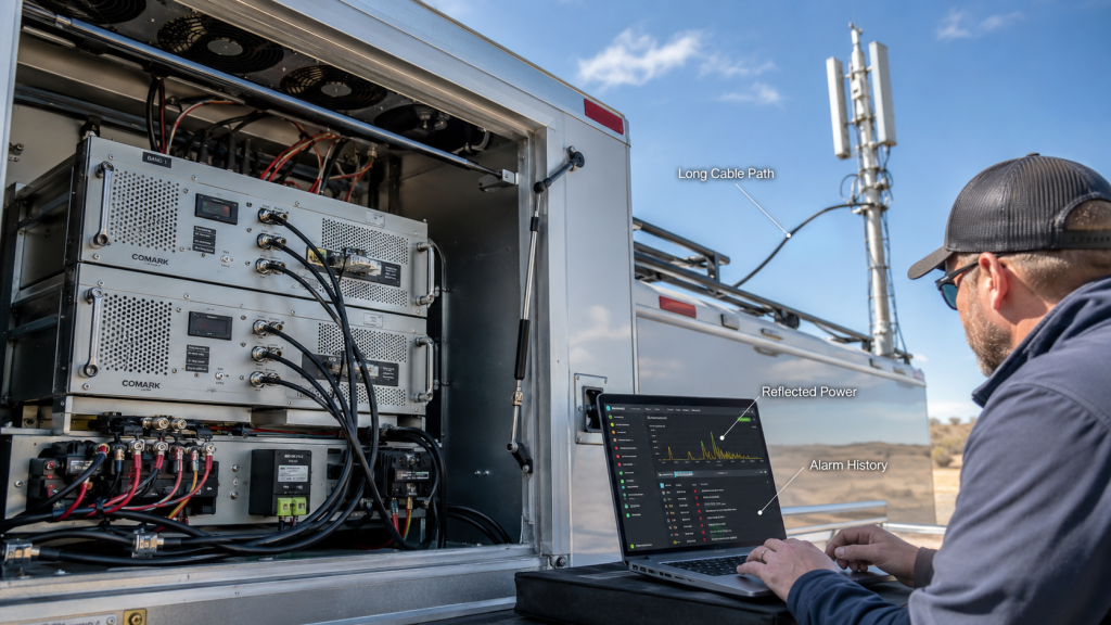
What Symptoms Can Cable Problems Create?
Cable problems can create symptoms that feel like module faults. Here’s the tricky part: the same amplifier may look stable with a dummy load and unstable after installation.
● Lower antenna-end power
● Reflected power increase
● Random alarm events
● Output fluctuation during vibration
● Connector heating
● Inconsistent readings between test days
High-power RF Power Amplifier modules should include VSWR, temperature, and voltage protection logic because field issues can grow into real output-stage risk.
How Do Protection Alarms Fit In?
Protection alarms fit in as safety responses, not automatic proof of a weak module. This is where careful testing matters: an alarm may point toward cable, load, or installation stress.
● Check load condition before replacing module
● Inspect cable path during alarm events
● Compare dummy-load behavior against antenna behavior
● Review reflected power and temperature together
● Confirm whether alarm repeats at same frequency
| Symptom | Possible Cable Cause | Next Check |
|---|---|---|
| Power fluctuation | Loose connector | Retighten and retest |
| High reflected power | Mismatch or cable fault | Test with dummy load |
| Hot connector | Loss or poor contact | Replace connector |
| Alarm trigger | Load-path stress | Review VSWR data |
Key Takeaway: A cable-related RF path problem can look like amplifier instability. Check test position and load condition before judging the module.
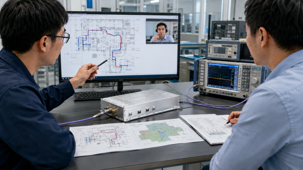
7. What Test Conditions Make rf power amplifier Factory and Field Results Different?
RF Power Amplifier factory and field tests disagree because they often use different cables, loads, measurement points, instruments, and environments. A factory test bench may use short calibrated cables, a stable DC supply, a known dummy load, and controlled ambient conditions. Field testing may involve long feeder cables, installed antennas, cabinet routing, outdoor temperature, vehicle vibration, and different measurement technique.
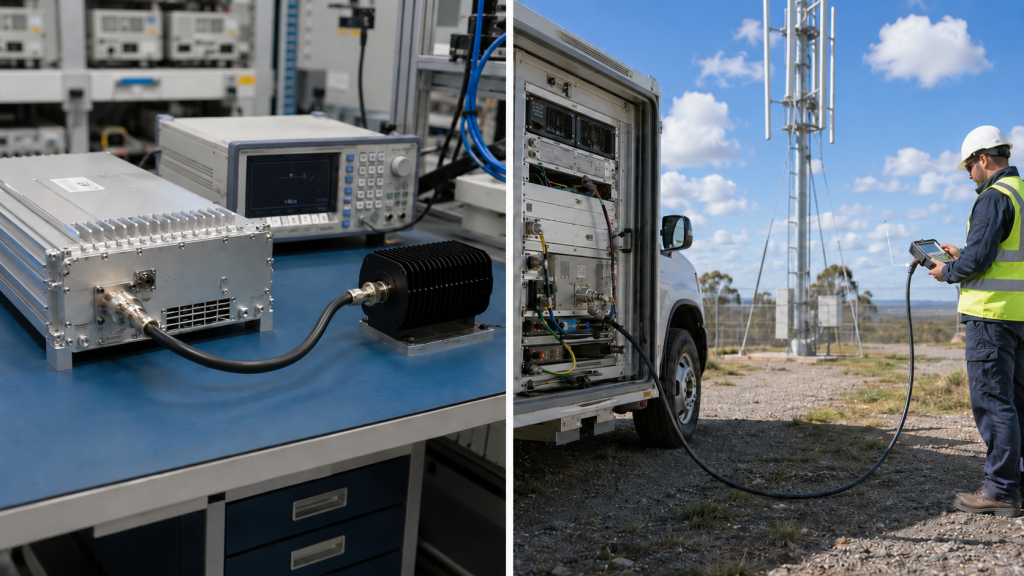
What Does a Factory Test Usually Control?
A factory test usually controls the RF path so module behavior can be measured clearly. What’s the real story? factory data may be accurate but still not equal to your installed antenna-end value.
● Short cable path
● Calibrated instrument setup
● Known dummy load
● Stable DC input
● Defined frequency point
● Controlled operating condition
For factory-direct RF modules, clear test conditions and unit-level reports help customers compare factory data with their own field measurements more fairly.
What Should Field Teams Record?
Field teams should record every condition that changes the RF path. This is the difference-maker: a clear field record turns dispute into diagnosis.
● Cable length and cable model
● Connector and adapter list
● Measurement position
● Antenna model and placement
● DC voltage during test
● Ambient temperature
● Frequency and input drive
| Test Condition | Factory Setup | Field Setup |
|---|---|---|
| Cable length | Short and known | Often longer |
| Load | Dummy load | Real antenna |
| Environment | Controlled | Variable |
| Measurement point | Module-side | Often antenna-side |
Key Takeaway: Factory and field numbers can only be compared fairly when RF path and measurement position are clear. Otherwise, both numbers may be correct but not comparable.
8. How to Measure rf power amplifier Cable Loss Before Field Acceptance
You can check RF Power Amplifier cable loss by comparing power readings before and after the feeder cable under the same frequency, input drive, DC voltage, and load condition. Do not judge the module only from antenna-end power. A better method is to split the system into segments, test each segment, and find where power drops appear.
What Test Sequence Works Best?
A step-by-step sequence works best because it separates module output from path loss. Here’s the useful order: start close to the amplifier, then move downstream.
● Test near module output with proper load
● Test after short reference cable
● Test after installed feeder cable
● Compare low, middle, and high frequency points
● Inspect connectors for heat or looseness
● Log DC voltage and input drive
This approach helps system integrators reduce unnecessary returns, avoid wrong blame, and shorten field commissioning.
What Data Should You Keep?
You should keep data that proves where the loss appears. Here’s the field habit that pays off: write down conditions before changing hardware.
● Frequency
● Input power
● DC voltage
● Cable length
● Connector chain
● Measurement point
● Load type
● Ambient condition
| Check Step | Purpose | Result Meaning |
|---|---|---|
| Module-side test | Verify amplifier output | Confirms port behavior |
| Short cable test | Create reference | Shows expected baseline |
| Long cable test | Measure path loss | Finds delivery drop |
| Connector check | Locate hidden issue | Finds contact fault |
Key Takeaway: Before blaming the RF Power Amplifier, compare readings before and after the feeder cable. That simple split often reveals the real cause.
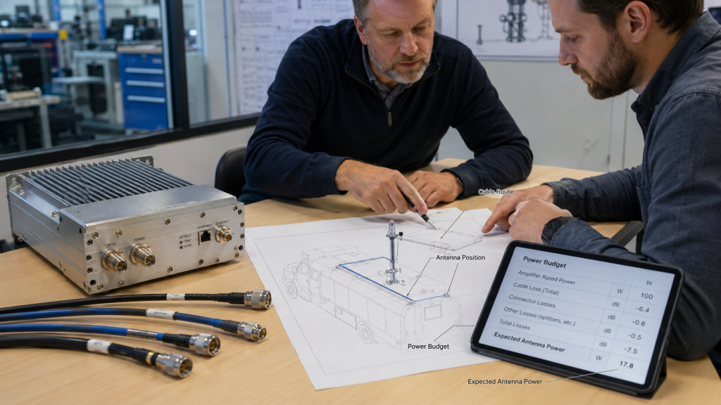
9. How Should Cable Length Affect RF Power Amplifier Selection?
RF Power Amplifier selection should include cable length because the system needs delivered antenna power, not only rated module power. Asking for 50W, 100W, or 200W without reviewing feeder path can produce an oversized or poorly arranged system. Sometimes the smarter move is shorter cable, better cable grade, closer antenna placement, or cleaner routing rather than a higher wattage module.
When Should You Avoid Oversizing?
You should avoid oversizing when cable layout can solve the delivery problem more efficiently. Here’s the cost angle: using higher wattage to compensate for avoidable cable loss can raise heat, DC current, and system price.
● Long cable caused by poor module placement
● High-band antenna placed too far away
● Standard cable used at demanding frequency
● Too many adapters in cabinet path
● Weak cable grade chosen for strong power
For wideband systems, amplifier, antenna, feeder cable, power supply, and thermal design should be reviewed together.
What Selection Questions Help?
Good selection questions link module power with installation reality. You might be wondering: what should you ask before purchase?
● Where will the module sit?
● Where will the antenna sit?
● Which cable model will connect them?
● What frequency bands matter most?
● What antenna-end power does the system need?
● What duty cycle and temperature apply?
| Selection Factor | Why It Matters | Better Decision |
|---|---|---|
| Cable length | Changes delivered power | Plan RF route early |
| Frequency | Changes loss severity | Review high bands closely |
| Antenna placement | Changes cable need | Reduce path length |
| Module wattage | Affects heat and DC load | Avoid blind oversizing |
Key Takeaway: Feeder cable length should be part of amplifier selection, not an afterthought. That keeps you from solving a routing problem with unnecessary wattage.
10. How Can Suppliers Prevent RF Power Amplifier Cable-Loss Misjudgment?
A supplier can prevent RF Power Amplifier cable-loss misjudgment by helping customers understand the full RF path, not only the rated output number. A mature supplier should explain where power is measured, how cable length affects antenna-end power, what connector chain should be avoided, and how field teams should retest when results look low.
What Should a Supplier Clarify Early?
A supplier should clarify test conditions before installation begins. Here’s the professional difference: good support reduces guesswork before hardware reaches the site.
● Rated output test point
● Recommended cable type
● Acceptable connector chain
● Load and antenna assumptions
● High-band loss risk
● Protection alarm meaning
● Retest method after installation
As a source factory, RF SKYPOWER can discuss module design, interface definition, protection logic, test records, and engineering support in one communication loop.
Why Does This Matter for C-UAS Projects?
It matters because C-UAS projects often combine multiple bands, antennas, cables, power channels, and mounting conditions. This is where experience beats a larger wattage claim: vehicle-mounted, fixed-site, and multi-band systems need power delivery planning.
● Vehicle vibration changes connector reliability
● Fixed masts may force long feeder paths
● High-band antennas need cable-loss review
● Multi-module systems need consistent test rules
● Acceptance teams need fair comparison data
| Supplier Support Area | What It Prevents | User Benefit |
|---|---|---|
| Test condition clarity | Port versus antenna confusion | Fair comparison |
| Cable path review | Hidden loss | Better field result |
| Protection explanation | Wrong fault blame | Faster diagnosis |
| Unit-level records | Data disputes | Cleaner acceptance |
Key Takeaway: A good supplier helps you understand the whole RF path, not only the amplifier port rating. That support can save more field time than simply pushing a bigger module.
Final Engineering Takeaway
Feeder cable length can make a healthy RF Power Amplifier look underpowered because antenna-end power includes cable loss, connector loss, routing details, frequency sensitivity, and field measurement conditions. This article solved one common engineering dispute: the module may pass factory testing, while the installed system still shows lower delivered power because the RF path changed.
If you need RF modules for vehicle-mounted, fixed-site, or multi-band C-UAS systems, we can help you review module output, feeder cable path, connector selection, antenna placement, protection behavior, and test conditions before false conclusions slow your project. At RF SKYPOWER, our position is simple: mission-critical RF systems should be judged by engineered power delivery, not by isolated wattage claims. Contact us today to discuss your required frequency range, power level, antenna layout, and installation environment with our engineering team.
FAQ
Can I judge an RF Power Amplifier by antenna-end power only?
No, you should not judge it by antenna-end power only. Antenna-end power includes feeder cable loss, connector loss, adapter loss, antenna match, and installation conditions, so it may not represent the module’s actual output port performance.
What’s the best way to check if cable loss causes low output?
The best way is to compare power near the amplifier output and after the feeder cable. Use the same frequency, input power, DC voltage, load condition, and instrument setup so the difference shows cable-path loss more clearly.
How do I know if my feeder cable is too long?
You know the cable may be too long when antenna-end power drops more than expected, especially at higher frequencies. Check cable type, frequency rating, length, connector chain, and measured loss before increasing amplifier wattage.
Can I solve cable loss by choosing a higher-power amplifier?
Yes, sometimes, but it should not be your first move. A higher-power amplifier may add heat, current demand, cost, and protection stress, while shorter cable, better cable grade, or improved antenna placement may solve the issue more cleanly.
What’s the best supplier question before installation?
The best question is: “Where is rated output measured, and how should I account for feeder cable loss in my system?” This helps you compare factory data and field data fairly before blaming the amplifier or redesigning the system.