











C-UAS wideband RF PA performance should be verified at the project-critical frequency points under measurement and operating conditions that materially affect the project decision—not from the listed frequency span alone.
A broad frequency label establishes where a module is intended to operate. It does not by itself show what RF performance is available at the frequencies the project actually uses, whether the measurements are comparable, or what decision the available evidence can support.
The practical question is:
Does the available evidence show acceptable performance at the required project frequency points under conditions that support the intended decision?
The required frequency set should already come from the RFQ, system requirement, or applicable frequency-range qualification. This page focuses on how to review condition-matched evidence at those defined points and decide whether the wideband performance requirement is adequately supported.
1. What C-UAS Wideband RF PA Performance Must Prove
The wideband performance requirement should not be treated as satisfied simply because the stated operating range includes the project frequencies.
The evidence should show whether the amplifier satisfies the performance requirements assigned to the defined operating points.

Depending on the project, that may include:
- required RF output;
- gain or allowed gain variation;
- the Actual Pin condition used to obtain the result;
- the Pout reference plane;
- DC behavior where relevant;
- hot-state evidence where thermal state affects the decision;
- load or reflected-power behavior where required;
- and the evidence scope supporting the result.
Three questions should remain separate:
- Does the module cover the required frequency set?
- Does it deliver the required RF performance at those points?
- Where required, does that performance remain acceptable under the defined operating condition?
The first question establishes frequency eligibility.
The second establishes usable RF performance.
The third establishes whether the result remains valid under the operating boundary relevant to the project.
For this page, the first question is treated as an input.
The main task is to review the evidence supporting the second and third questions.
C-UAS Wideband Performance Evidence Map
| Project Point | Requirement / Limit | Evidence to Review | Actual Pin / Reference Plane | Operating Condition | Evidence Scope | Decision Use |
|---|---|---|---|---|---|---|
| Required frequency A | Project-defined | RF result at the required point | Defined | Defined where material | Qualification / sample / unit as approved | Wideband performance review |
| Required frequency B | Project-defined | RF result at the required point | Defined | Defined where material | Qualification / sample / unit as approved | Wideband performance review |
| Required frequency C | Project-defined | RF result at the required point | Defined | Defined where material | Qualification / sample / unit as approved | Wideband performance review |
| Additional critical point | Project-defined | Project-specific RF evidence | Defined | Project-specific | Approved scope | Engineering review |
The exact frequencies and limits should come from the applicable project requirement.
This table does not create universal acceptance limits.
Its purpose is to connect:
required point → required result → evidence → test boundary → evidence scope → decision use
2. Lock the Test Boundary for the Required Frequency Set
Once the project frequency set is already defined, establish the measurement boundary that makes results at those points interpretable and comparable.
This page does not repeat RF amplifier frequency range selection; it assumes the project frequency set has already been defined.
It assumes that decision has already been made through the RFQ, system requirement, or applicable frequency-range qualification.
The review should now focus on the conditions capable of materially changing the RF result.
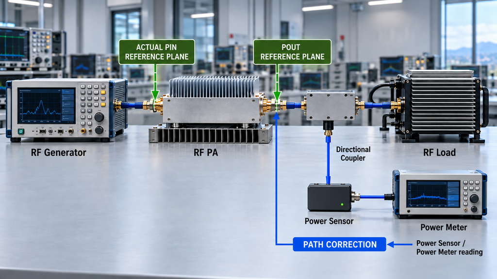
Actual Pin
Do not rely only on the signal-generator setting.
The RF amplifier input drive level should be defined as an Actual Pin condition at the applicable PA input reference plane.
If the project uses a fixed input-power rule, apply that rule consistently.
If controlled adjustment of Pin is allowed to reach another defined operating state, document that rule.
The reviewer should be able to determine how the amplifier was driven at each required frequency point.
A difference in output should not be interpreted as frequency-dependent PA behavior until the input condition is understood.
Pout Reference Plane
Output power also needs a defined physical boundary.
A value reported at the PA output port is not automatically equivalent to:
- output after a cable;
- output after a filter;
- output after a combiner;
- or power measured farther downstream.
Any correction applied between the instrument reading and reported Pout should remain traceable to the defined reference plane.
Without that boundary, apparently similar output values may not be directly comparable.
Signal and Operating Condition
The relevant RF operating condition should also be defined where it changes the decision.
That may include:
- CW;
- pulsed operation;
- a defined modulation;
- frequency hopping;
- another approved waveform;
- duty cycle;
- or test duration.
Load, DC condition, cooling, and thermal state should also be recorded where they materially affect the result.
Evidence Scope
The evidence identity should match the decision being made.
Depending on the approved plan, the evidence may come from:
- qualification testing;
- a representative sample;
- batch-level evidence;
- individual-unit shipment evidence;
- or another controlled scope.
An individual S/N-linked report may be required for unit-level shipment acceptance.
It should not be treated as a universal requirement for every wideband performance review.
Likewise, qualification or sample evidence should not automatically be presented as individual-unit proof.
3. Compare RF Evidence at the Required Frequency Points
Once the required points and test boundary are defined, compare the RF evidence used to support the wideband performance decision.
The purpose is not to reproduce a full swept-frequency test procedure or a complete gain-flatness calculation.
The purpose is to determine whether the available specialist evidence supports the project requirement at each required point.
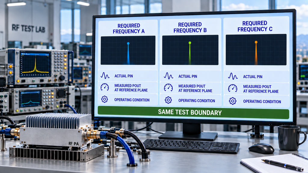
For each point, the reviewer should be able to identify:
- frequency;
- applicable RF requirement;
- Actual Pin rule;
- measured Pout at the defined reference plane;
- gain or gain variation where required;
- applicable Vdc and Idc where relevant;
- load condition;
- thermal state where relevant;
- applicable limit or engineering-review boundary;
- and evidence scope.
A center-frequency measurement cannot establish performance at other required frequencies.
Likewise, a full-band curve is useful only when its test condition, measurement boundary, and relationship to the project requirement are understood.
Review Frequency-Dependent Behavior
Wideband amplifiers do not need to produce identical numerical results at every frequency unless the project explicitly requires that.
What matters is whether the measured behavior remains acceptable for the defined use.
Depending on the design and operating condition, the evidence may show:
- lower or higher Pout at different points;
- different input-drive requirements;
- gain variation;
- different DC current;
- different thermal behavior;
- or another frequency-dependent characteristic.
A visible difference is not automatically a failure.
It becomes an approval issue when it violates the applicable requirement or creates an unresolved engineering concern for the intended operating condition.
Use Specialist Test Results Without Rebuilding Their Methods
If the project requires an RF power amplifier swept test at the approved full-power condition, that measurement should be produced by the applicable specialist procedure.
If RF power amplifier gain flatness is itself an acceptance requirement, the specialist procedure should establish the comparable gain evidence.
This page should consume those results rather than recreate their complete test methods.
The intended flow is:
specialist measurement → condition-matched evidence → wideband performance review
When the Evidence Is Not Comparable
If two required-point results were obtained under materially different conditions, do not force a direct comparison.
First review:
- Actual Pin;
- waveform;
- Pout reference plane;
- path correction;
- Vdc;
- load;
- duty cycle;
- thermal state;
- configuration;
- and measurement method.
If a material difference cannot be reconciled, repeat the necessary measurement under an approved boundary.
A missing comparison is an evidence problem.
It should not be converted into an unsupported PASS or FAIL conclusion.
4. Check Hot-State Evidence Where It Affects Approval
Thermal and DC behavior matter to this page only when they materially change the RF evidence used for the wideband performance decision.
The question is not how to design the complete thermal solution.
It is:
Does thermal state change the result being used to approve a required frequency point?
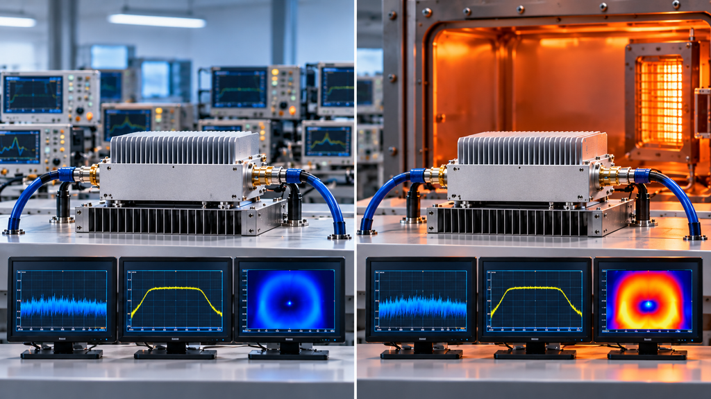
Where hot-state evidence is required, the record may need to identify:
- frequency;
- RF operating condition;
- Actual Pin rule;
- Vdc;
- Idc;
- cooling condition;
- defined thermal state;
- applicable temperature measurement;
- and RF output after the required state is reached.
A higher DC current at the same supply voltage increases DC input power.
If RF output does not increase proportionally, dissipation may also increase depending on efficiency and operating state.
The review should therefore compare RF and electrical behavior under the defined operating boundary rather than treating current alone as a direct heat measurement.
Cold and Hot Results Answer Different Questions
A cold-state result can be valid for that state.
It does not automatically prove stabilized hot-state performance.
Likewise, a hot-state result should not be compared with a cold result as if thermal state were irrelevant.
Where hot-state approval matters, make the thermal state explicit and compare evidence obtained under a defined boundary.
If heatsink selection, airflow, thermal resistance, enclosure design, or cooling architecture becomes the main question, that work belongs in RF power amplifier thermal management rather than this wideband performance review.
5. Separate PA-Module Evidence from Installed RF-Path Evidence
The PA module and the installed RF path should not be treated as the same test object.
A controlled PA-port test answers questions about the amplifier under the defined load and measurement boundary.
Once the amplifier is connected to the installed RF path, additional elements may affect the result, including:
- feeder loss;
- cables;
- connectors;
- adapters;
- filters;
- combiners;
- switches;
- antennas;
- and frequency-dependent mismatch.
These effects can change with frequency.
An installed-path result may therefore differ from the PA-port baseline even when the PA itself has not changed.

PA-Port Evidence
PA-port evidence can establish whether the amplifier meets its defined module-level requirement under the approved test condition.
The Pout reference plane and applicable path correction should remain clear.
Installed-Path Evidence
Installed-path evidence evaluates what happens after additional RF-chain elements are introduced.
It may include:
- insertion loss;
- forward and reflected power;
- VSWR or return-related behavior;
- frequency-specific path response;
- or system-level delivered power where that is the defined objective.
A reduced downstream result should not automatically be attributed to the PA.
Likewise, a good PA-port result should not automatically be presented as proof that the installed RF path is acceptable.
The two evidence types answer different questions:
PA-port evidence → module performance
Installed-path evidence → RF-chain or system-path behavior
Both may matter to integration, but they should remain separately attributable.
When Control or Protection Changes the RF Result
Control or protection evidence belongs in this review only when it changes the interpretation of a required frequency-point result.
For example, an alarm, protection-active state, shutdown, foldback response, or recovery event may need to be recorded if it occurred during the applicable test condition.
The wideband performance review should only determine whether that state materially affected the RF evidence.
Detailed control-interface mapping, alarm logic, thresholds, reset behavior, and protection-state-machine verification belong in their respective specialist procedures.
6. Close the Wideband Performance Evidence Review
The review should finish by determining whether the evidence adequately supports the wideband performance requirement—not whether every other shipment or system requirement is complete.
A decision-ready review should connect each required point to:
- the applicable requirement;
- the RF evidence;
- the measurement boundary;
- the operating condition;
- the evidence scope;
- and the intended decision use.
Required Frequency Set
Use the frequency points already defined by the project.
Do not replace them with a generic low / center / high convention when the project specifies different operating points.
Required RF Result
State what must be demonstrated at those points.
Depending on the project, that may include:
- Pout;
- gain;
- allowed gain variation;
- spectral behavior;
- or another approved RF criterion.
Measurement Boundary
Confirm the applicable:
- Actual Pin rule;
- Pout reference plane;
- path correction;
- and waveform or signal condition.
Operating Boundary
Where material to the decision, record:
- load;
- duty cycle;
- Vdc;
- test duration;
- cooling condition;
- and thermal state.
Evidence Scope
State whether the result supports:
- qualification;
- sample evaluation;
- batch evidence;
- individual-unit evidence;
- or another approved scope.
Decision Use
Finally, state what the evidence is intended to close.
For this page, that should be a defined wideband performance requirement, such as:
- technical evaluation;
- RFQ performance review;
- sample-performance approval;
- module-level wideband acceptance;
- or another explicitly defined decision.
A wideband performance result should not automatically be expanded into approval of unrelated thermal-design, protection, system-integration, contractual, or shipment-acceptance requirements.
FAQ
Can a C-UAS wideband RF PA be approved by frequency range alone?
No.
The listed frequency range shows nominal operating coverage.
It does not by itself establish RF performance at the project-critical points or show whether the measurements were obtained under the conditions required for the intended decision.
The project should review condition-matched evidence at the frequency points already defined by its requirement.
Must every wideband RF PA be tested at the band edges?
Not necessarily.
Band-edge testing should follow the applicable project or qualification requirement.
If a band edge is part of the defined frequency set or materially affects the project decision, evidence should be reviewed there.
A generic band edge should not automatically replace the frequencies the project actually uses.
Is PA-port output the same as antenna-end performance?
No.
PA-port output represents amplifier performance at the defined module measurement boundary.
Antenna-end or installed-path performance also includes cables, connectors, filters, combiners, antennas, and other RF-chain effects.
The two results may both be valid while answering different engineering questions.
Does every wideband performance report need the delivered module S/N?
No.
Identity requirements depend on evidence scope.
An individual-unit shipment requirement may need evidence linked to the delivered S/N.
Qualification, sample, batch, or configuration-level evidence may use a different traceability structure.
The report should make clear which unit, sample, batch, or approved configuration was tested and what decision that evidence supports.
Conclusion
C-UAS wideband RF PA performance should not be approved from a frequency label alone.
Once the project frequency set has been defined, the review should determine whether each required point is supported by condition-matched RF evidence under a known Actual Pin rule, Pout reference plane, operating condition, and evidence scope.
The core distinction is:
Project requirements define which operating points matter; frequency qualification verifies whether coverage at those points is adequately supported.
Condition-matched evidence shows whether the required wideband performance is actually supported at those points.
Full-power sweeps, gain-flatness results, thermal measurements, installed-path checks, and control or protection evidence should enter this review only when they are relevant to the defined wideband requirement.
Their specialist methods should remain separate.
Before RFQ or engineering approval, freeze:
- the required frequency set;
- required RF result;
- Actual Pin rule;
- Pout reference plane;
- waveform or operating state;
- applicable load and duty-cycle conditions;
- thermal state where relevant;
- and required evidence scope.
Then ask one final question:
Does the available evidence prove acceptable wideband performance at the project-defined frequencies under conditions that support the intended decision?
For an RF SKYPOWER engineering review, provide those project boundaries together with any required gain variation, load or VSWR condition, and evidence level before using the wideband RF power amplifier modules page for an initial product-family comparison.
That information can be used to align the wideband performance verification plan before a specific module, sample, batch, or shipment is treated as meeting the corresponding project requirement.