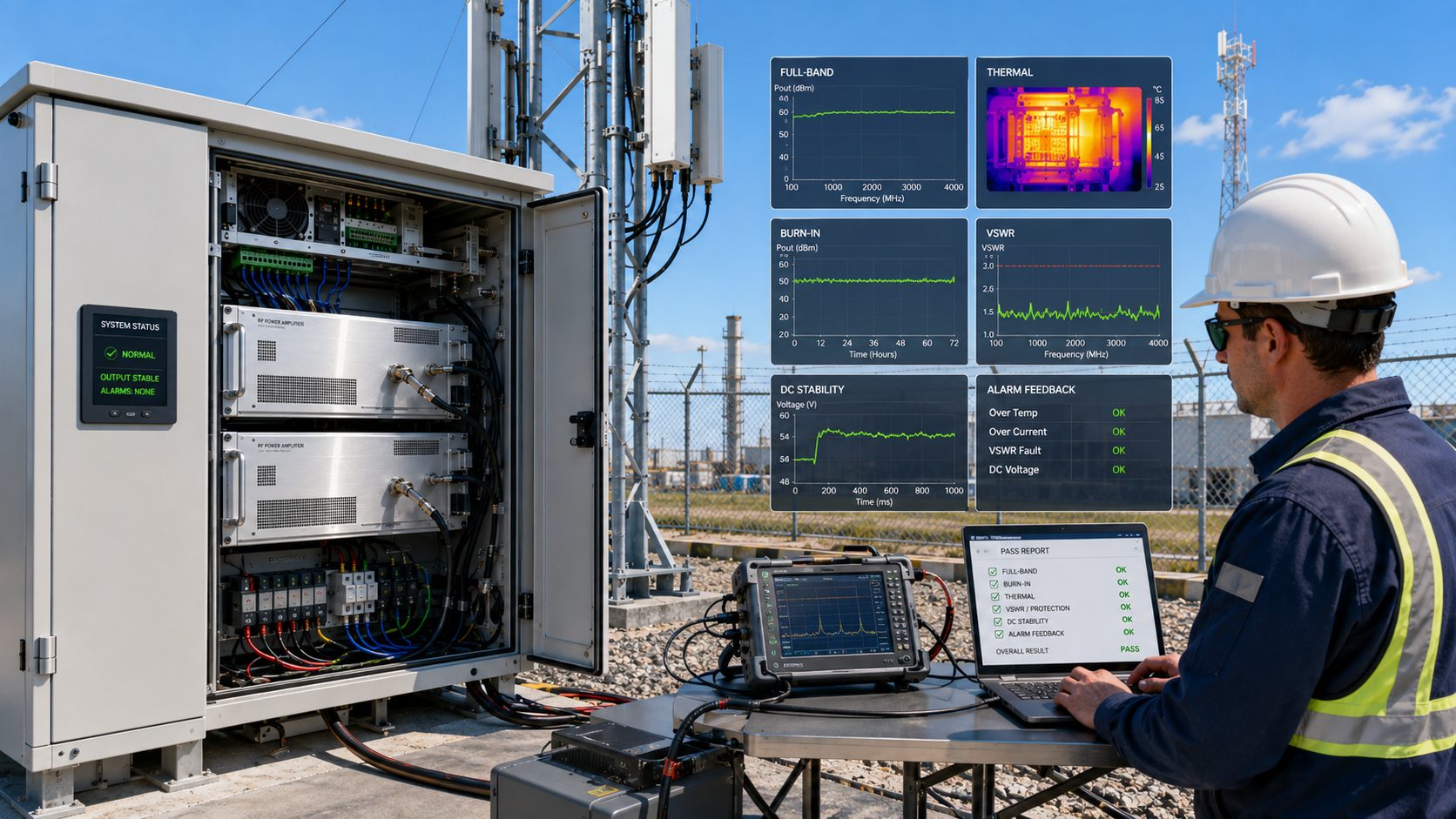
An RF Power Amplifier reliability test proves whether a module can keep stable output under repeated RF, thermal, electrical, load, and operating stress. In a real counter-UAS system, you may see normal output during a short bench check, then face alarms, heat drift, or weak coverage after installation. Here’s the deal: reliability means controlled behavior after stress appears, not only a clean power number on day one. A reliable module should pass full-band RF checks, long-duty burn-in, thermal stress, DC input variation, VSWR fault testing, alarm verification, and reviewable test data before deployment.
In practical factory validation, this kind of reliability check usually combines long-duty aging, high-low temperature storage, powered temperature operation, and vibration testing, so engineers can see whether the module remains stable after electrical, thermal, and mechanical stress.
1. How to Define RF Power Amplifier Reliability
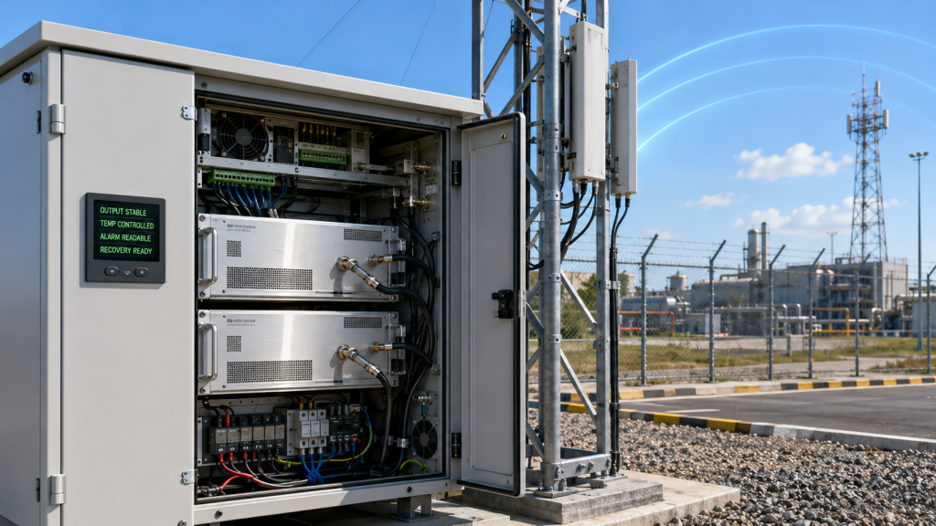
RF Power Amplifier reliability means predictable output, protection behavior, and recovery under real operating stress. It does not only mean that a module turns on, reaches rated power once, or survives a short lab demonstration. In a counter-UAS cabinet, vehicle-mounted jammer, or fixed perimeter system, reliability includes stable power, controlled gain drift, safe thermal response, fault alarms, and repeatable behavior after multiple power cycles. For projects using RF Power Amplifier modules inside broader defense systems, this definition gives you a better acceptance standard than a single specification line.
What Should Reliability Include?
A reliable module should behave consistently when conditions change. What’s the real story? You are not only buying output power; you are buying repeatable behavior across stress cases.
Stable output power across rated conditions
Gain that does not drift beyond project limits
Controlled case temperature during long-duty work
Protection logic that reacts before damage occurs
Alarm feedback that system controllers can read
Recovery after fault removal
How Does This Affect Your System?
Your system depends on every RF block acting predictably. This is where it gets practical: one unstable amplifier can create coverage gaps, late integration changes, or failed acceptance testing.
Reliability Area
What It Proves
User Value
Output stability
RF energy remains controlled
More predictable coverage
Thermal behavior
Heat does not cause runaway drift
Safer long-duty operation
Protection logic
Faults trigger before damage
Lower field failure risk
Alarm feedback
Controller sees module status
Faster troubleshooting
Key Takeaway: Treat reliability as tested behavior under stress, not as a marketing word. This helps you compare suppliers by evidence rather than claims.
2. What Makes RF Power Amplifier Power Testing Limited?
One-time RF Power Amplifier testing is not enough because it only confirms basic function under narrow conditions. A module may pass at 25°C, on a 50Ω dummy load, at one center frequency, for a few minutes. That result does not prove stability during high heat, wideband operation, long-duty output, voltage movement, antenna mismatch, or multi-module startup. Here’s the catch: a short bench test can confirm that a unit works, but it cannot prove that it will stay controlled after real system stress begins.
What Can a Short Bench Test Miss?
A short test often hides weak points. You might be wondering: what exactly can slip through if output power looks fine?
Hotspot growth after longer operation
Output drift at band edges
Connector temperature rise
Protection thresholds that trigger too early
Recovery problems after repeated faults
Voltage sensitivity under real DC feeds
How Should You Read One Power Number?
A power number only matters with test conditions attached. Here’s a better way to judge it: ask where, how long, at what temperature, at which frequency, and under what load condition.
Test Detail
Weak Report
Better Report
Frequency
One center point
Low, middle, high, swept data
Load
Perfect dummy load only
Dummy load plus mismatch cases
Time
Short startup check
Long-duty burn-in record
Temperature
Room temperature
Hot, cold, and recovery data
Key Takeaway: A one-time pass can start qualification, but it should never finish it. You need stress evidence before trusting a module in a real system.
3.How to Verify RF Power Amplifier Full-Band Stability
Full-band RF Power Amplifier testing helps reveal weak frequency zones that a center-frequency test can hide. Wideband modules such as 300–1200MHz, 300–2700MHz, or 2000–6000MHz should not be judged by one comfortable test point. A reliable test checks output power, gain trend, reflected behavior, efficiency, and temperature response across low, middle, and high points. Here’s the deal: full-band testing turns a broad frequency claim into visible performance evidence.
What Should Full-Band Testing Measure?
Full-band testing should show how output behaves across a range, not only at one point. Ready for the useful part? Weakness often appears near edges.
Output power at low, middle, and high frequencies
Small-signal gain trend
Gain flatness across target range
Efficiency movement across band
Reflected power condition
Temperature response at stressed points
Why Does This Matter for Wideband Systems?
Wideband systems often face different RF loads across different channels. What’s the real story? A flat-looking datasheet can still hide one zone that runs hotter or lower.
Full-Band Item
What It Finds
Risk Reduced
Swept gain
Drift and uneven response
Weak band-edge coverage
Output curve
Power drop zones
Failed acceptance checks
Efficiency trend
Hot operating zones
Thermal overload
Reflected response
Match-sensitive areas
PA stress under antenna load
Key Takeaway: Full-band testing gives you a map of behavior. That map helps you avoid buying a module that only performs well at one easy frequency.
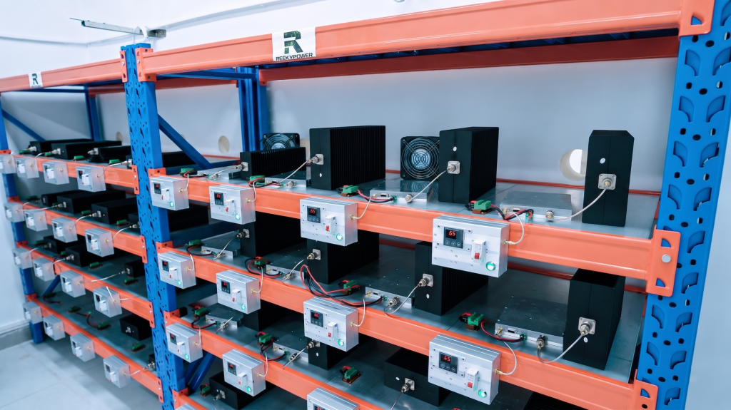
4. How to Review RF Power Amplifier Burn-In Results
Burn-in testing reveals RF Power Amplifier defects by forcing long-duty operation before shipment or integration. A module that works for five minutes may still show power sag, heat accumulation, solder stress, fan weakness, connector rise, or protection cycling after hours of continuous operation. This is where it gets interesting: burn-in does not make a module look stronger; it exposes early failure risks before they reach your cabinet. For high-power RF systems, this matters because hidden instability often appears only after heat and time combine.
In our factory-side validation, RF modules can be loaded at room temperature for 12 hours under controlled output conditions, so engineers can watch for power drift, abnormal current rise, connector heating, or early failure before shipment.
What Problems Show Up During Burn-In?
Burn-in makes time part of the test. Here’s why that matters: some failures need heat soak before they appear.
Gradual output power decline
Hotspot growth near power devices
Connector or DC terminal heating
Fan or airflow weakness
Protection threshold cycling
Early component stress failure
What Should Engineers Track?
Engineers should track both output and operating condition. The point is simple: power data without temperature data tells only half the story.
Burn-In Record
Why It Matters
Good Sign
Output over time
Shows drift or drop
Stable curve
Case temperature
Shows heat balance
Temperature convergence
Current draw
Shows electrical stress
No abnormal rise
Alarm history
Shows fault behavior
No repeated false trips
Key Takeaway: Burn-in catches hidden defects before field work starts. That gives you stronger confidence in long-duty RF operation.
5. What Thermal Tests Prove RF Power Amplifier Stability?
Thermal RF Power Amplifier testing matters because heat changes output, gain, protection behavior, and recovery. A module may work well at room temperature but drift when enclosure heat, outdoor sun, cabinet airflow, and continuous CW load become part of operation. Thermal testing checks whether output remains controlled as temperature rises and whether protection triggers at safe thresholds. Here’s the practical angle: you are not only testing heat resistance; you are testing whether RF output remains usable after heat becomes normal.
A practical thermal reliability check should not stop at room-temperature output. It can include -55°C low-temperature storage, +85°C high-temperature storage, and powered operation after temperature recovery to verify whether RF output returns to a stable state.
What Should Thermal Testing Check?
Thermal testing should cover hot operation, cooldown, and repeat cycles. You might be wondering: what separates a useful thermal test from a simple temperature reading?
Output stability at elevated temperature
Case temperature convergence
Gain movement after heat soak
Alarm trigger point
Shutdown behavior
Recovery after temperature falls
How Does Thermal Recovery Prove Stability?
Recovery matters because field systems rarely operate under perfect steady conditions. Here’s the real test: after a module protects itself, it should recover cleanly when conditions return.
Thermal Test
What It Confirms
User Benefit
Hot operation
Output under heat
Better field confidence
Heat soak
Drift after time
Fewer hidden failures
Alarm trigger
Protection timing
Safer output stage
Cooldown recovery
Restart behavior
Less manual service
Key Takeaway: Thermal testing proves whether heat creates controlled behavior or unstable behavior. For you, that means fewer surprises during long-duty deployment.
6. How Does Power Supply Testing Check Stability?
Power supply testing checks RF Power Amplifier stability by exposing output behavior to real DC input conditions. Clean lab supplies are useful, but deployed systems may use vehicle power, long cable runs, generators, shared DC buses, or multi-module startup events. A strong module should handle rated voltage, low boundary, high boundary, ripple, startup transient, and current surge without uncontrolled output or repeated alarms. Here’s the deal: stable RF output must be tested against real input behavior, not only ideal bench power.
What DC Conditions Should Be Tested?
DC stress testing should simulate normal and difficult supply states. What’s the catch? Many field faults start outside RF paths.
Rated voltage operation
Low-voltage boundary
High-voltage boundary
Startup inrush current
Multi-module simultaneous power-on
Power ripple and cable drop
How Do DC Faults Affect RF Output?
DC instability can cause RF sag, false alarms, or unstable enable behavior. This is where integration teams save time: early DC testing reduces late cabinet redesign.
DC Test Area
Failure It May Reveal
System Effect
Low voltage
Output collapse
Weak coverage
High voltage
Protection trigger
Unexpected shutdown
Ripple
RF instability
Noisy output behavior
Startup surge
Bus overload
Failed power sequence
Key Takeaway: Power supply testing links RF reliability with system power reality. That helps you avoid modules that only behave on a perfect lab supply.
7. How Does VSWR RF Power Amplifier Testing Protect PAs?
VSWR RF Power Amplifier testing protects power amplifier stages by proving how a module reacts to abnormal load conditions. Real antennas, cables, connectors, and outdoor installations rarely behave like a perfect dummy load. Load mismatch testing confirms reflected power detection, alarm output, power back-off, RF shutdown, and recovery after fault removal. Here’s the point: VSWR testing proves whether an antenna problem stays an antenna problem or becomes a burned PA problem.
What Should Load Mismatch Testing Include?
Mismatch testing should be deliberate and controlled. Ready for the practical list? A useful test checks both fault response and recovery.
Reflected power detection
High VSWR alarm
Power reduction behavior
RF shutdown condition
Open-load or poor-load reaction
Repeated fault cycling
Recovery after mismatch removal
Why Is Recovery Part of Protection?
Protection without recovery can still create system downtime. What’s the real story? A field team needs safe shutdown plus predictable return behavior.
VSWR Test
What It Proves
Why You Care
Alarm trigger
Fault detection works
Faster diagnosis
Power back-off
PA stress falls
Lower damage risk
Shutdown
Severe fault control
Safer operation
Recovery
Logic resets cleanly
Less service time
Key Takeaway: VSWR testing proves ruggedness when the RF path becomes imperfect. This protects output devices and reduces field replacement risk.
8. What Environmental Tests Matter for RF Power Amplifier Reliability?
Environmental tests for RF Power Amplifier reliability include hot storage, cold storage, powered temperature operation, thermal cycling, vibration, humidity, dust influence, salt-fog awareness, and transport shock checks. Lab output must connect with deployment reality, especially for outdoor fixed sites, vehicle systems, border equipment, and coastal security projects. Environmental testing should not read like a military standards catalog; it should answer whether RF behavior remains controlled after stress. Here’s the practical goal: connect lab performance with real working conditions.
For outdoor, vehicle-mounted, or transportable RF systems, environmental testing may combine -55°C storage, +85°C storage, powered operation near -40°C and +50°C, and vibration testing across X, Y, and Z directions from 15Hz to 2000Hz.
Which Environmental Tests Are Most Useful?
Useful environmental tests should match expected deployment conditions. You might be wondering: which tests matter most for RF modules?
High-temperature storage
Low-temperature storage
Powered hot operation
Powered cold operation
Thermal cycling
Vibration testing
Humidity exposure
Transport shock review
How Should Outdoor Risk Shape Testing?
Outdoor sites add enclosure heat, moisture, vibration, and airflow changes. This is where project context matters: a coastal tower and a vehicle cabinet may need different risk checks.
Environment Risk
Test Focus
Deployment Value
Heat
Powered high-temperature run
Stable summer operation
Cold
Low-temperature startup
Winter readiness
Vibration
Mechanical and connector stress
Vehicle reliability
Humidity
Insulation and corrosion risk
Outdoor confidence
Key Takeaway: Environmental testing turns lab data into deployment evidence. You get a clearer view of whether a module fits your actual operating scene.
9. How Does Alarm RF Power Amplifier Testing Confirm Safety?
Alarm RF Power Amplifier testing confirms safety by proving that protection circuits trigger, report, shut down, and recover correctly. Reliability is not only about preventing damage inside a module; it also means your controller must know what happened. A system using SDR control, enable logic, or cabinet-level monitoring needs readable alarm behavior for over-temperature, over-current, over-voltage, under-voltage, and VSWR faults. Here’s the deal: protection circuits are only reliable after their full behavior has been tested.
What Alarm Behaviors Should Be Verified?
Alarm testing should check both electrical signal and system interpretation. What’s the catch? An alarm that triggers but cannot be read still creates troubleshooting pain.
Over-temperature alarm
Over-current alarm
Over-voltage alarm
Under-voltage alarm
VSWR alarm
Enable shutdown
Fault reset
Controller reading accuracy
Why Should Alarm Logic Match System Control?
A module may protect itself while the system remains blind. This is where integration quality shows: alarms must match controller logic, timing, voltage level, and fault reset rules.
Alarm Test
What It Confirms
User Benefit
Trigger point
Fault threshold works
Safer operation
Output level
Controller can read alarm
Easier integration
Shutdown action
RF output stops safely
Lower damage risk
Reset behavior
System returns cleanly
Faster recovery
Key Takeaway: Alarm testing proves that safety logic works beyond the module. You gain clearer status control and faster fault handling.
10. What Data Should RF Power Amplifier Test Reports Show?
Engineers should review RF Power Amplifier test data that shows conditions, limits, curves, alarms, and pass/fail criteria. A useful report should not only say “pass.” It should show what was tested, where it was tested, how long it ran, how output behaved, and what changed before and after stress. Your team should ask for test frequency points, output curve, gain stability, efficiency data, temperature curve, burn-in duration, VSWR response, voltage/current limits, alarm behavior, and environmental conditions. Here’s the useful filter: evidence beats claims.
A useful reliability report should record not only pass/fail status but also test duration, temperature limits, vibration range, load condition, output behavior, and final electrical performance after recovery.
What Should a Strong Report Show?
A strong report should connect test setup with measured result. Ready for the checklist? You want traceable data, not vague approval text.
Tested frequency points
Output power curve
Gain stability record
Efficiency trend
Temperature curve
Burn-in duration
VSWR fault response
Alarm trigger behavior
Before/after comparison
How Should You Use Test Data Before Buying?
Use test data to compare risk, not only price. What’s the real story? Better documentation helps your engineers predict integration behavior before procurement.
Data Type
What It Shows
Buying Decision Value
Power curve
Output consistency
Confirms usable RF level
Temp curve
Heat balance
Predicts long-duty behavior
VSWR record
Fault survival
Reduces PA failure risk
Alarm log
Protection logic
Supports system control
Burn-in record
Time-based stability
Reduces early failure risk
Key Takeaway: A reliability report should help you decide with evidence. If data lacks conditions, curves, or fault behavior, your risk remains hidden.
Final Reliability Decision
RF Power Amplifier reliability testing should answer one direct question: will this module keep controlled behavior after real stress begins? This article covered reliability meaning, short-test limits, full-band checks, burn-in, thermal stress, DC input stress, VSWR faults, environmental testing, alarm logic, and report review. Here’s the final point: a reliable RF module is not proven by one attractive output number; it is proven by repeated evidence under stress. If you need RF modules, SDR sources, antennas, and integration support for counter-UAS or mission-critical systems, contact us today and bring your test requirements to a source factory built around verified RF behavior. Our position is clear: mission-critical RF systems deserve measured proof, not hopeful assumptions.
FAQ
Can I judge RF Power Amplifier reliability by rated power alone?
No, rated power alone cannot prove reliability. Rated power only shows a target output level under defined conditions. You also need full-band data, temperature behavior, burn-in results, DC input tolerance, VSWR response, alarm logic, and environmental stress records before trusting a module in a real system.
What’s the best RF Power Amplifier test before integration?
The best single test is a combined full-band and long-duty test. That pairing shows whether output remains stable across frequency and time. For stronger confidence, add thermal monitoring, DC input variation, VSWR mismatch checks, and alarm verification before cabinet integration.
How do I know if an RF Power Amplifier burn-in test is useful?
A useful burn-in test records output power, temperature, current, alarms, duration, and pass/fail limits. A simple statement that a unit was aged is not enough. You need data showing whether output drifted, heat stabilized, and faults appeared during continuous operation.
Can I use a dummy load test as final acceptance?
No, a dummy load test should not be final acceptance by itself. It gives a clean baseline, but real systems include antennas, cables, connectors, temperature change, and power variation. Use dummy load data as one part of a wider reliability test plan.
How do I know if a reliability report is strong enough?
A strong report shows test conditions, measured curves, stress duration, fault response, and before/after comparison. If it only says “pass” without frequency points, load conditions, temperature data, alarm behavior, or burn-in records, it does not give your engineering team enough evidence.
Contents
About Our Company
RF SKYPOWER is a Source Factory engineering precision RF modules, antennas, SDR signal sources, and detection systems built exclusively for defense, security, and critical infrastructure applications.
When R&D, manufacturing, and testing happen under one roof, you get unmatched quality control and supply chain stability.