


RF Power Amplifier control interface design helps system integrators manage enable control, alarm feedback, power adjustment, thermal response, and fault recovery safely. In a vehicle-mounted counter-UAS platform, a PA module may pass bench output tests but still fail during live integration if the controller cannot read alarms, sequence enable timing, monitor reflected power, or reduce output under heat stress. The problem is not always weak RF output; it is often blind system control. This guide explains how to connect RF Power Amplifier modules with control boards, monitoring software, communication interfaces, protection logic, and acceptance testing so the whole platform behaves predictably under real operating conditions.
1. What Is an RF Power Amplifier Control Interface?
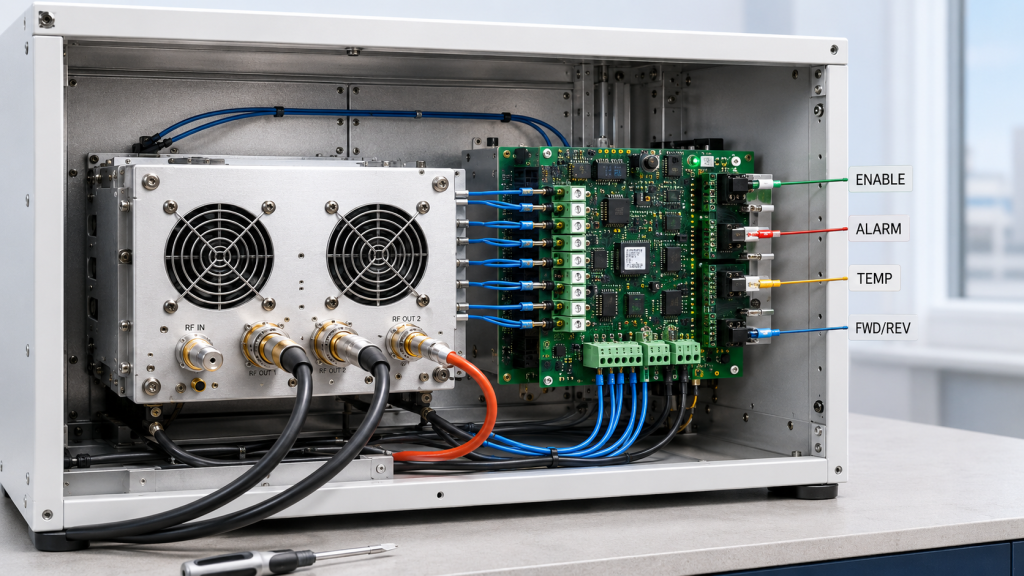
An RF Power Amplifier control interface is the control and feedback path between a PA module and the system controller. It is not the RF output port, and it is not only the DC input. What’s the real story? This interface tells your controller whether the module can turn on, what condition it is in, and whether output should continue.
What Signals Belong in This Interface?
A useful interface usually combines simple logic pins, analog feedback, and protocol-based data. You do not need every signal in every project, but you do need enough visibility for safe operation.
- Enable control
- Alarm output
- Temperature feedback
- Forward power feedback
- Reflected power feedback
- Current and voltage status
- Power adjustment
- Fault reset or shutdown control
How Does This Help Your System Decide?
A control interface helps your system stop guessing. Here’s the useful part: once your controller can read module status, it can trigger actions instead of waiting for field failure.
| Interface Signal | System Use |
|---|---|
| Enable | Turns RF output on or off |
| Alarm | Triggers fault handling |
| Temperature | Guides thermal control |
| Forward power | Confirms output state |
| Reflected power | Flags load mismatch |
| Fault reset | Supports recovery logic |
Key Takeaway: A control interface turns a standalone RF Power Amplifier module into a managed system component, which helps you build safer RF equipment.
2. Why Do RF Power Amplifier Modules Need Enable Control?
An RF Power Amplifier module needs enable control because RF output should happen only when system conditions are ready. Your controller may need to check signal source status, DC voltage, cooling, antenna path, and task mode before output begins. Here’s the deal: enable control turns RF output into a managed system action, not a random power event.

When Should Enable Stay Off?
Enable should stay off when any supporting condition looks unsafe or incomplete. In a counter-UAS rack, that may mean no valid waveform, unstable 28 V supply, a high-temperature state, or an antenna path still switching.
- No valid RF input signal
- Power supply outside allowed range
- Antenna relay not settled
- Cooling fan not active
- Over-temperature alarm present
- Operator has selected standby mode
How Should Enable Timing Be Planned?
Enable timing should follow a clear sequence: controller boots, power stabilizes, RF source becomes valid, PA enable turns on, and feedback confirms output. This is where it gets practical: wrong timing can stress the source chain or create false alarms during startup.
| Control Step | Reason |
|---|---|
| Power controller | Starts logic safely |
| Check DC rail | Prevents low-voltage output |
| Validate RF input | Avoids empty transmission |
| Apply enable | Starts PA action |
| Read feedback | Confirms actual output |
| Log status | Helps maintenance |
Key Takeaway: Enable control helps you prevent accidental output, protect upstream hardware, and create a cleaner startup sequence.
3. How Do RF Power Amplifier Alarm Signals Protect Systems?
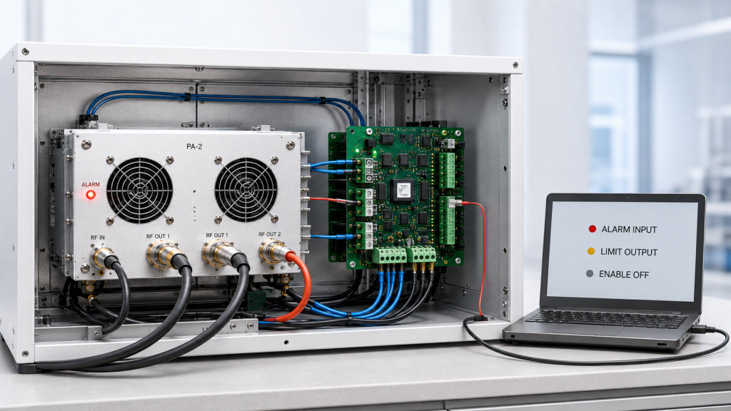
An RF Power Amplifier alarm signal protects systems by telling the controller that module behavior has crossed a warning or fault limit. Alarm feedback should not exist only for a front-panel LED. Here’s the point: alarm signals should feed logic that can reduce drive, disable output, switch modules, alert operators, or enter a safe mode.
Which Faults Should Alarm Logic Cover?
Alarm logic should cover electrical, thermal, RF load, and cooling risks. You do not need dramatic fault screens; you need clear signals that help software respond fast.
- Over-temperature
- Over-current
- Over-voltage
- Under-voltage
- High VSWR
- Reflected power alarm
- Fan failure
- Module fault
- Output shutdown
What Should the Controller Do After Alarm Input?
A controller should classify alarms instead of treating every fault the same. Ready for the good part? A warning may need power reduction, while a shutdown fault may need enable removal and operator review.
| Alarm Type | Suggested System Action |
|---|---|
| Temperature warning | Reduce output power |
| Temperature shutdown | Disable PA output |
| High reflected power | Stop RF output |
| Low voltage | Delay restart |
| Fan fault | Limit duty cycle |
| Unknown module fault | Log and lock output |
Key Takeaway: Alarm signals give your system a chance to act before hardware damage, weak coverage, or field downtime becomes serious.
4. What Status Feedback Should RF Power Amplifier Modules Provide?
An RF Power Amplifier module should provide status feedback for thermal state, RF output, reflected power, supply health, and fault identity. Alarm lines tell you something went wrong, but status feedback tells you how conditions are changing. What’s the catch? Without feedback, your controller can only assume the module is healthy.

Which Feedback Values Matter Most?
The most useful values depend on system risk, but several signals appear in most serious PA integrations. For counter-UAS and EW-style platforms, forward power and reflected power often matter because field antenna paths change under vibration, cable loss, or installation error.
- Temperature feedback
- Forward power feedback
- Reflected power feedback
- Voltage feedback
- Current feedback
- Fault code
- Enable status
- RF output status
How Does Feedback Support Closed-Loop Control?
Feedback supports closed-loop control because the controller can compare target state with actual state. Here’s why that matters: if forward power drops while current rises, the system can detect abnormal load behavior instead of showing a vague “fault” message.
| Feedback Type | What It Tells You |
|---|---|
| Temperature | Thermal margin |
| Forward power | Delivered output |
| Reflected power | Load quality |
| Voltage | Supply stability |
| Current | Consumption trend |
| Fault code | Failure category |
Key Takeaway: Status feedback helps you move from blind switching toward predictable control, faster troubleshooting, and cleaner acceptance testing.
5. How Does RF Power Amplifier Power Control Help Integration?
An RF Power Amplifier power control function helps integration by giving your system more than a simple on/off choice. Some systems should not transmit at full power during every task, distance, test mode, or thermal condition. Here’s the deal: power control lets software match output with real operating needs.
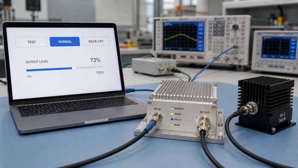
When Should Output Power Be Adjustable?
Power should be adjustable when your platform works across multiple coverage ranges, heat conditions, frequency bands, or duty cycles. For example, close-range tests may need reduced output, while field mode may need higher output after antenna and safety checks pass.
- Staged output levels
- Lower heat during standby
- Band-specific output targets
- Reduced current draw
- Controlled test mode
- Near-range and far-range modes
- Power back-off during protection events
What Control Methods Can Set Output Power?
Power control may use analog voltage, digital commands, gain steps, or source-side drive control. This is where integration gets easier: when the PA and controller share predictable control behavior, your software can manage output without field guesswork.
| Power Control Method | Best Use |
|---|---|
| Analog voltage | Simple level adjustment |
| GPIO steps | Preset output modes |
| UART command | Parameter setting |
| RS485 command | Multi-module bus |
| Ethernet command | Remote control |
| Source drive control | Coordinated RF chain |
Key Takeaway: Power control helps reduce thermal stress, save energy, support test modes, and create smoother system behavior.
6. Why Do RF Power Amplifier Communication Interfaces Matter?
An RF Power Amplifier communication interface matters because complex systems need structured status reading, parameter setting, and remote management. GPIO may suit basic enable and alarm functions, but larger platforms often need richer data. Here’s the real issue: control complexity rises as module count, software logic, and maintenance needs rise.
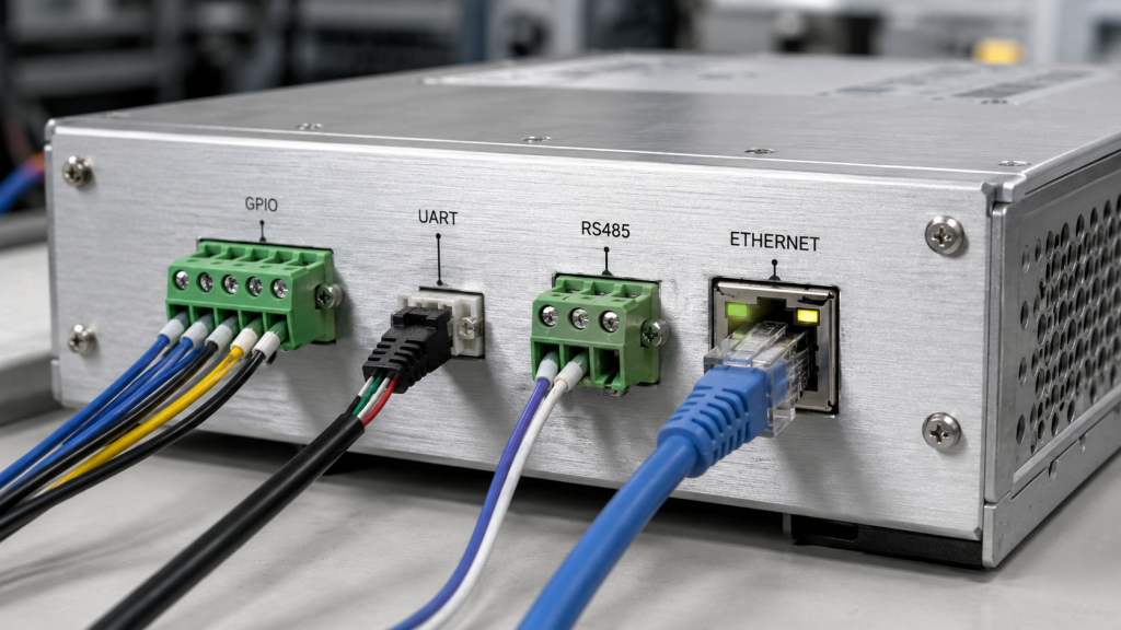
Which Interface Types Are Common?
Different projects use different interface layers. A compact handheld system may need GPIO, while a multi-band vehicle system may need RS485, UART, CAN, Ethernet, or AT commands.
- GPIO for enable and alarm
- TTL level control for simple boards
- UART for parameter reading
- RS485 for longer cable runs
- CAN for rugged system networks
- Ethernet for remote software control
- AT commands for readable module settings
- Analog voltage for gain or power tuning
How Should You Choose an Interface?
You should choose an interface by cable length, noise environment, module count, data depth, and controller capability. The practical answer is simple: basic systems can stay simple, but multi-module platforms need structured communication.
| Interface | Good Fit |
|---|---|
| GPIO | Basic enable or alarm |
| TTL | Short internal wiring |
| UART | Board-level status data |
| RS485 | Multi-drop control |
| CAN | Rugged vehicle networks |
| Ethernet | Remote supervision |
| AT command | Clear parameter setting |
Key Takeaway: Communication interfaces help you reduce wiring confusion, support remote diagnostics, and manage more PA modules from one controller.
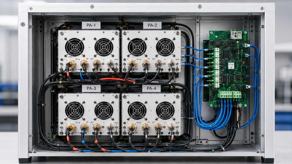
7. How Do RF Power Amplifier Interfaces Support Multi-Module Systems?
An RF Power Amplifier interface supports multi-module systems by giving every module a controlled enable path, alarm line, status channel, and power control method. A real counter-UAS platform may run several PA modules across low, mid, and high bands. Here’s where trouble starts: without unified control, one module fault can hide inside a messy system.
What Goes Wrong Without Unified Control?
Multi-module systems can fail in confusing ways when every PA behaves like an isolated box. You may see current surges, thermal imbalance, unclear alarms, or a module that stays active after a system mode changes.
- Startup order becomes chaotic
- Fault location becomes unclear
- Modules pull current at the same time
- Thermal behavior becomes uneven
- Remote maintenance becomes hard
- One alarm may be missed
- Software cannot show exact module state
What Should a Multi-Module Control Plan Include?
A multi-module control plan should define addresses, enable sequencing, alarm priority, power limits, and recovery behavior. Here’s the useful part: consistent interface logic lets one controller supervise many PA paths without custom handling for every band.
| Control Need | Multi-Module Benefit |
|---|---|
| Address mapping | Identifies each PA |
| Enable sequence | Reduces startup stress |
| Alarm priority | Handles severe faults faster |
| Power limits | Balances heat and current |
| Status polling | Supports remote checks |
| Fault recovery | Speeds maintenance |
Key Takeaway: Multi-module RF systems need shared control rules, not just more amplifier hardware.
8. How Does RF Power Amplifier Logic Link Protection and Heat?
An RF Power Amplifier control logic links protection and heat by turning sensor readings into system actions. Internal PA protection becomes more useful when the controller can read it and react. What’s the real story? A module may protect itself, but a full system needs to protect coverage, power supply, cables, antennas, and operators too.
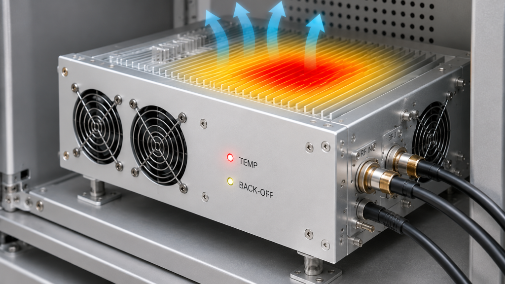
Which Conditions Should Trigger Control Actions?
Control actions should match fault severity. Temperature rise may call for staged power reduction, while severe VSWR may need instant output removal.
- High temperature: reduce power or disable enable
- Low voltage: delay startup
- High VSWR: shut RF output
- Reflected power rise: alert controller
- Fan fault: limit output time
- Current spike: enter protection state
- Repeated fault: lock until reset
How Should Software Handle Recovery?
Recovery logic should avoid endless restart loops. Here’s the engineering trap: if software keeps re-enabling a hot or mismatched module, protection becomes a cycle instead of a solution.
| Fault Condition | Better Recovery Logic |
|---|---|
| Temperature warning | Power back-off |
| Temperature shutdown | Wait for cooling |
| High reflected power | Require antenna check |
| Low voltage | Restart after stable rail |
| Over-current | Lock and log event |
| Fan fault | Limit duty cycle |
Key Takeaway: Protection logic works best when module data, power control, enable control, and thermal behavior act as one system.
9. What RF Power Amplifier Integration Mistakes Should You Avoid?
An RF Power Amplifier integration mistake to avoid is treating the PA as only a power device with RF input, RF output, and DC supply. Many failures start when control lines, alarms, and feedback are ignored. Here’s the hard truth: a module can be electrically strong but poorly integrated.
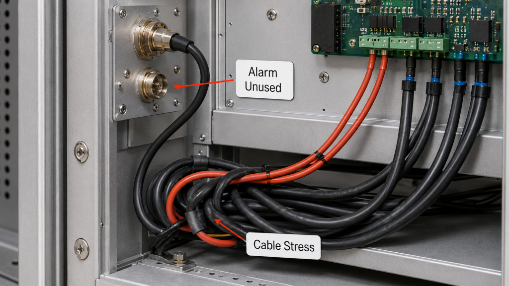
Which Wiring Mistakes Create Risk?
Wiring mistakes often appear late because bench tests do not match vibration, thermal load, cable bundles, or full-duty operation. Keep control lines readable, separated, and documented.
- Connecting DC and RF only
- Leaving alarm pins unused
- Routing control lines beside high-current cables
- Sharing control lines without isolation
- Ignoring level compatibility
- Missing pull-up or pull-down logic
- Weak connector strain relief
Which Software Mistakes Hurt Field Use?
Software mistakes can make good hardware look unreliable. Ready for the practical part? your HMI should show fault cause, module identity, recovery state, and action history.
| Mistake | Better Practice |
|---|---|
| Generic “fault” message | Show fault category |
| No reset logic | Define recovery sequence |
| No thermal trend | Log temperature curve |
| No alarm test | Test fault response |
| No module address | Identify exact PA |
| No warning state | Separate warning from shutdown |
Key Takeaway: Good integration checks wiring, logic, alarm handling, and operator visibility before full system acceptance.
10. How Should You Plan an RF Power Amplifier Control Interface?
An RF Power Amplifier control interface should be planned around enable behavior, alarm handling, feedback depth, power adjustment, compatibility, and load testing. You should define what the controller must know before RF output begins. Here’s the good part: a clear checklist prevents integration surprises during system commissioning.

What Questions Should Your Team Answer?
Your team should answer control questions before enclosure design, harness design, or software UI work becomes fixed. Late interface changes can force PCB revisions or field wiring patches.
- What signal enables RF output?
- What happens if enable is removed?
- Which alarms are available?
- Are alarms analog, digital, or protocol-based?
- Can the controller read temperature?
- Can it monitor forward and reflected power?
- Can output power be adjusted?
- What recovery method follows a fault?
- Has full sequence testing been done under load?
What Should Be Tested Before Acceptance?
Acceptance should test normal operation and fault response. This is where confidence comes from: you prove not only output power, but system behavior under stress.
| Test Item | What It Confirms |
|---|---|
| Enable sequence | Safe startup |
| Alarm response | Fault action works |
| Temperature feedback | Thermal data reads correctly |
| Power adjustment | Output can be managed |
| VSWR alarm | Load fault response works |
| Recovery sequence | Restart logic behaves safely |
Key Takeaway: A planned interface makes PA modules easier to integrate, safer to operate, and more predictable inside a complete RF system.
Final Thoughts
RF Power Amplifier integration is not only about output wattage. You now have a framework for enable control, alarm input, status feedback, communication protocols, multi-module control, thermal response, and acceptance testing. Here’s our stance: serious RF systems should be built around controllable, readable, and testable hardware, not blind power blocks. If you need RF modules that fit real control logic, contact us today and build your next system with a stronger engineering base.
FAQ
Can I integrate an RF Power Amplifier module with only DC and RF ports?
Yes, but it is a weak integration method for serious systems. Without enable, alarm, and feedback signals, your controller cannot react to heat, reflected power, voltage issues, or module faults.
What’s the best control method for a multi-module RF system?
A structured communication interface usually works best. RS485, UART, CAN, Ethernet, or AT commands help your controller identify each module, read status, and manage fault logic.
How do I know if my PA module needs power control?
You need power control if your system uses multiple modes, long-duty operation, close-range testing, thermal limits, or staged coverage. Power adjustment gives your controller more control than simple on/off switching.
Can I use GPIO for enable and alarm control?
Yes, GPIO works well for basic enable and alarm functions. For richer monitoring, you may need protocol-based communication or analog feedback lines.
How do I know if my control interface is ready for deployment?
It is ready when startup, shutdown, alarm response, power adjustment, temperature feedback, reflected power response, and recovery logic have all been tested under real load conditions.