


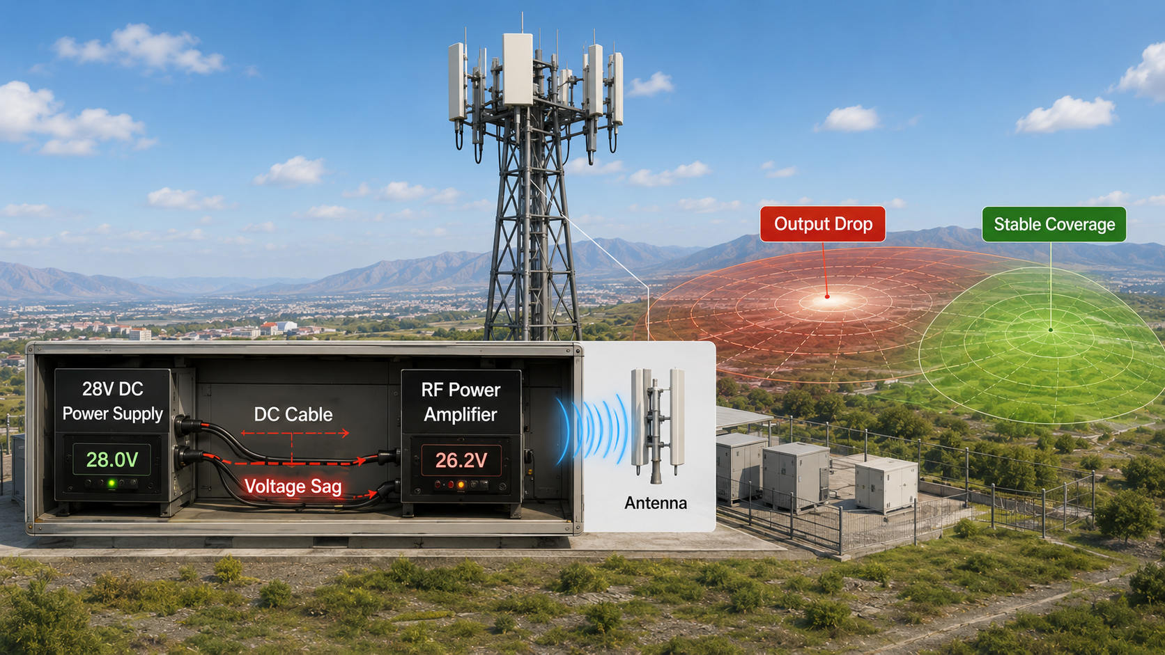
You power RF Power Amplifiers without output drops by stabilizing the DC input, sizing current capacity correctly, reducing voltage drop, controlling ripple, and testing the full power chain under real RF load. In a counter-UAS or drone jammer system, a module may test well on a clean bench supply, then lose output after installation because long cables, shared 28V rails, startup surge, or weak current reserve pull the DC input down. The RF module is not always the failure point; sometimes the power chain cannot support stable RF output.
Here’s the deal: stable RF output starts with stable DC input. If you want steady output power, lower thermal stress, fewer protection triggers, and more predictable field coverage, you need to treat the RF Power Amplifier as a high-power DC-to-RF conversion load, not just a component with a voltage label. This article explains how voltage stability, current capacity, ripple, grounding, startup behavior, power protection, and multi-module power planning help prevent RF output drops before they become field failures..
1. How to Prevent RF Power Amplifier Output Drops
RF Power Amplifier output drops usually happen because the module cannot receive stable DC power under real load. A 28V supply may look correct during setup, but output can fall when current demand rises, cable voltage drop increases, ripple enters the DC rail, or several modules start together. What’s the real story? The RF module may not be weak; the power chain may be unable to support continuous DC-to-RF conversion.
Why does a power issue look like an RF failure?
A power issue looks like an RF failure because the symptom appears at the RF output port, not at the power supply label. You may see lower output power, gain drift, temperature rise, protection alarms, or unstable coverage, while the actual cause sits in voltage delivery, current reserve, wiring, or grounding.
- Input voltage drops at the module terminal
- Current capacity is too close to the load demand
- DC ripple disturbs RF output behavior
- Long cables create resistance loss
- Shared power rails pull modules down together
- Startup surge triggers protection logic
- Poor grounding adds noise or reference instability
Key Takeaway: If RF output drops, test the DC power chain under full RF load before you judge the amplifier module itself.
| Cause | What Happens | Field Result |
|---|---|---|
| Voltage drop | Module receives less than expected | RF output falls |
| Weak current reserve | Supply cannot hold load | Power becomes unstable |
| Ripple or noise | DC rail disturbs RF behavior | Signal quality may degrade |
| Poor wiring | Resistance and heat increase | System efficiency drops |
This section now matches the new title because it starts with “output drops” first, then brings the reader back to your real topic: DC power stability.
2. What Causes RF Power Amplifier Output Drops?
RF Power Amplifier output depends on DC input because the module converts DC energy into RF power through active devices, bias networks, and control circuits. If DC power becomes weak or noisy, RF output cannot remain stable under long-duty operation. Here’s the simple rule: an amplifier cannot deliver stable RF power from an unstable power source.
How does weak DC input show up in RF behavior?
Weak DC input often looks like an RF problem because symptoms appear at output ports, spectrum instruments, thermal sensors, or system coverage tests. You may see power drift, uneven output, unexpected alarms, or signal quality changes, even when the amplifier hardware itself remains functional.
- RF output power drop
- Gain fluctuation
- Efficiency change
- Higher thermal stress
- Protection trigger events
- Controller instability
- Spectrum noise floor movement
Key Takeaway: Before you replace a module, check whether input power quality caused the RF symptom.
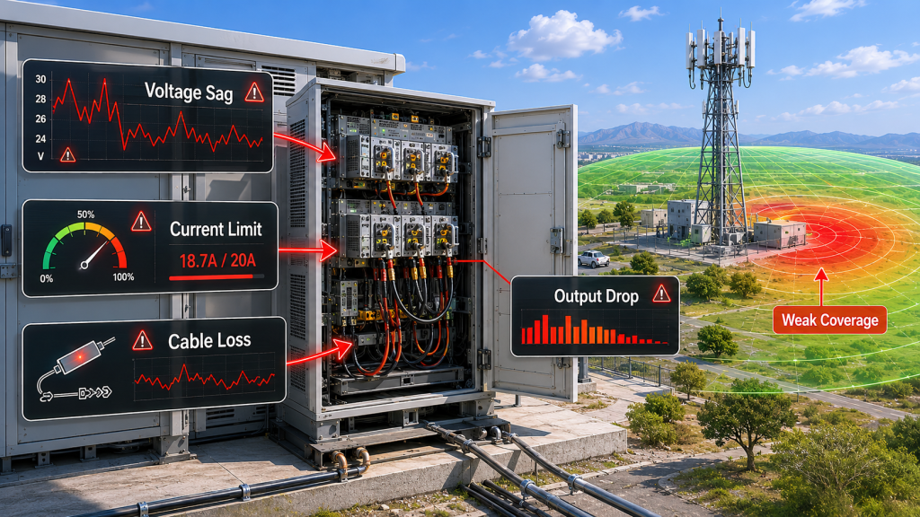
| DC Input Issue | RF Output Symptom | Field Effect |
|---|---|---|
| Voltage sag | Lower RF power | Shorter coverage |
| Current limit | Output compression | Unstable operation |
| Ripple | Amplitude disturbance | Noisier signal |
| Supply reset | Module restart | Coverage gap |
The pattern is clear: RF trouble often starts on the DC side.
3. How to Check Voltage Drop in an RF Power Amplifier
Voltage drop affects RF Power Amplifier performance by lowering actual module input voltage below the power supply setting. You may set 28V at the source, yet the module may receive 26V or less after long cable runs, small wire gauge, connector resistance, or shared current demand. This is where it gets expensive: field teams may blame RF hardware while the real loss sits in the DC path.
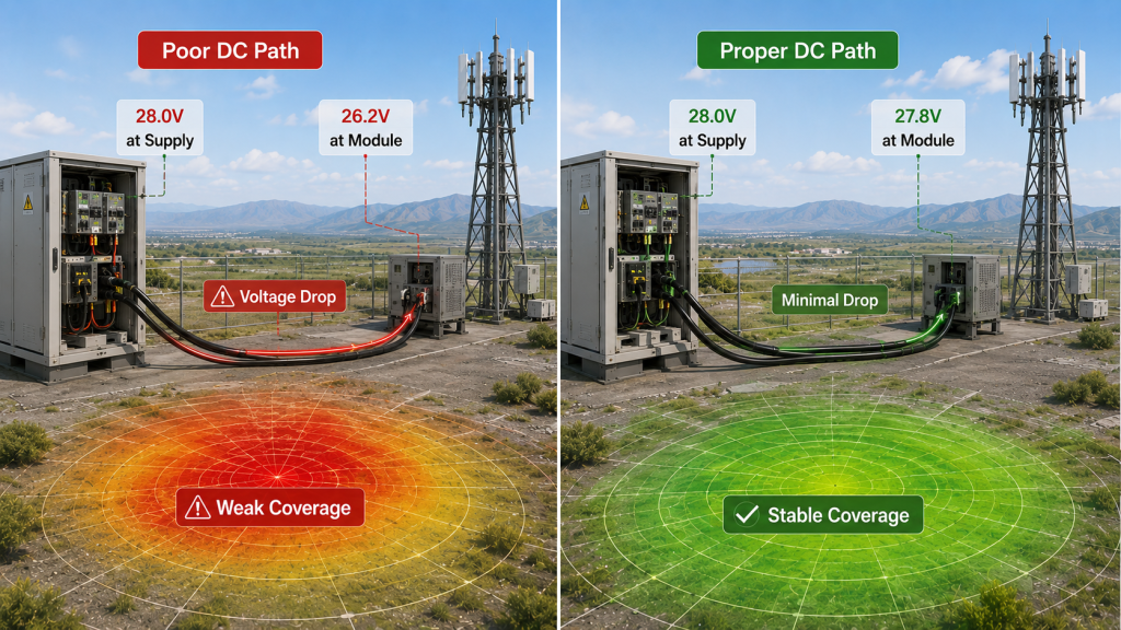
Why can 28V become much lower at the module?
Voltage drop rises when current rises, so high-power modules create a tougher test than idle measurements. Multi-band counter-UAS racks make this worse because several amplifiers may start or operate at high load together.
- Long DC cables
- Thin wire gauge
- High connector contact resistance
- Shared power rails
- Multi-module startup surge
- Vehicle battery fluctuation
- Poor crimping or loose terminals
Key Takeaway: Measure voltage at the module terminals during full RF load, not only at the power supply output.
| Situation | Likely Result | Practical Check |
|---|---|---|
| Long cable | DC drop | Measure both cable ends |
| Thin wire | Cable heating | Verify current rating |
| Shared rail | Module interaction | Test simultaneous load |
| Loose connector | Intermittent sag | Inspect contact resistance |
A voltage map under full load gives you better evidence than a static 28V label.
4. What Current Capacity Does an RF Power Amplifier Need?
Current capacity matters for RF Power Amplifier modules because voltage only tells you the level, while current reserve tells you whether the supply can hold that level under load. A supply can read 28V with no load, then collapse when a high-power module asks for current. Here’s the catch: insufficient current does not always shut the system down immediately; it can create unstable output that looks random.

What current data should you request?
You should request maximum current, peak current, average current, startup surge, and operating mode data. For pulsed systems, sweep sources, or multi-band jamming equipment, peak demand may matter more than steady average draw.
- Maximum current at rated RF output
- Peak current during enable
- Average current during duty cycle
- Startup inrush behavior
- Current draw during sweep or pulse mode
- Current limit behavior from supply
Key Takeaway: Current reserve protects RF stability when load demand rises quickly or several modules operate together.
| Power Supply Label | Hidden Question | Why It Matters |
|---|---|---|
| 28V DC | At what load? | Idle voltage can mislead |
| 20A | Continuous or peak? | Thermal limits differ |
| Current limit | Soft or hard limit? | Output may sag |
| Power rating | At what temperature? | Field conditions change |
If you size only by voltage, your system may pass setup and fail under real RF load.
5. What Ripple Does to RF Power Amplifier Signals
Ripple and noise affect RF Power Amplifier signals by disturbing bias, control circuits, and supply rails that support RF output behavior. Clean DC power helps support cleaner RF operation, especially in wideband modules and signal-sensitive systems. You might be wondering: does small power ripple always matter? It depends on amplitude, frequency, filtering, grounding, and module architecture.

Where can ripple create trouble?
Ripple may enter through insufficient filtering, overloaded supplies, poor grounding, long cables, or switching converters placed too close to RF paths. In compact drone jammer modules, DC noise can combine with heat, current stress, and control logic sensitivity.
- Output amplitude fluctuation
- Raised RF noise floor
- Spur risk in some operating states
- Control circuit misreadings
- Protection status fluctuation
- Thermal behavior changes
- Lower confidence during acceptance testing
Key Takeaway: Low ripple power design helps make RF test results repeatable across bench, vehicle, and field environments.
| Ripple Source | Possible RF Effect | Control Method |
|---|---|---|
| Switching supply | Noise coupling | Filtering and layout |
| Shared DC rail | Load modulation | Power segmentation |
| Long cable | Impedance effects | Local decoupling |
| Ground loop | Noise path | Ground planning |
Ripple control does not replace RF design, but it gives RF design a cleaner operating base.
6. What Happens During Startup and RF Power Switching?
Startup and RF power switching can stress RF Power Amplifier modules because load demand changes faster than many DC supplies can recover. A module may be stable after startup but unstable during enable, pulse transitions, sweep changes, or protection recovery. Ready for the good part? transient testing often reveals problems that steady-state testing misses.
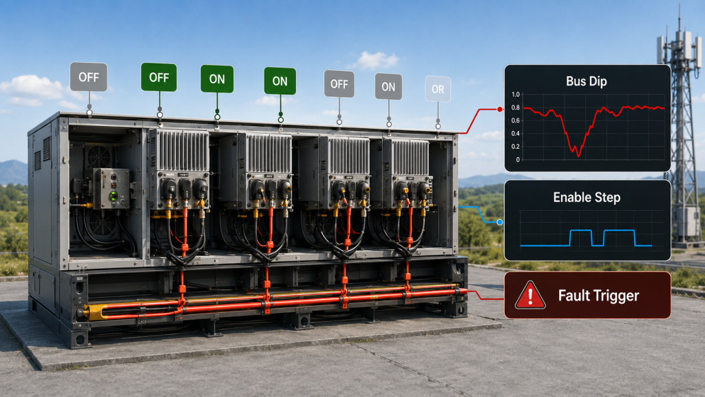
Which transient events deserve attention?
Transient events matter because RF modules may not behave like fixed resistors. Enable timing, high-power biasing, control logic, and simultaneous module startup can create fast current steps across the DC bus.
- Power-on inrush
- RF enable current rise
- Pulse load transitions
- Sweep-mode load movement
- Multi-module simultaneous startup
- Fault recovery restart
- Output power adjustment
Key Takeaway: A power chain should recover quickly from current steps without pulling control circuits or other modules below safe voltage.
| Event | Supply Challenge | Failure Sign |
|---|---|---|
| Startup | Inrush current | Bus dip |
| Enable | Fast load step | False alarm |
| Pulse mode | Repeated demand | Output ripple |
| Restart | Recovery surge | Controller reset |
Transient response testing gives you a more realistic picture than a single full-power reading.
7. How Do Grounding and Cable Layout Affect RF Power Amplifier Stability?
Grounding and cable layout affect RF Power Amplifier stability because power delivery depends on impedance, return paths, connector quality, and physical routing. A good power supply can still perform poorly if DC cables are too long, ground return paths are weak, or control wiring shares noisy current paths. Here’s what many teams miss: power stability is also a wiring problem.
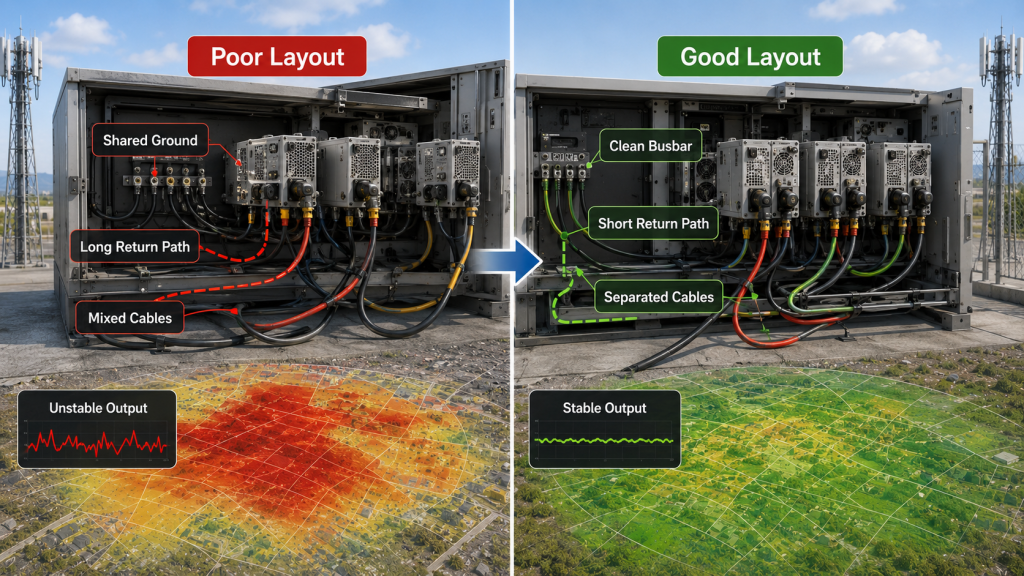
What layout choices reduce power-chain risk?
Strong layout keeps high current paths short, predictable, and separated from sensitive control signals. In multi-module systems, star wiring or busbar distribution can reduce unwanted interaction between modules.
- Match DC positive and negative wire capacity
- Use low-resistance connectors
- Keep high-current loops short
- Separate control lines from high-current cables
- Avoid thin shared ground returns
- Consider busbar or star distribution
- Check connector temperature after load testing
Key Takeaway: Better cable and grounding design helps you avoid unstable RF output caused by hidden power-path impedance.
| Layout Choice | Benefit | Risk Reduced |
|---|---|---|
| Short DC path | Lower drop | Output drift |
| Proper wire gauge | Less heating | Efficiency loss |
| Strong return path | Cleaner reference | Noise coupling |
| Star distribution | Lower interaction | Module pull-down |
A clean wiring architecture often solves problems that look like amplifier instability.
8. Why Do Multi-Module RF Power Amplifier Systems Need Power Budgets?
Multi-module RF Power Amplifier systems need power budgets because one stable module does not prove that an entire rack stays stable when all modules operate together. Counter-UAS equipment may combine low-band, mid-band, and high-band modules with different current profiles. This is where planning pays off: total DC demand, cable drop, thermal load, and protection timing must be designed as one system.
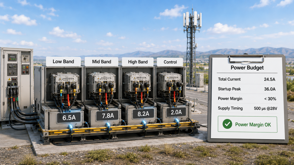
What should a system power budget include?
A practical power budget should cover steady load, peak load, simultaneous operating states, wiring losses, and thermal impact. You should also review how one module’s state change affects other modules sharing the same rail.
- Maximum current per module
- Number of simultaneous active modules
- Total supply wattage margin
- Peak startup demand
- Cable and connector ratings
- Bus voltage drop
- Cooling and supply efficiency
- Fault coordination logic
Key Takeaway: Multi-module systems need system-level DC planning before RF coverage can be trusted.
| Budget Item | Why It Matters | Check Method |
|---|---|---|
| Total current | Prevents bus sag | Sum worst-case loads |
| Startup demand | Avoids reset | Sequence enable timing |
| Cable rating | Reduces heat | Verify ampacity |
| Supply margin | Handles peaks | Load-bank test |
A power budget turns scattered module data into a usable system design.
9. What Protection Features Should RF Power Amplifier Power Have?
RF Power Amplifier power protection should make abnormal supply conditions controlled, visible, and recoverable instead of sudden and destructive. Protection should not exist only inside the module; the external DC supply and system controller should coordinate with amplifier thresholds. Here’s the practical angle: good protection helps field teams diagnose power faults faster.
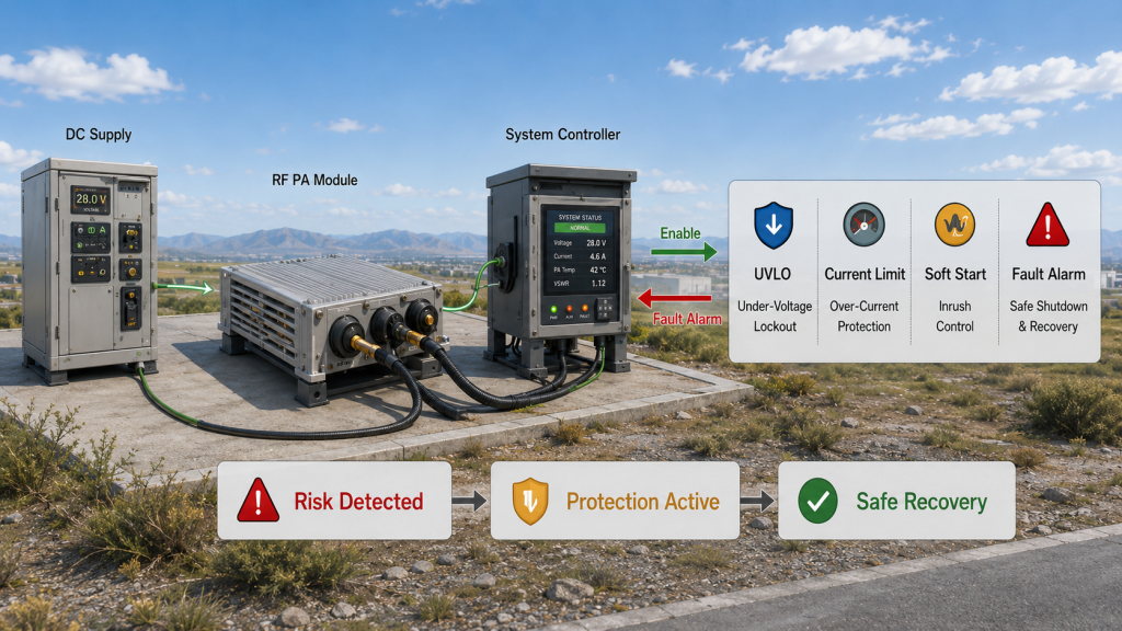
Which protection functions should you review?
Power-related protection should cover both supply-side and module-side risks. That includes voltage limits, current behavior, polarity mistakes, enable control, and alarm visibility.
- Under-voltage protection
- Over-voltage protection
- Over-current limiting
- Reverse polarity protection
- Soft-start behavior
- Fault alarm output
- Enable control logic
- Temperature-linked derating
- Shutdown and recovery rules
Key Takeaway: Power protection should prevent damage while giving you enough diagnostic evidence to correct the root cause.
| Protection Feature | What It Prevents | User Value |
|---|---|---|
| Under-voltage lockout | Weak operation | Cleaner fault state |
| Over-voltage limit | Device stress | Hardware safety |
| Current limiting | Supply collapse | Controlled behavior |
| Fault alarm | Blind troubleshooting | Faster service |
Protection logic works best when engineers know threshold values before integration.
10. How to Specify RF Power Amplifier Power Requirements
You should specify RF Power Amplifier power requirements by defining actual module-terminal voltage, current demand, ripple tolerance, cable layout, grounding method, transient behavior, and protection thresholds. Before selecting output power, confirm whether the DC power chain can support that output continuously, safely, and predictably. What’s the bottom line? power requirements must describe real operation, not only catalog labels.

What should your RFQ or datasheet checklist include?
Your RFQ should ask for operating limits and test conditions because a module’s power demand changes with output level, frequency range, duty cycle, ambient temperature, and enable logic. That helps suppliers and integrators align expectations early.
- Nominal DC input voltage
- Allowable voltage range
- Maximum and peak current
- Average current by duty cycle
- Ripple tolerance
- Connector type
- Recommended cable length
- Grounding method
- Startup and enable timing
- Protection thresholds
- Cooling condition
- Multi-module load plan
Key Takeaway: A clear power specification reduces redesign, protects RF performance, and gives acceptance testing a fair technical baseline.
| Specification Item | Ask This Question | Why It Helps |
|---|---|---|
| Input voltage | At module or supply? | Avoids cable-loss errors |
| Current rating | Peak or continuous? | Sizes supply correctly |
| Ripple limit | What tolerance applies? | Protects signal stability |
| Startup behavior | Any sequencing needed? | Prevents false faults |
A strong specification helps both sides test the same operating reality.
Final Engineering Notes
Power supply stability decides whether an RF amplifier module can hold output power, avoid unnecessary protection triggers, control heat, and keep RF behavior predictable inside real counter-UAS hardware. This article addressed voltage drop, current margin, ripple, startup transients, grounding, multi-module power budgets, protection logic, and RFQ-level specification details. If you are building a drone jammer module, vehicle-mounted counter-UAS payload, or fixed-site RF system, RF SKYPOWER can help you review module power needs, integration risk, and field-ready component selection. For a source-factory partner focused on stable RF energy from DC input through antenna output, contact us today. Our position is simple: reliable airspace defense begins with controlled engineering, not guesswork.
FAQ
Can I use any 28V supply for an RF amplifier module?
No, not safely in every case. A 28V label only confirms nominal voltage, while real operation depends on current reserve, ripple level, voltage drop, startup behavior, cooling, and cable layout.
What’s the best way to check power supply stability?
The best way is to measure voltage and current at the RF amplifier module terminals during full RF load. Bench readings at the supply output can hide cable loss, connector resistance, and multi-module interaction.
How do I know if voltage drop is causing RF output problems?
You know voltage drop may be involved when RF power falls under load while module-terminal voltage also falls. Test with rated current, real cable length, and simultaneous module operation.
Can power ripple affect RF signal quality?
Yes, ripple can affect RF behavior when it couples into bias rails, control circuits, or module supply paths. Better filtering, grounding, and layout reduce that risk.
What’s the best power plan for multi-module systems?
The best plan includes total current demand, peak startup demand, power margin, cable ampacity, bus voltage drop, grounding layout, thermal load, and fault coordination. That system-level view prevents one module from disturbing another.