


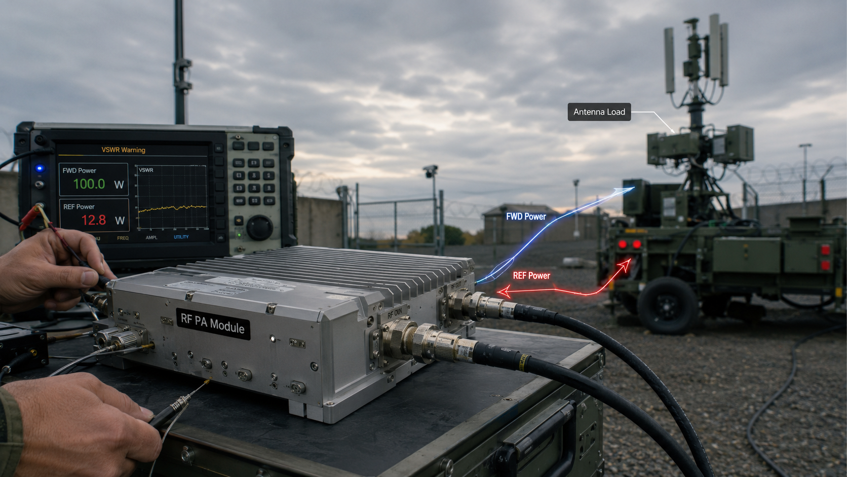
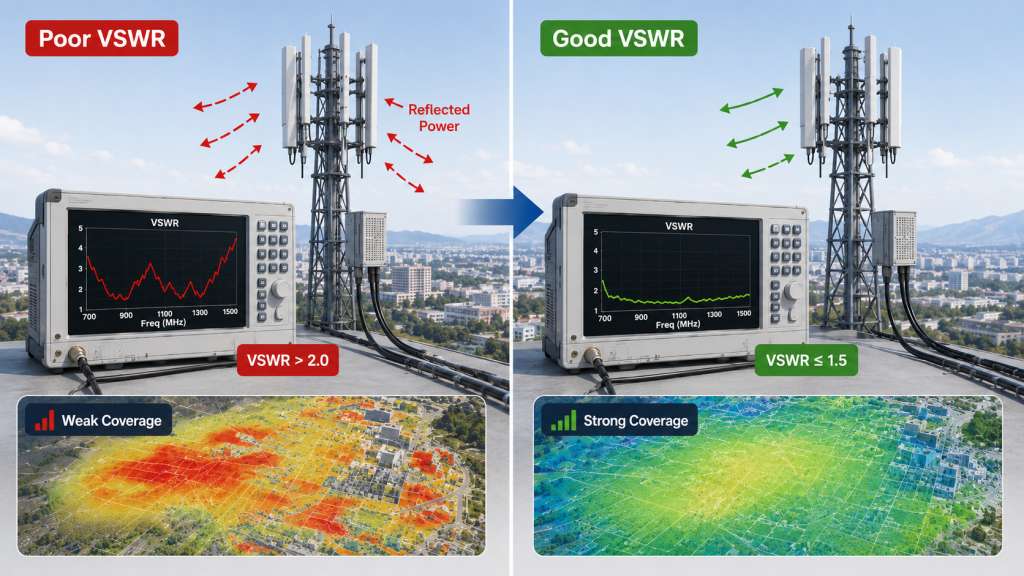
RF power amplifier field failure can happen when antenna mismatch sends reflected power back into the output stage, even if the module performs well on a 50Ω dummy load. In real counter-UAS, communication, and RF suppression systems, this failure often appears as weak coverage, rising temperature, VSWR alarms, output shutdown, or unstable long-duty operation.
Here’s the deal: you may not have a weak amplifier. You may have a bad RF load, poor antenna matching, loose connectors, cable loss, or an installation environment that detunes the antenna after final assembly. This article explains how antenna mismatch causes RF Power Amplifier failure, how VSWR protection responds, and how you can prevent reflected-power problems before field acceptance.
1. What Is VSWR in an RF Power Amplifier System?
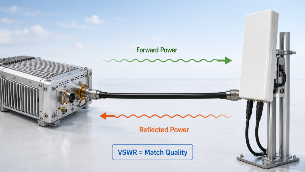
RF Power Amplifier VSWR shows how well output energy transfers from amplifier output into the connected RF load.
In practical terms, VSWR tells you whether RF energy moves cleanly through cable and antenna or bounces back toward the module. In an ideal chain, forward power leaves output stage, travels through feeder, and becomes radiated energy. In a real chain, antenna tuning, connector quality, cable behavior, and installation geometry decide how much power actually reaches air.
What does VSWR really tell you?
VSWR tells you load matching quality, not just amplifier quality. What’s the real story? A low VSWR usually means less energy returns toward output stage, while high VSWR points toward mismatch somewhere after amplifier output.
● Forward power means RF energy moving from module toward load
● Reflected power means RF energy returning from load
● VSWR describes mismatch severity
● Return loss describes reflection in another way
● Load mismatch means connected RF path does not match amplifier output
| Concept | Practical Meaning |
|---|---|
| Forward power | Power leaving amplifier output |
| Reflected power | Power returning from antenna path |
| VSWR | Matching condition indicator |
| Return loss | Reflection expressed differently |
| Load mismatch | Output load not close enough to expected impedance |
This table matters because field teams rarely fail from formulas alone; they fail when reflected power becomes heat, alarms, and lost coverage.
Why should you care beyond formulas?
You should care because a perfect bench result can become a weak field result after real antenna connection. Here’s the catch: VSWR problems may hide during early module testing if you only use a 50Ω dummy load.
● Dummy loads create controlled conditions
● Real antennas shift with environment
● Metal structures can detune radiation elements
● Loose connectors can change load behavior
● Wideband paths can behave differently across frequency
Key Takeaway: VSWR gives you an early warning about whether your RF energy can leave the system safely. For buyers and integrators, it helps separate real radiated performance from clean laboratory numbers.
2. Why Does Antenna Mismatch Happen in Real RF Systems?
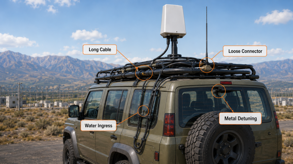
RF Power Amplifier antenna mismatch happens because real RF systems include antennas, cables, connectors, adapters, filters, combiners, and mounting structures that all affect load behavior.
Antenna mismatch often begins when amplifier frequency coverage does not line up with antenna frequency behavior. A broadband module may cover a large band, but antenna match can still degrade near edges or after installation. This makes mismatch a system-level problem, not a single-component problem.
Where does mismatch usually start?
Mismatch usually starts where hardware selection meets field installation. You might be wondering: if antenna datasheet looks correct, why does reflected power still rise?
● Antenna only matches well near center frequency
● Amplifier covers wider range than antenna
● Long feeder changes loss and phase behavior
● Connector gets loose, wet, or oxidized
● Metal vehicle roof changes antenna tuning
● Combiner or filter adds mismatch
| Mismatch Source | Field Effect |
|---|---|
| Narrow antenna match | Higher VSWR at band edge |
| Long cable | Loss and phase shift |
| Loose connector | Intermittent reflected power |
| Water ingress | Corrosion and unstable load |
| Metal structure | Antenna detuning |
| Poor adapter | Extra insertion loss and mismatch |
This comparison shows why checking only one component can miss real failure causes.
Why is this a system-level issue?
It is a system-level issue because each RF part changes what amplifier output stage “sees.” This is where it gets interesting: even a strong module can behave poorly when downstream RF path creates a difficult load.
● Vehicle body can reshape antenna environment
● Tower brackets can shift radiation behavior
● Outdoor humidity can affect connectors
● Multi-band layouts can create cable confusion
● Wideband combiners add more RF interfaces
Key Takeaway: You should treat mismatch as a full-chain engineering problem. A good antenna choice helps, but final testing after installation matters more than catalog confidence.
3. How Does Reflected Power Damage RF Power Amplifier Modules?
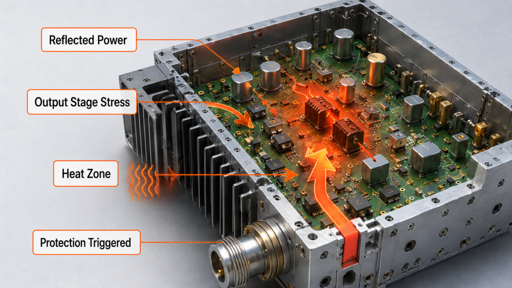
RF Power Amplifier modules can be damaged when reflected power returns into output stage and increases electrical, thermal, and matching-network stress.
Reflected power does not simply disappear. It can increase voltage and current stress at output transistor, heat matching components, and force protection logic to act repeatedly. Under severe mismatch, damage can appear as device failure, solder fatigue, overheated capacitors, degraded output, or unstable operation during continuous-duty missions.
What happens inside output stage?
Inside output stage, reflected energy changes normal operating stress. Here’s the problem: the module may still transmit for a while, but internal parts carry extra burden.
● Output transistor sees higher stress
● Matching network can heat faster
● Capacitors and inductors may run hotter
● Solder joints face thermal cycling
● Protection logic may trigger repeatedly
| Reflected Power Level | Possible Result |
|---|---|
| Slight mismatch | Lower efficiency and mild heat rise |
| Moderate mismatch | Unstable output and power back-off |
| Severe mismatch | Alarm, shutdown, or coverage break |
| Long-term mismatch | Aging and reliability loss |
| Extreme mismatch | Output-stage damage |
This risk ladder helps engineers judge why “still working” does not always mean “safe.”
Why does long-term mismatch matter?
Long-term mismatch matters because repeated stress can age components before a visible failure appears. Ready for the good part? early VSWR checks often cost far less than replacing failed modules after deployment.
● Heat cycles weaken solder interfaces
● Protection events interrupt mission continuity
● Power delivery becomes less predictable
● Field teams lose trust in coverage
● Maintenance cost rises silently
Key Takeaway: Reflected power damage can start as small instability and end as hardware failure. You protect both coverage and hardware life by finding mismatch before long-duty operation.
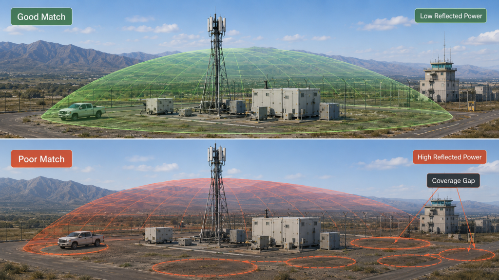
4. How Does VSWR Affect RF Power Amplifier Coverage?
RF Power Amplifier coverage becomes weaker and less consistent when high VSWR prevents forward power from reaching antenna efficiently.
Good bench output does not always mean good radiated performance. A module may meet output power targets on a dummy load, yet lose effective coverage when connected to a real antenna with poor match at certain frequencies. For counter-UAS or perimeter systems, that difference can create blind spots where you expected strong RF presence.
Why can bench power mislead you?
Bench power can mislead you because dummy-load testing removes antenna behavior from the equation. What’s the catch? real coverage depends on delivered power, antenna pattern, cable loss, and installed match.
● 50Ω load can show stable amplifier output
● Real antenna may reflect power back
● Cable loss reduces delivered energy
● Band-edge mismatch can weaken coverage
● Installation position can distort pattern
| Test Condition | What It Shows | What It May Hide |
|---|---|---|
| Dummy load | Module baseline output | Antenna mismatch |
| Lab antenna | Controlled radiation behavior | Vehicle detuning |
| Installed antenna | Real load condition | Harder troubleshooting |
| Long-duty field test | Thermal and RF stability | Requires more time |
This breakdown shows why field acceptance should include actual RF path validation.
How does uneven matching affect missions?
Uneven matching affects missions because some frequencies radiate well while others underperform. Here’s the field reality: broadband coverage can look complete in theory but behave unevenly under real load.
● One frequency point may transmit strongly
● Another point may trigger reflected-power alarm
● Coverage may shrink at band edge
● Control software may report repeated faults
● Operators may misread issue as weak amplifier
Key Takeaway: VSWR problems convert strong amplifier specs into uneven field coverage. You should validate delivered RF performance, not only amplifier output on a clean bench.
5. Why Do Wideband RF Power Amplifiers Face More VSWR Risk?
RF Power Amplifier wideband designs face more VSWR risk because antenna matching becomes harder as frequency coverage expands.
A wideband amplifier may support large frequency coverage, but antenna systems rarely maintain equally low VSWR across every point. For example, lower bands may behave differently from 2.4 GHz, 5.2 GHz, and 5.8 GHz paths. Wider coverage means more points where cable, antenna, combiner, or mounting geometry can create reflected power.
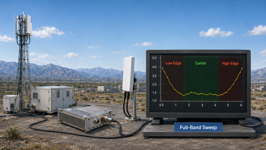
Why does wider bandwidth increase mismatch risk?
Wider bandwidth increases mismatch risk because no antenna behaves perfectly across all frequencies. This is where it gets practical: band edges often reveal problems that center-frequency tests miss.
● 300–1200 MHz systems may vary across low and high ends
● 2000–6000 MHz systems include several different RF behaviors
● Wideband antennas may trade gain for coverage
● Combiners add extra interfaces
● Multi-antenna systems create consistency challenges
| Wideband Area | Typical VSWR Concern |
|---|---|
| Low-frequency edge | Larger antenna size challenge |
| Mid-band region | Better match but still installation-sensitive |
| High-frequency edge | Connector and cable quality matters more |
| Multi-band combiner | Added reflection points |
| Vehicle installation | Detuning from nearby metal |
This chart-style table should be turned into one of your article images because it visually explains why wideband VSWR must be swept across full band.
Why must every frequency point be checked?
Every frequency point must be checked because one clean frequency cannot prove full-band stability. Here’s the deal: wideband RF failures often appear only after real sweeping, not single-point testing.
● Test low, middle, and high frequencies
● Check reflected power under real antenna load
● Compare dummy load result with installed result
● Watch protection behavior during sweep
● Repeat after final mechanical installation
Key Takeaway: Wideband systems need full-band VSWR validation. The wider the RF path, the more carefully you should check reflected power across the complete operating range.
6. What Does VSWR Protection Do in an RF Power Amplifier?
RF Power Amplifier VSWR protection detects abnormal reflected power and reduces risk by triggering alarm, power back-off, shutdown, recovery, or fault lock logic.
VSWR protection usually compares forward power and reflected power to judge load condition. If reflected power crosses a safe threshold, module logic can warn system controller, reduce RF output, shut down output stage, or recover after load returns to normal. This protection helps prevent output-stage stress from becoming a permanent failure.
What protection actions can happen?
Protection actions depend on module design and system logic. You might be asking: does protection mean amplifier can ignore any bad antenna? No. Protection reduces risk, but it cannot make a poor load become a good load.
● Reflected power detection finds abnormal return energy
● Alarm signal warns controller
● Power back-off reduces output-stage pressure
● RF shutdown stops severe stress
● Auto recovery restores output after safe condition
● Fault latch prevents repeated impact cycles
| Protection Action | Purpose |
|---|---|
| Reflected power detection | Identify abnormal RF return |
| Alarm output | Notify system controller |
| Power back-off | Reduce output-stage stress |
| RF shutdown | Stop severe mismatch damage |
| Auto recovery | Resume after condition improves |
| Fault latch | Avoid repeated fault cycling |
This table helps buyers ask for real protection logic instead of vague “protected” claims.
Why is protection not enough alone?
Protection alone is not enough because it acts after mismatch appears. Here’s the engineering truth: protection should support good RF design, not replace antenna matching.
● A poor antenna can still reduce coverage
● Repeated alarms interrupt operation
● Shutdown prevents damage but stops mission output
● Recovery logic must match system needs
● Fault data should feed controller decisions
Key Takeaway: VSWR protection gives amplifier hardware a defensive layer. You still need correct antenna selection, clean connectors, field testing, and system-level monitoring.
7. How Should You Test VSWR Before RF Power Amplifier Deployment?
RF Power Amplifier VSWR testing should happen before field acceptance, not after a module fails.
Deployment testing should include both module baseline output and full RF path validation. Start with a rated 50Ω dummy load to confirm amplifier behavior, then measure antenna VSWR curve, feeder loss, connector condition, and reflected power under real installation. Long-duty operation should also be checked because heat, vibration, and outdoor exposure can change system behavior.
What should your test checklist include?
Your checklist should cover amplifier, antenna, cable, connector, installation, and control response. Ready for the useful part? a structured checklist prevents blame games between module supplier and system integrator.
● Test amplifier on 50Ω dummy load
● Measure antenna VSWR curve
● Check feeder and connector loss
● Test low, center, and high frequencies
● Re-test after vehicle or tower installation
● Monitor reflected power during continuous output
● Confirm alarm and recovery logic
| Test Item | Why It Matters |
|---|---|
| Dummy load output | Confirms amplifier baseline |
| Antenna VSWR curve | Shows matching across band |
| Cable loss | Shows delivery loss |
| Connector inspection | Finds intermittent faults |
| Installed test | Reveals detuning |
| Long-duty test | Shows heat-related drift |
This test plan gives engineering teams a practical route from lab confidence to field confidence.
When should acceptance testing happen?
Acceptance testing should happen before handover, shipment approval, or final field sign-off. Here’s the field lesson: waiting until coverage fails makes troubleshooting slower and more expensive.
● Test before enclosure sealing
● Test after antenna installation
● Test after cable routing is fixed
● Test after vibration-sensitive mounting
● Test during realistic duty cycle
Key Takeaway: VSWR validation should be part of deployment workflow. You reduce failure risk when you test both controlled loads and real RF paths.
8. How Can Antenna, Cable, and Connector Choices Reduce Risk?
RF Power Amplifier mismatch risk drops when antenna frequency coverage, cable rating, connector quality, and installation environment are selected as one RF chain.
The amplifier is only as stable as the load it sees. A proper antenna should cover required frequencies, not just center points. Cables should match power level and frequency range, while connectors should resist water, vibration, oxidation, and mechanical looseness. After installation, the whole chain should be measured again because nearby metal and mounting height can change antenna behavior.
What hardware choices matter most?
Hardware choices matter because every weak interface can become a reflected-power source. Here’s the simple rule: fewer questionable transitions usually mean fewer mismatch surprises.
● Select antenna with correct frequency range
● Avoid relying only on center-frequency match
● Use rated connectors for frequency and power
● Reduce unnecessary adapters
● Control cable length and bending
● Protect outdoor connectors from water
● Re-test after vehicle or tower mounting
| RF Chain Part | Risk Reduction Method |
|---|---|
| Antenna | Match full operating band |
| Cable | Control loss and rating |
| Connector | Use proper type and sealing |
| Adapter | Reduce unnecessary transitions |
| Mounting | Re-test after installation |
| Outdoor exposure | Inspect water and corrosion |
This table gives field teams a quick inspection framework before blaming amplifier hardware.
Why does maintenance matter after deployment?
Maintenance matters because mismatch can appear after vibration, weather, corrosion, or mechanical change. What’s the real risk? a system can pass acceptance and still degrade months later.
● Check connector torque
● Inspect sealing and cable jackets
● Watch reflected-power trend
● Re-measure after antenna relocation
● Replace damaged adapters early
Key Takeaway: Better antenna, cable, and connector choices reduce VSWR risk before protection circuits ever need to act. Good RF hardware selection protects coverage and module life.
9. How Does VSWR Data Help Buyers Evaluate RF Power Amplifier Modules?
RF Power Amplifier VSWR data helps buyers evaluate whether a module can tolerate real antenna faults without unstable output or early damage.
A buyer should not accept “VSWR protected” without details. Ask what VSWR level the module tolerates, what reflected power triggers alarm, whether output backs off or shuts down, whether recovery is automatic, and whether testing covers open-load, short-load, and wideband frequency points. This protects you from attractive specs that collapse in real installation.
What questions should buyers ask?
Buyers should ask questions that reveal behavior under load fault, not only normal output. Here’s the buyer angle: the best data explains what happens after something goes wrong.
● What VSWR can the module tolerate?
● What reflected power triggers alarm?
● Does it back off or shut down?
● Can controller read alarm status?
● Does recovery happen automatically?
● Was testing done across full band?
● Were open-load and short-load cases tested?
| Buyer Question | Why It Matters |
|---|---|
| What VSWR can it tolerate? | Defines safety boundary |
| What happens after reflection rises? | Reveals protection logic |
| Is alarm signal available? | Supports integration |
| Is full-band testing done? | Checks wideband reliability |
| Can it recover automatically? | Affects mission continuity |
This buyer checklist turns protection claims into verifiable engineering requirements.
What data should appear in reports?
Reports should show forward power, reflected power, test frequency, load condition, and protection response. Here’s the practical filter: if data cannot show fault behavior, it cannot prove ruggedness.
● Forward power under normal load
● Reflected power under mismatch
● VSWR threshold or limit
● Alarm voltage or status output
● Shutdown and recovery behavior
● Frequency sweep coverage
● Test setup notes
Key Takeaway: VSWR data helps you judge whether a module can survive real integration stress. Ask for behavior, thresholds, and test conditions—not just headline wattage.
10. How Can You Prevent RF Power Amplifier Field Failure?
RF Power Amplifier chain design becomes safer when VSWR protection, antenna matching, cable selection, installation validation, and monitoring are planned from the beginning.
VSWR protection should not be treated as a last-minute safety feature. A safer RF chain begins with frequency planning, antenna selection, cable and connector rating, full-band measurement, installed-load validation, alarm integration, and long-duty monitoring. This approach helps your team build a system where amplifier, antenna, and controller behave as one RF architecture.
What design workflow should you follow?
You should follow a workflow that connects specification, hardware selection, testing, and field monitoring. Here’s the sequence that works: design for reflected-power control before power output becomes a field risk.
● Confirm amplifier frequency range
● Select antenna with matching coverage
● Check cable loss and connector rating
● Measure antenna VSWR across band
● Test forward and reflected power under real load
● Confirm alarm and shutdown behavior
● Validate after installation
● Monitor reflected power during operation
| Design Step | Engineering Purpose |
|---|---|
| Frequency confirmation | Avoid band mismatch |
| Antenna selection | Improve delivered power |
| Cable review | Reduce loss and reflection |
| VSWR measurement | Find load problems early |
| Protection validation | Confirm fault response |
| Installed testing | Verify real environment |
| Monitoring | Catch degradation over time |
This workflow turns VSWR from an afterthought into a design control point.
How should the project end with confidence?
The project should end with measured proof, not assumption. Here’s the final point: strong RF systems depend on delivered energy, not only amplifier output numbers.
● Keep test records by unit and band
● Compare dummy-load and antenna-load behavior
● Confirm controller reads fault signals
● Train field teams on reflected-power alarms
● Re-check outdoor systems periodically
Key Takeaway: A safer RF chain protects both mission coverage and amplifier hardware. When you design around VSWR from day one, you reduce downtime, protect output devices, and improve field confidence.
Final Engineering Takeaway
Antenna mismatch affects RF power amplifier modules by turning useful RF output into reflected stress. This article covered VSWR meaning, mismatch causes, reflected-power damage, wideband risk, protection logic, testing, hardware choices, buyer evaluation, and safer RF chain design.
If you are building counter-UAS, perimeter security, or electronic-warfare systems, you need more than power numbers. You need amplifier modules, antennas, and test logic that work together under real load. For project support, contact us today and discuss your RF chain with a factory team built around mission-critical counter-drone core components.
Our brand position is simple: reliable RF defense begins where measured engineering replaces guesswork.
FAQ
Can I run an RF power amplifier without checking antenna VSWR?
No, you should not run it that way in a serious deployment. An RF power amplifier may operate on a poor load for a short time, but reflected power can raise heat, reduce delivered output, trigger protection, or shorten hardware life.
What’s the best VSWR level for field deployment?
Lower is better, but acceptable value depends on frequency, power level, antenna type, and module rating. For field deployment, you should compare antenna VSWR across the full operating band instead of trusting one center-frequency value.
How do I know if reflected power is damaging my module?
You know risk is rising when reflected power increases, output drops, alarms appear, case temperature rises, or protection cycles repeatedly. Those signs suggest the amplifier is seeing a difficult load and needs RF path inspection.
Can VSWR protection fully prevent amplifier failure?
No, protection reduces risk but does not fix a bad RF path. It can trigger alarm, back-off, shutdown, or recovery, yet poor antenna matching can still weaken coverage and create repeated stress.
What’s the best way to reduce antenna mismatch risk?
The best way is full-chain validation. Match antenna frequency coverage, use rated cables and connectors, reduce adapters, protect outdoor interfaces, test VSWR across the band, and re-test after final installation.