


RF Power Amplifier gain flatness means how steadily an amplifier keeps gain across its full working frequency range. A wide frequency range does not automatically mean wideband performance. You may see a module marked 300–1200MHz and 100W, then assume every point from low band through high band can deliver similar behavior. Here’s the deal: that assumption can create weak output points, difficult calibration, unstable acceptance results, and late redesign pressure. In authorized counter-UAS integration, you need full-band proof, not one attractive center-frequency number. A better buying process starts with verified gain curves, output power trends, VSWR behavior, thermal data, and serial-number-based test records from an RF Power Amplifier source factory.
1.What RF Power Amplifier Gain Flatness Really Shows
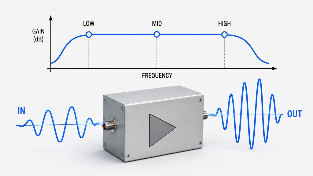
RF Power Amplifier gain flatness tells you whether gain stays stable across a specified operating band. If a 300–1200MHz module has strong gain at 900MHz but drops sharply near 300MHz or 1200MHz, its frequency label may still look wide while real full-band consistency remains weak. What’s the real story? Frequency range tells you where an amplifier can operate, while gain flatness tells you how evenly it operates.
Why Does Gain Flatness Matter in Simple Terms?
Gain flatness matters because your system does not use a datasheet number; it uses real RF output at many frequency points. A buyer, integrator, or RF engineer should treat gain flatness as a stability check across a band, not as a decorative lab value.
- Gain shows how much input signal gets amplified.
- Gain ripple shows small rises and falls across frequency.
- Band edge drop shows weakening near low or high edges.
- Full-band consistency shows whether behavior stays predictable.
Key Takeaway: You can use gain flatness as an early screening tool before spending time on deeper system tests.
| Term | What It Means | Buyer Use |
|---|---|---|
| Gain | Amplification level | Checks signal chain strength |
| Gain flatness | Gain stability across band | Checks full-band consistency |
| Gain ripple | Curve variation | Predicts tuning difficulty |
| Band edge drop | Weakness at band ends | Finds hidden risk |
This table gives buyers a simple vocabulary before discussing test reports with suppliers.
2.Why Does RF Power Amplifier Gain Flatness Come After Frequency Range?
RF Power Amplifier gain flatness comes after frequency range because you must know where the module should work before judging how evenly it works. Frequency range answers “where,” but gain flatness answers “how evenly.” Here’s the catch: a wide range printed on a label only defines possible operation, not equal performance across every useful point.
How Should You Read Frequency Range Before Flatness?
You should read frequency range as a boundary, not a guarantee of equal output. After that, you should compare gain behavior at low, middle, and high points inside that boundary.
- Confirm required operating band.
- Ask for gain data across that band.
- Compare low, center, and high frequencies.
- Check whether output power follows gain behavior.
Key Takeaway: You can avoid a false wideband assumption by treating frequency range as step one and flatness as step two.
| Selection Step | Question to Ask | Risk If Skipped |
|---|---|---|
| Frequency range | Does it cover my band? | Wrong module class |
| Gain flatness | Does gain stay even? | Uneven RF behavior |
| Output trend | Does power remain usable? | Weak field points |
| Thermal test | Does output hold over time? | Duty-cycle failure |
This sequence keeps your RF review practical instead of relying on one datasheet headline.
3.Why Can One-Point RF Power Amplifier Data Mislead Buyers?
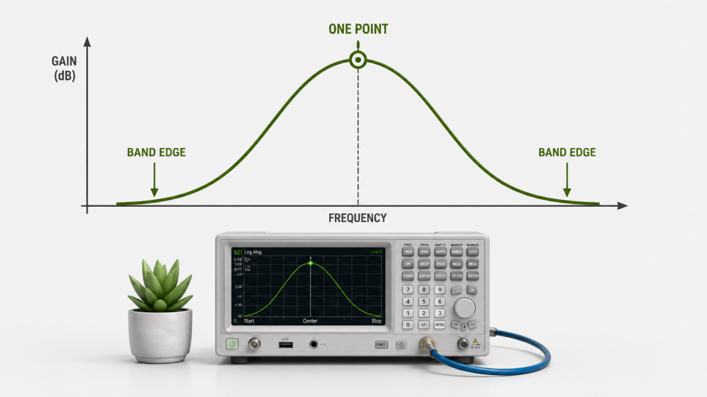
RF Power Amplifier one-point data can mislead buyers because a strong result at one frequency does not represent an entire working band. A supplier may show 900MHz, 100W, and 50dB gain, then describe the module as 300–1200MHz 100W. This is where it gets serious: 300MHz may be weaker, 500MHz may be moderate, and 1200MHz may drop again.
What Should You Ask When a Supplier Shows One Test Point?
You should ask how that number was measured, not only what the number says. Good RF purchasing depends on test conditions, not just attractive values.
- What frequency was tested?
- What input level was used?
- Was it CW or modulated input?
- What load condition was applied?
- What ambient temperature was used?
- Was data measured across full band?
Key Takeaway: You can protect your project by asking for curves instead of trusting a single beautiful data point.
| Supplier Claim | Missing Question | Buyer Risk |
|---|---|---|
| 100W output | At which frequency? | Hidden weak zones |
| 50dB gain | Across full band? | Calibration surprise |
| Wideband module | With what flatness? | Uneven performance |
| Factory tested | What test method? | Weak traceability |
A single number may start a conversation, but it should never close a technical decision.
4.What Is the Difference Between RF Power Amplifier Gain Flatness and Output Flatness?
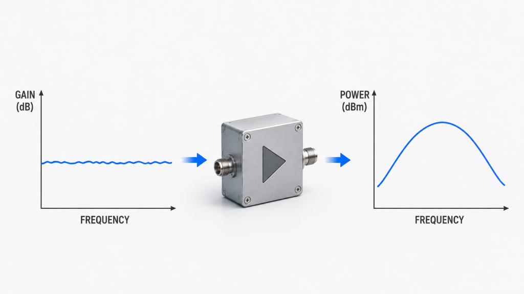
RF Power Amplifier gain flatness measures how stable amplification remains across frequency, while output power flatness measures how even final RF power remains across frequency. They relate closely, but they are not the same. You might be wondering: why check both? Because stable gain does not always prove stable final output under real drive, load, and heat conditions.
How Do Gain and Output Power Behave Together?
Gain affects output, but output also depends on drive level, compression, efficiency, matching, and protection behavior. A system may compensate some gain variation through control logic, yet that compensation can increase heat or stress.
- Gain flatness affects link budget.
- Output flatness affects coverage consistency.
- Efficiency curve affects heat load.
- VSWR behavior affects safety margin.
- Temperature trend affects long-duty stability.
Key Takeaway: You should review gain flatness and output power flatness together before approving a wideband module.
| Parameter | What It Shows | Why It Matters |
|---|---|---|
| Gain flatness | Amplification consistency | Predicts tuning effort |
| Output flatness | Final power consistency | Predicts coverage uniformity |
| Efficiency curve | DC-to-RF behavior | Predicts heat load |
| VSWR trend | Match safety | Predicts protection risk |
Poor gain flatness often warns buyers that deeper output and thermal checks may reveal more issues.
5.What Makes RF Power Amplifier Gain Flatness Hard in Wideband Modules
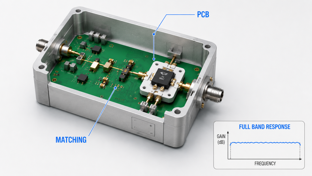
RF Power Amplifier modules with wider bandwidth need stricter flatness control because frequency response becomes harder to manage as band coverage expands. A narrowband module can focus matching around a smaller area, while a wideband module must balance transistor behavior, PCB layout, matching networks, and thermal paths across many frequency points. Here’s the deal: wider labels require stronger proof.
What Makes Wideband Flatness Harder?
Wideband design creates more places for variation to appear. The wider the band, the more every component choice matters.
- Transistors respond differently across frequency.
- Matching networks cannot favor only one point.
- PCB parasitics become more visible.
- Capacitors and inductors shift behavior by frequency.
- Antenna and load conditions become harder to balance.
Key Takeaway: You should expect stricter test evidence for wideband modules such as 30–512MHz, 300–1200MHz, 300–1700MHz, 300–2700MHz, or 2000–6000MHz.
| Wideband Challenge | Practical Effect | Needed Proof |
|---|---|---|
| Matching compromise | Gain variation | VNA gain curve |
| PCB parasitics | Ripple or loss | Full-band sweep |
| Efficiency variation | Heat difference | Thermal run data |
| Load sensitivity | Output change | VSWR test |
The wider the amplifier band, the more valuable factory-level full-band validation becomes.
6.How to Prevent Weak Zones with RF Power Amplifier Gain Flatness
RF Power Amplifier gain flatness can create weak zones when some frequency points receive less gain and produce lower final output inside an approved test band. In authorized counter-UAS integration, engineers may evaluate multiple RF chains for control, telemetry, video, navigation-related planning, and regional band differences. What’s the real story? One strong center frequency does not prevent edge-band weakness.
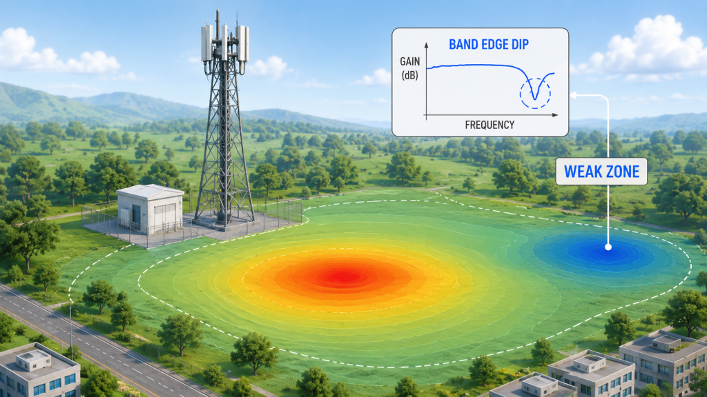
Where Do Weak Zones Usually Appear?
Weak zones often appear near band edges, transition areas, or points where matching and efficiency fall together. You may not see these problems during a quick center-frequency test.
- Low-band points may show reduced gain.
- High-band points may lose output power.
- Mid-band peaks may hide edge weakness.
- Ripple may complicate power balancing.
- Uneven output may affect acceptance checks.
Key Takeaway: You can reduce field uncertainty by reviewing flatness before integration, not after deployment testing begins.
| Flatness Issue | Possible Result | Integration Impact |
|---|---|---|
| Low-band drop | Weak low-frequency output | Coverage imbalance |
| High-band drop | Edge-band weakness | More retesting |
| Large ripple | Unpredictable control | Longer calibration |
| Center-only strength | Misleading lab success | Field mismatch |
This section keeps the discussion within authorized system planning and buyer-side verification.
7.How Does RF Power Amplifier Gain Ripple Affect Calibration?
RF Power Amplifier gain ripple affects calibration by making identical input levels produce different output levels at different frequency points. If a control board sends the same drive level, the amplifier may output 90W at one point, 110W at another, and 70W near an edge. Here’s the tricky part: control software then carries a burden that better RF hardware could have reduced.

Why Does Ripple Increase Integration Work?
Ripple forces engineers to create more correction points, test more cases, and spend more time matching commands with real output. That can slow system delivery.
- SDR source calibration becomes more detailed.
- Swept-frequency control needs more correction.
- Multi-band power balance becomes harder.
- ALC or AGC logic may require more tuning.
- Remote power settings become less predictable.
Key Takeaway: You can reduce integration time by choosing modules with smoother gain behavior across the required band.
| Calibration Area | Effect of Ripple | Buyer Concern |
|---|---|---|
| Input drive | Uneven output response | More test points |
| SDR source | More correction data | Longer tuning |
| Power command | Less predictable output | Control mismatch |
| Acceptance test | More variation | Higher failure risk |
Better flatness gives integrators cleaner behavior before software compensation even begins.
8.How Does RF Power Amplifier Gain Flatness Connect With Linearity?
RF Power Amplifier gain flatness connects with linearity because both shape real RF output behavior, though they measure different things. Gain flatness shows frequency-response consistency, while linearity shows whether amplification remains proportional without distortion. You might be wondering: can flat gain replace linearity testing? No, but uneven gain can make signal quality harder to control.
What Happens When Flatness and Linearity Are Both Weak?
A weak combination can create confusing test results. Engineers may think they have a frequency coverage issue when compression, distortion, or drive imbalance also plays a role.
- Output may stop rising predictably with input.
- Modulated signals may distort.
- Harmonic or spurious risk may increase.
- Spectrum edges may degrade.
- Troubleshooting may take longer.
Key Takeaway: You should review flatness beside linearity, gain compression, harmonics, and spurious data for a cleaner RF quality picture.
| Check Item | What It Reveals | Why Buyers Need It |
|---|---|---|
| Gain flatness | Frequency consistency | Predicts balance |
| Linearity | Distortion behavior | Protects signal quality |
| Compression | Power headroom | Prevents overdrive |
| Spurious data | Unwanted output | Supports compliance review |
Flat gain alone does not prove clean output, but poor gain behavior often complicates every other RF quality check.
9.How Does RF Power Amplifier Gain Flatness Affect Thermal Stability?
RF Power Amplifier gain flatness affects thermal stability because different frequency points can produce different efficiency and heat loads. A point with lower efficiency may generate more heat for similar output, while a weak-gain point may require higher drive to compensate. This is where it gets interesting: gain flatness should be checked cold and under realistic duty conditions.
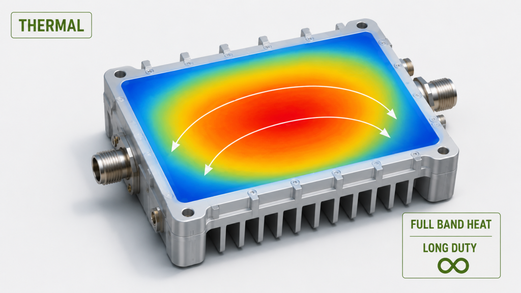
Why Should Thermal Tests Include Frequency Variation?
Thermal testing at only one frequency can miss hot points elsewhere inside the band. Long-duty operation may also change gain behavior after heat builds inside the module and enclosure.
- Efficiency varies across frequency.
- Heat can shift gain over time.
- Higher drive can raise thermal stress.
- Airflow and enclosure design affect stability.
- Derating may appear under harsh duty cycles.
Key Takeaway: You can avoid long-duty surprises by asking for gain and output behavior under realistic temperature and duty conditions.
| Thermal Factor | RF Effect | Buyer Question |
|---|---|---|
| Efficiency drop | More heat | Which points run hotter? |
| Thermal drift | Gain changes | Was it tested warm? |
| Higher drive | More stress | Was compensation needed? |
| Enclosure airflow | Cooling limit | Was setup realistic? |
A cold curve may look clean, but warm full-band behavior tells a more useful story.
10.How Can Antenna Matching and VSWR Distort RF Power Amplifier Flatness?
RF Power Amplifier flatness can be distorted by antenna matching and VSWR because module-level performance differs from full system behavior. A module may look stable on a 50-ohm lab load, yet real antennas, cables, connectors, filters, combiners, and mounting structures can reshape final output. Here’s the catch: module flatness does not automatically equal system flatness.
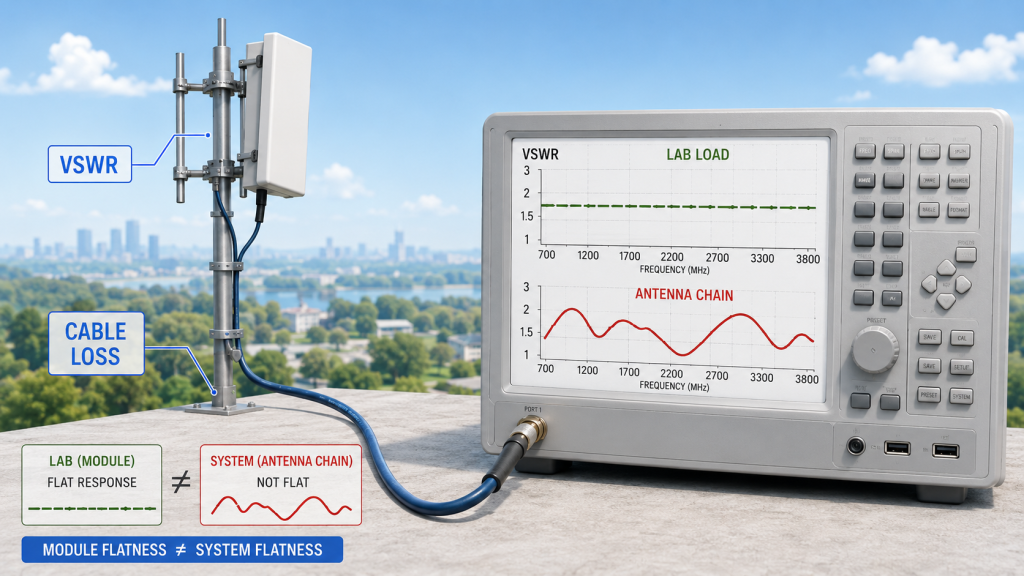
What System Parts Can Change Real Output?
Real RF systems include many frequency-sensitive parts. Each one can add loss, reflection, or ripple.
- Antenna bandwidth affects radiated behavior.
- Antenna VSWR changes by frequency.
- Cable loss rises across higher frequencies.
- Connectors and adapters add insertion loss.
- Filters and combiners shape passbands.
- Nearby metal can alter antenna response.
Key Takeaway: You should treat amplifier flatness as a foundation, then verify antenna-chain behavior before final acceptance.
| System Element | Possible Distortion | Review Method |
|---|---|---|
| Antenna | Uneven radiation | VSWR and pattern data |
| Cable | Frequency loss | Cable loss chart |
| Connector | Insertion loss | Inspection and test |
| Combiner/filter | Passband ripple | Network analysis |
A flat amplifier connected to a weak antenna chain can still create uneven field performance.
11.How to Test RF Power Amplifier Gain Flatness Before Buying
RF Power Amplifier gain flatness becomes clear through swept-frequency testing, multi-point power checks, and temperature-aware validation. Buyers do not need to become RF test engineers, but they should know what evidence separates real wideband performance from a one-point claim. Ready for the good part? Good test records make supplier conversations much easier.
Which Tests Should Buyers Request?
Buyers should request evidence that shows frequency behavior across a band, not only at one point. A source factory should understand these records and explain limits clearly.
- VNA measurement for gain curve.
- S-parameter data across band.
- Multi-point output power test.
- Full-band swept validation.
- VSWR behavior check.
- Thermal run or case temperature trend.
- Serial-number-based test report.
Key Takeaway: You can compare suppliers more fairly when each one provides the same full-band evidence.
| Test Method | What It Proves | Buyer Benefit |
|---|---|---|
| VNA gain curve | Gain versus frequency | Finds ripple |
| Multi-point power | Output at key points | Checks usable power |
| Full-band sweep | Continuous behavior | Finds hidden dips |
| Thermal run | Warm stability | Predicts duty behavior |
| S/N report | Unit traceability | Supports batch control |
Test method quality often reveals supplier capability before price negotiation starts.
12.What RF Power Amplifier Gain Flatness Data Buyers Should Request
RF Power Amplifier gain flatness data should include tolerance, curve shape, band-edge behavior, output trend, and exact test conditions. If a supplier only gives one gain number, buyers should ask how that number was measured. What’s the real story? A clear test answer often matters more than a polished sales line.
What Questions Should Go Into Your RF Buying Checklist?
Your checklist should force specific answers. General promises rarely help when integration problems appear later.
- What gain flatness tolerance applies across the band?
- Was gain measured at one point or swept?
- Are low, center, and high points tested?
- What happens at both band edges?
- Was input CW or modulated?
- What input power was used?
- What load and temperature were used?
- Does each unit receive an S/N report?
Key Takeaway: You can filter weak suppliers quickly by asking for measurement conditions, not just brochure values.
| Buyer Question | Strong Answer Should Include | Warning Sign |
|---|---|---|
| Where was gain tested? | Full-band curve | One point only |
| What about band edges? | Low/high data | No edge data |
| What conditions? | Input, load, temp | Vague response |
| Unit traceability? | S/N report | Batch uncertainty |
A supplier that cannot explain the curve may not fully understand the module behind the quote.
13.Why Does Source Factory Validation Matter for RF Power Amplifier Gain Flatness?
RF Power Amplifier source factory validation matters because gain flatness depends on design, materials, assembly, housing, thermal path, and testing, not only final inspection. A trader may repeat a parameter, but a factory engineering team can explain why one frequency drops, why a batch differs, or why a load condition changes behavior. Here’s the deal: flatness comes from controlled engineering, not sales wording.

What Can a Source Factory Control Better?
A source factory can connect design feedback with production data. That makes root-cause analysis faster when buyers ask technical questions.
- Transistor selection and matching network design.
- PCB layout and grounding.
- BOM consistency and golden sample control.
- CNC housing, shielding, and thermal contact.
- Full-band sweep procedure.
- Batch comparison and engineering feedback.
- Custom frequency and output validation.
Key Takeaway: You can reduce batch risk by working with a supplier that controls design, manufacturing, and RF validation under one engineering loop.
| Factory Control Point | Flatness Impact | Buyer Value |
|---|---|---|
| BOM lock | Reduces batch drift | Stable repeat orders |
| Matching design | Smooths response | Better consistency |
| CNC housing | Improves grounding and heat | Stronger stability |
| Full-band test | Finds weak points | Clear acceptance data |
For professional RF procurement, factory validation turns a parameter into accountable evidence.
14.How to Choose Modules Using RF Power Amplifier Gain Flatness
RF Power Amplifier selection using gain flatness should follow a practical verification sequence: confirm range, request curves, compare band points, review output power, check antenna-chain risk, and verify thermal behavior. Ready for the useful part? This process helps you move from datasheet reading into real integration confidence.

What Step-by-Step Selection Flow Works Best?
A simple flow can keep both purchasing and engineering aligned. You do not need to reject every module with variation, but you do need to understand variation before approval.
- Confirm required frequency range.
- Ask for gain curve across full band.
- Compare low, center, and high points.
- Check output power flatness.
- Review efficiency and thermal behavior.
- Check VSWR and antenna matching.
- Request serial-number-based data.
- Choose direct engineering support.
Key Takeaway: You can choose more confidently when a supplier proves wideband behavior across frequency, load, and duty conditions.
| Selection Step | Evidence Needed | Decision Value |
|---|---|---|
| Range match | Frequency specification | Confirms coverage |
| Gain curve | VNA sweep | Confirms consistency |
| Output trend | Power data | Confirms usable RF |
| Thermal review | Duty test | Confirms stability |
| Supplier review | Engineering support | Confirms accountability |
Gain flatness is not a small lab detail; it is a practical signal of predictable wideband performance.
15.Final Buying Guidance for RF Power Amplifier Gain Flatness
RF Power Amplifier gain flatness helps buyers solve one costly question: does a wide frequency label prove usable wideband performance? The answer is no unless the supplier can support that label with full-band evidence. This article showed why one-point data can mislead buyers, how gain flatness differs from output flatness, why ripple affects calibration, how heat and VSWR change real behavior, and what data you should ask for before approval.
If you are building authorized counter-UAS, RF communication, or wideband integration systems, you need more than a broad frequency range. You need stable gain behavior, traceable output records, thermal confidence, antenna-chain awareness, and direct engineering answers. For application-specific module review, custom frequency planning, or source-factory RF validation, contact us today. Our brand position is simple: predictable RF performance should be proven across the band, not promised at one easy point.
FAQ
Can I judge an RF amplifier only by frequency range?
No, frequency range alone is not enough. It tells you where the amplifier may operate, but it does not show whether gain, output power, efficiency, and heat remain stable across that band. You should ask for gain flatness and output trend data before making a serious buying decision.
What’s the best way to check gain flatness before buying?
The best way is to request a full-band gain curve. You should also ask for low, center, and high frequency output power data, test conditions, load condition, and temperature information. A serial-number-based report gives stronger traceability for each delivered unit.
How do I know if one-point power data is misleading?
You know it may be misleading when the supplier gives only one frequency, one output value, or one gain number without explaining test conditions. A 900MHz result cannot represent a 300–1200MHz module unless full-band behavior is also shown. Ask for curve data and band-edge results.
Can I accept some gain variation across a wideband module?
Yes, some variation is normal in wideband RF design. The real question is whether variation stays within your system tolerance and whether output power, thermal behavior, and VSWR remain acceptable. You should judge variation against integration needs, not against a perfect flat line.
What’s the best supplier type for gain flatness validation?
A source factory with RF engineering, manufacturing control, and full-band test capability is usually the stronger choice. Gain flatness depends on design, BOM consistency, PCB layout, housing, thermal path, and test process. Direct engineering support helps you solve problems faster when data looks uneven.