











Choose an RF PA frequency range from the project-approved frequency points or windows and their operating relationship before comparing output power. A listed range is an initial screening boundary, not proof of equal output, gain, thermal margin, or load behavior at every required point.
The widest catalog label is not automatically the safest choice. Extra span can add filtering, path, thermal, and verification demands without improving the project result. The better starting point is a coverage and architecture combination that fits the approved requirement without avoidable frequency span.
The shortlist remains conditional on the defined output reference plane and on the project’s signal, RF-path, supply, thermal, and evidence boundaries. If a decision-critical input is missing, keep the result at candidate level and complete the requirement set first. All operating requirements must follow the customer’s lawful authority, applicable spectrum rules, and approved deployment plan.
1.What an RF PA Frequency Range Can—and Cannot—Tell You
A published frequency range shows where a module or product family may be considered for initial review. It does not, by itself, establish a project-qualified operating range.
Keep three meanings separate:
- Listed or nominal range: the published boundary used for initial screening.
- Candidate range: a range that contains the approved project points or windows and remains plausible after the first architecture review.
- Project-qualified range: the frequencies that meet the project’s defined requirements and acceptance criteria under the applicable operating and evidence conditions.
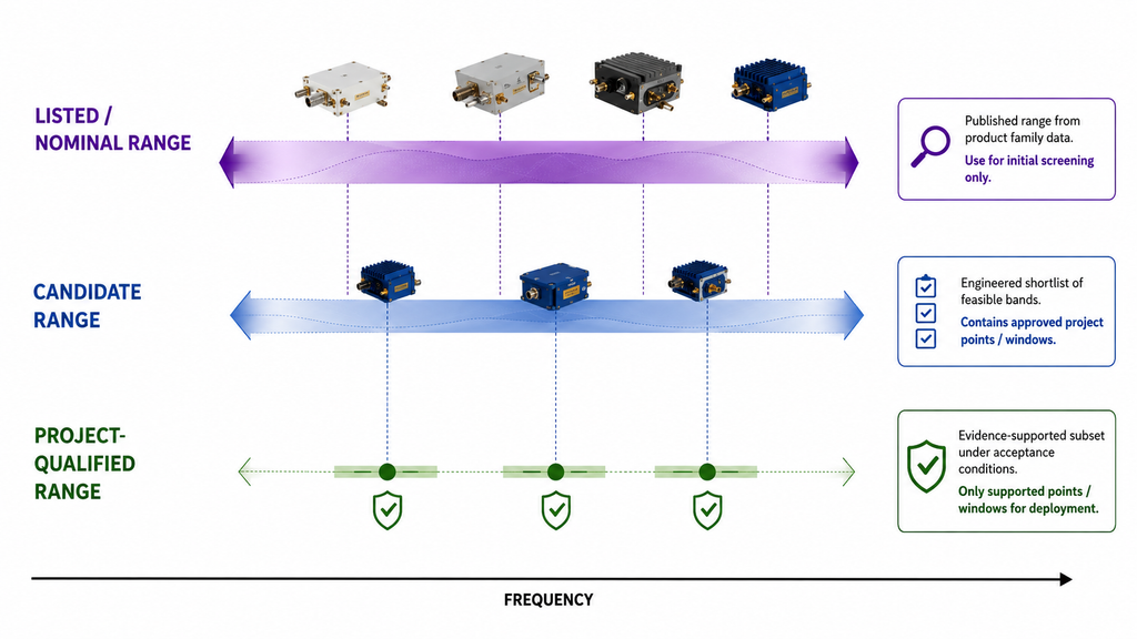
Performance can vary across frequency. A result at one convenient point does not establish the same output, gain, efficiency, thermal behavior, or mismatch response elsewhere in the range. Unless a document explicitly defines system-level conditions, a published module range also does not establish performance after cable, connector, filter, switch, antenna, enclosure, or cooling effects are added.
Use the listed range to build a shortlist. Treat a project-qualified range as a later engineering conclusion supported by applicable evidence at the required points and conditions.
2.Why Frequency Comes Before Output Power
Output power is useful only at the frequencies the system is authorized and designed to use. A higher power rating in the wrong range is not a stronger solution; it is a mismatch between the module and the project requirement.
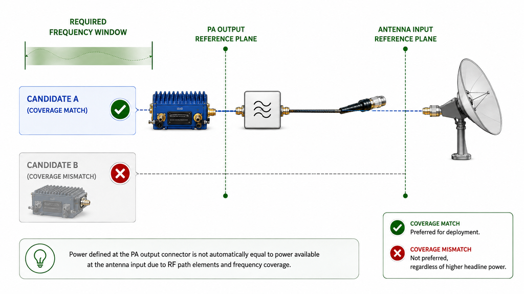
Power must also be tied to a reference plane. A requirement at the RF PA output connector is different from a requirement at the antenna input or another downstream point. Feeder, connector, switch, filter, and other RF-path losses can separate PA-port output from the power available later in the chain.
Define the approved frequency requirement and operating relationship first. Then identify the bandwidth class and RF-path topology, define output power at the correct reference plane, and compare only candidates whose relevant conditions are sufficiently aligned. This order prevents a headline power value from driving the decision before the actual coverage and system boundaries are understood.
3.Start with Project-Approved Frequency Points and Operating Relationships
Do not begin with a generic list of “common” C-UAS bands. Begin with the frequency points or windows approved for the actual project, site, system design, and lawful operating condition.
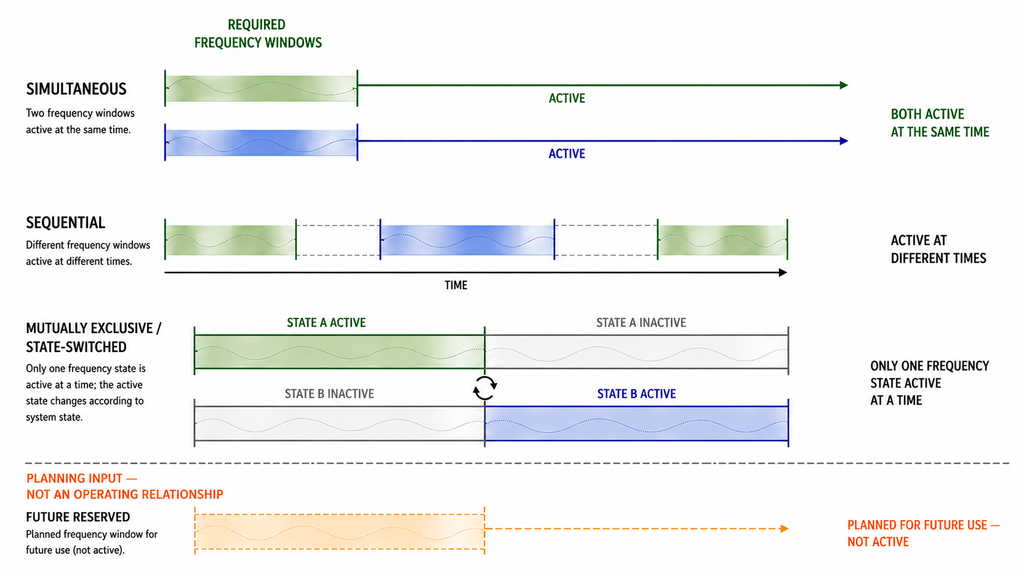
Record how the required frequencies relate in time and operating state:
- Simultaneous: more than one frequency must be active at the same time.
- Sequential: different frequencies are used at different times.
- Mutually exclusive or state-switched: only one frequency state is active at a time.
Record any fixed RF-path assignment separately. A requirement for different amplifier, filter, feeder, or antenna paths is a topology constraint, not another operating relationship.
Record future-reserved frequencies separately from current mandatory coverage. They are planning inputs, not operating relationships, and should not silently expand the present selection requirement.
Two required points can fit inside one catalog range and still need separate RF paths. Conversely, several points may be served by one path when their frequency distribution, operating relationship, filtering, switching, output, and thermal conditions allow it.
If the approved points or windows, their operating relationships, or the output reference plane are not defined, stop at requirement development. Do not approve or reject a module from the range label alone.
4.Choose the Bandwidth Class and RF-Path Architecture
Make the selection on separate axes.
First choose the bandwidth class—narrowband or wideband—from the shape of the required coverage. Then choose the RF-path topology—single, switched, segmented, or independent—from the operating relationship and any fixed path constraints. Consider custom engineering review only when suitable standard product-family candidates, evaluated in the required RF-path topology, cannot meet the defined frequency, mechanical, control, thermal, or evidence boundary.
Compare RF SKYPOWER Wideband Product Families by Required Range
If the bandwidth-class decision keeps a wideband route in the candidate set, use the table below to identify the closest published RF SKYPOWER product family for initial review. Start with the narrowest listed family that contains the current mandatory frequency points for that RF path. Do not enlarge the candidate range only to absorb undefined requirements or frequencies reserved for possible future expansion.
RF SKYPOWER Product-Family Shortlist
| Product Image | RF SKYPOWER Product Family | Published Output Classes* | Natural Shortlist Trigger | Boundary Before RFQ |
|---|---|---|---|---|
|
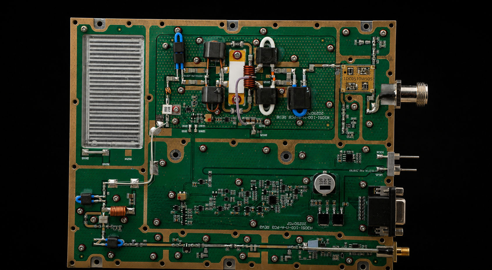
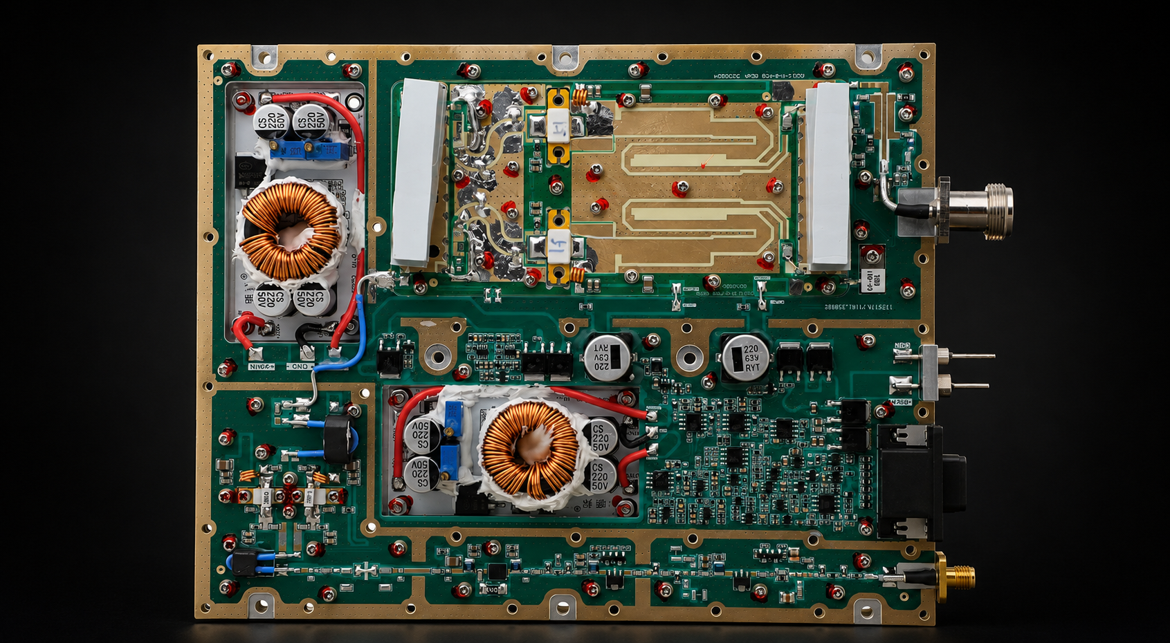
30–512 MHz Low-band RF PA Modules | 30 W, 50 W, 100 W, 150 W, 200 W | All current mandatory points for the defined RF path fall within 30–512 MHz. | Confirm the exact frequency points, actual Pin, PA-output reference plane, load condition, and cooling boundary. |
|
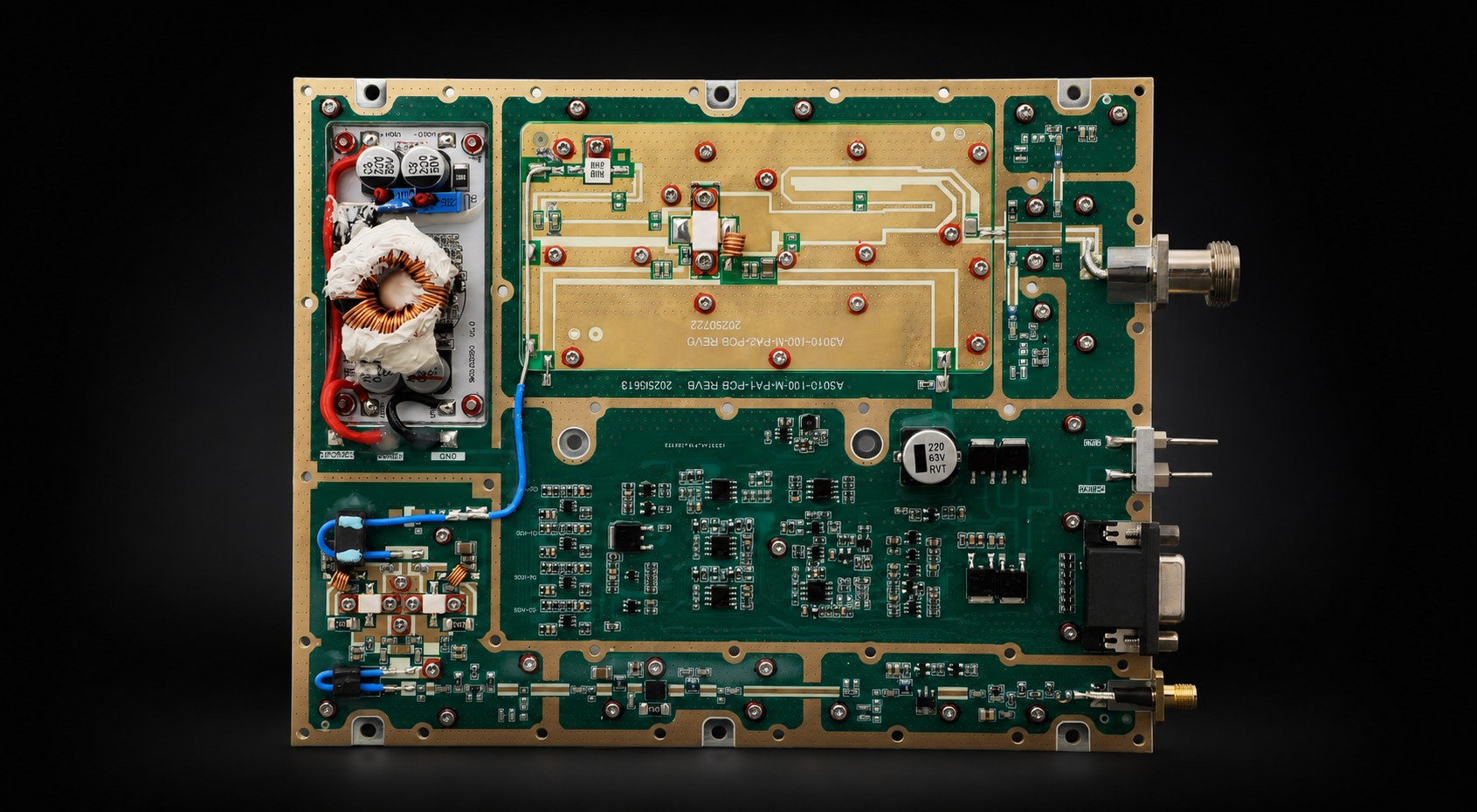
300–1200 MHz Low / mid-band RF PA Modules | 30 W, 50 W, 100 W, 150 W, 200 W | The required span extends beyond 512 MHz but remains within 1.2 GHz. | Check the project-critical points and edges; the listed span does not prove equal output across the range. |
|
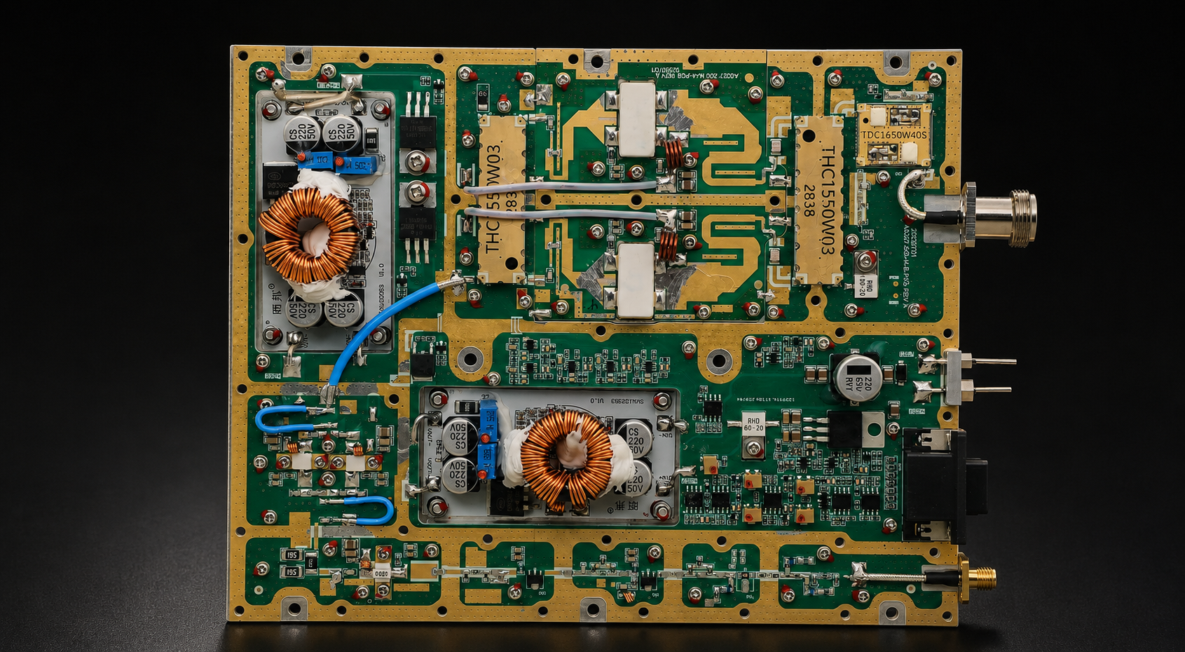
300–1700 MHz Extended mid-band RF PA Modules | 30 W, 50 W, 100 W, 150 W, 200 W | A 300–1200 MHz family is too narrow, while a 300–2700 MHz family would add unnecessary span. | Verify why the upper span is required and request applicable evidence at the project-critical upper-frequency points. |
|
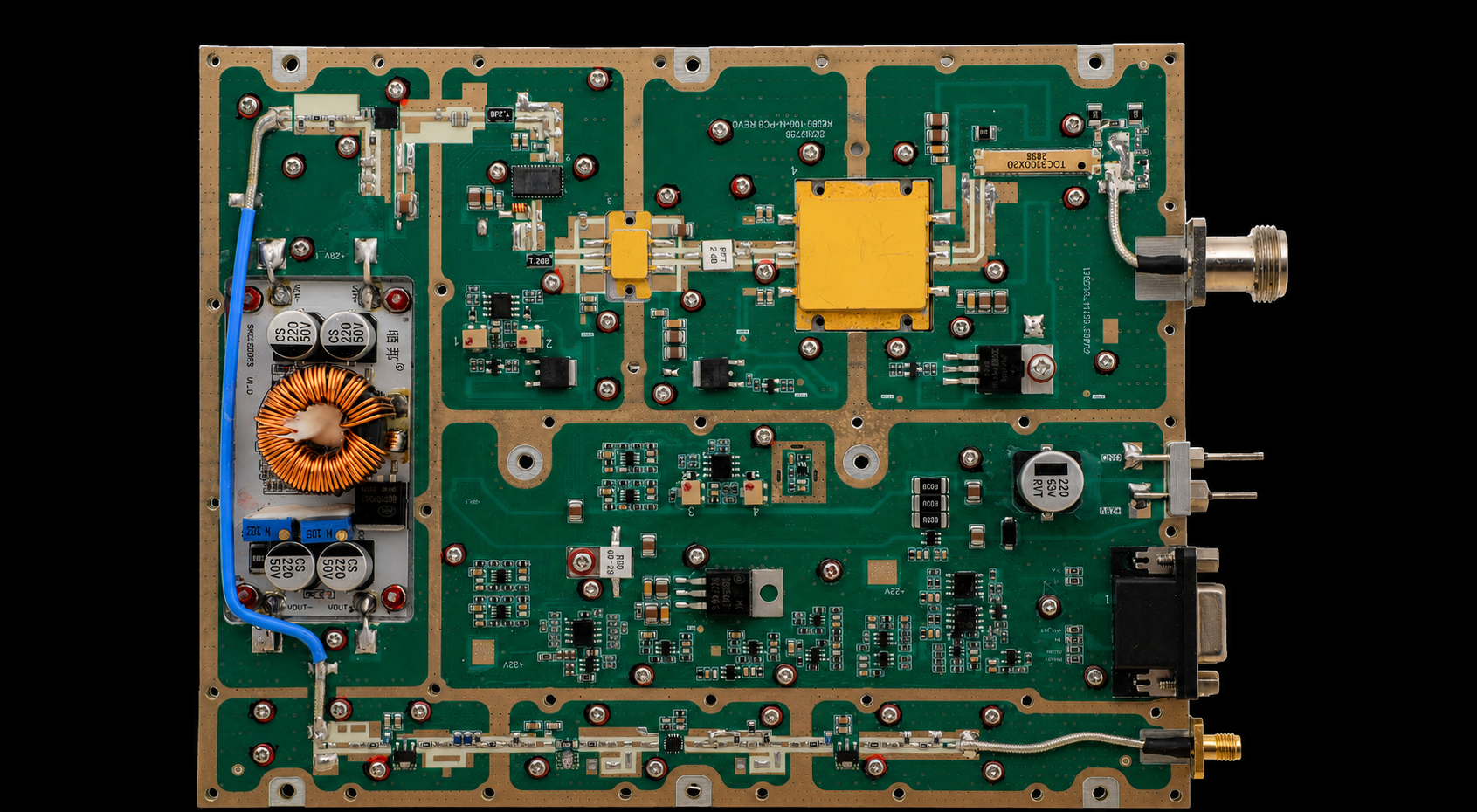
300–2700 MHz Wideband RF PA Modules | 30 W, 50 W, 100 W, 150 W, 200 W | Several mandatory points or windows extend across a broad lower-to-mid-band range. | Do not assume one wideband module or RF path is sufficient when separated windows must operate simultaneously. |
|
2000–6000 MHz Upper-band RF PA Modules | 30 W, 50 W, 100 W, 150 W, 200 W | The defined RF path requires operation within the 2–6 GHz range. | Review feeder, connector, filter, switch, and antenna-path loss together with the defined output reference plane. |
* Published output classes are product-discovery information, not confirmation of stock, final configuration, equal full-band output, or project suitability. Confirm the exact model, hardware revision, operating conditions, current availability, and evidence scope before RFQ.
A narrowband route may still be more appropriate for one fixed frequency window. Custom engineering review also remains a separate route when suitable standard product-family candidates cannot meet the defined frequency, mechanical, control, thermal, or evidence boundary. Neither route should be selected merely because the original requirement is incomplete.
This table narrows the commercial search; it does not complete model selection. The next step is to verify whether the shortlisted product family remains eligible under the project’s actual operating conditions and acceptance criteria.
5.What Must Be Verified Before the Shortlist Can Move Toward Approval
A frequency-range shortlist can move toward project approval only after the project-critical points are checked under defined conditions. These checks determine whether a candidate remains eligible for validation; they do not replace the project’s acceptance criteria.
- Operating and electrical conditions: required frequencies, waveform, occupied bandwidth where relevant, duty cycle, Actual Pin at the RF PA input reference plane, required output at the defined output reference plane, DC supply voltage at the defined PA supply terminal, available current and operating state, cooling boundary, and cold, transition, or stabilized hot-state status.
- Reference-plane and system boundary: permitted load mismatch or load-VSWR at the PA output reference plane, plus the distinction between a controlled dummy-load result and installed behavior after filter, switch, connector, feeder, and antenna effects.
- Evidence scope: applicable product family, exact model and revision where relevant, test conditions, measured or corrected status, covered points or edges, and one-unit, representative-sample, delivered-S/N, or batch scope. A datasheet supports only its published scope; an S/N-linked report supports only the identified unit under its stated conditions.
If the relevant conditions are not sufficiently aligned, the candidates are not yet comparable. Request the missing evidence or hold the decision instead of ranking them by a larger frequency span or output-power value. Sweep steps, correction methods, dwell conditions, and acceptance limits belong in the subsequent validation plan.
Build the Frequency-Range Selection Brief Before RFQ
Before requesting a quotation, convert the requirement into a short engineering brief. It should make clear what is mandatory now, what is reserved for later, what architecture is being considered, and what remains unresolved.
Frequency-Range Selection Brief
| Selection item | Project condition to record | Supplier or evidence input needed | Decision use |
|---|---|---|---|
| Required frequencies | Current mandatory points or windows; future-reserved frequencies recorded separately | Approved requirement set or frequency plan | Proceed only when current coverage is defined |
| Operating relationship | Simultaneous, sequential, mutually exclusive, or state-switched operation | System-state description | Constrains the RF-path topology |
| Bandwidth class | Narrowband or wideband starting point for each required path | Applicable product-family scope | Candidate screening only |
| RF-path topology | Single, switched, segmented, or independent path | Filter, switch, feeder, antenna, and control boundaries | Determines system architecture and review scope |
| Signal and drive | Waveform, occupied bandwidth where relevant, duty cycle, and Actual Pin at the PA input reference plane | Condition-matched performance evidence | Hold if the operating condition is materially different |
| Output and installed path | Required output and reference plane, path-loss boundary, and permitted load mismatch | Power definition and RF-path information | Not comparable if reference planes differ |
| Supply and thermal boundary | DC supply at the defined PA supply terminal, current limit, mounting, cooling method, ambient or inlet condition, and required thermal state | Electrical and thermal operating limits or applicable evidence | Verify under the intended boundary |
| Approval evidence | Datasheet and/or test report scope, model and revision, frequency coverage, correction status, unit or sample identity, and required report format | Evidence matched to the defined requirement and acceptance criteria | Use for approval only within the supported scope and project process |
The brief should lead to one of three outcomes: continue with a candidate, hold until missing inputs are defined, or request a focused engineering review. It should not force a product choice while the project boundary is incomplete.
FAQ
Can the widest RF PA frequency range be the safest choice?
Not automatically. A wider listed range may improve flexibility, but it can also require broader filtering, thermal, RF-path, and verification work. The safer candidate is the one that covers the approved requirement without unnecessary span and can be supported by applicable evidence.
When should RF PA frequency-range selection be put on hold?
Put the decision on hold when a material input—such as the approved frequencies, operating relationship, output reference plane, waveform or duty cycle, RF-path boundary, supply condition, cooling boundary, or required evidence—is undefined. Do not use a catalog range or output-power value to fill that gap.
When does a custom frequency-range review become necessary?
Custom review is an engineering route, not a bandwidth class or RF-path topology. It becomes reasonable when available standard product-family candidates, evaluated with the required bandwidth class and topology, cannot meet the defined frequency, mechanical, control, thermal, or evidence boundary. Document the exact mismatch before requesting customization.
Conclusion: A Candidate Range Is Not Yet an Approval
Choose an RF PA frequency range by defining the project-approved points or windows and their operating relationship first. Then select the bandwidth class and RF-path topology that cover the current requirement without unnecessary span. Compare output power only at a defined reference plane and under sufficiently aligned conditions.
A listed range supports screening; it does not establish project-qualified operation. The widest label is not automatically the safest choice, and a product-family match does not confirm exact-model suitability, installed-system performance, or delivered-unit evidence.
Before contacting a supplier, complete the Frequency-Range Selection Brief and mark the result as proceed, hold, or engineering review. Then use the product-family table to identify the closest published range and submit the brief so that the selected family can be reviewed under the project’s actual conditions.
To request an RF SKYPOWER engineering review, send the approved frequencies, operating relationship, output requirement and reference plane, available RF drive, waveform and duty cycle, RF-path boundary, supply and cooling limits, control requirements, and evidence needs. The review may identify a standard product-family candidate and the topology in which it should be evaluated, or it may show that a custom engineering review is needed. Final suitability still depends on applicable evidence and the project’s acceptance criteria.