










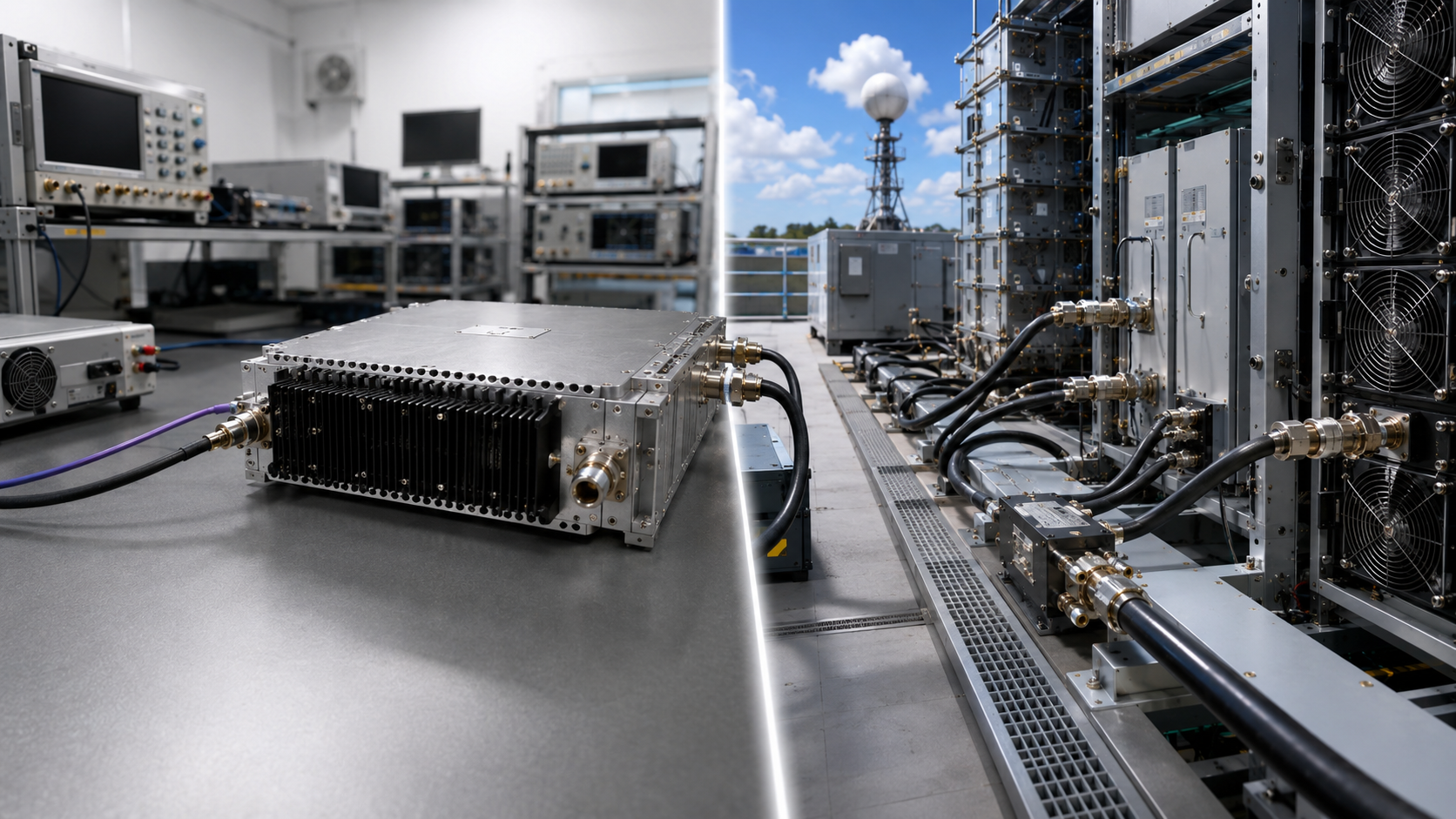
RF power amplifier reliability should not be judged from one output-power value, one datasheet rating, or one short bench result.
Before RFQ requirements are finalized, the buyer should define the operating boundary and check whether the available evidence was produced under conditions that can actually support the reliability claim.
This matters because similar headline results may come from different frequencies, input-drive levels, waveform conditions, measurement reference planes, duty cycles, temperatures, DC inputs, cooling conditions, or loads. When those differences materially affect the decision, the evidence is not yet directly comparable.
The RFQ-stage question is therefore not simply:
“Is this RF power amplifier reliable?”
A more useful question is:
“Are the requirement, operating condition, evidence, and evidence scope defined well enough to support the next engineering decision?”
1. What Must “Reliable” Mean Before an RFQ?
Before RFQ, “reliable” should describe acceptable behavior inside a defined operating boundary—not a general supplier adjective.
Depending on the application, that boundary may include:
- required RF output at specified frequency points;
- gain or gain variation;
- waveform or spectral quality where relevant;
- thermal behavior under the intended operating duty;
- DC voltage and current behavior;
- load-mismatch or reflected-power behavior;
- protection response and recovery;
- repeatability or traceability at the evidence level required by the project.
Not every project needs the same evidence.

A datasheet may define an intended rating or operating range. A laboratory result may show how a tested sample behaved under a stated condition. A unit-level report may support a delivered module when the evidence is linked to that unit.
Those evidence types are not interchangeable.
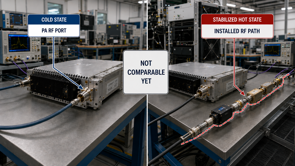
For example, evidence measured at the PA RF port does not automatically prove the complete installed path after cables, connectors, filters, switches, or antennas are added. A test on one sample also does not automatically prove production-batch consistency.
Before supplier approval, the buyer should therefore separate three questions:
- What requirement must be met?
- Under what condition was the supporting evidence produced?
- What sample, unit, batch, configuration, or system does that evidence actually represent?
If any of these are unclear and the missing information can change the decision, the reliability claim is not yet ready for approval.
2. Are the Evidence Conditions Aligned Well Enough to Compare?
Before reliability evidence is compared, confirm that the conditions which materially change the decision are defined consistently.
This page uses those conditions to judge evidence readiness. It does not attempt to turn every power, thermal, VSWR, or protection question into a complete specialist test procedure.Detailed reliable RF power comparison belongs to the separate power-claim review rather than this RFQ-stage evidence-readiness page.
Typical conditions that may need to be aligned include:
- frequency or required operating point;
- waveform and reported power metric;
- input-drive condition;
- RF measurement reference plane;
- duty cycle or test duration;
- cooling or thermal state;
- DC supply condition;
- load or reflected-power boundary;
- protection state;
- evidence scope.
The important principle is not that every project must test every condition above.
The requirement is that any condition capable of changing the engineering decision must be defined clearly enough to interpret the evidence correctly.
For example, a result measured cold should not automatically be treated as stabilized hot-state evidence when thermal loading matters. PA-port power should not be treated as installed antenna-path power when the reference plane is different. A result from one tested unit should not automatically be treated as batch evidence.
If the material conditions behind two results are different or unknown, do not convert the headline numbers into a supplier ranking.
Record the gap, align the conditions, or request the missing evidence first.
3. How Should Reliability Risks Map to Evidence?
Different reliability risks require different evidence.
RF Performance Risk
Where RF output or gain is part of the decision, the evidence should correspond to the required operating point.
Depending on the project, useful evidence may include frequency-specific Pout, Actual Pin, the defined RF amplifier input drive level, gain, gain variation, or an applicable signal-quality metric.
Small-signal data can describe part of the amplifier behavior, but it does not automatically establish performance at the required large-signal operating condition.
Thermal Risk
Thermal evidence is useful only when the operating and cooling conditions are known.
If the project creates meaningful thermal loading, the RF power amplifier duty cycle, operating duration, cooling boundary, and thermal state may all change what the evidence proves.
A short cold-state result should not be used as proof of stabilized hot-state behavior unless the two conditions are known to be equivalent for the decision being made.
DC and Power-Distribution Risk
RF amplifier power supply requirements should be evaluated together with the RF operating condition rather than as an isolated voltage value.
Supply voltage, DC cable voltage drop, current limiting, startup behavior, and power-distribution conditions can change the available electrical margin even when the RF module itself has not changed.
Where those factors affect the requirement, the evidence should identify the relevant Vdc, Idc, and operating condition.
Load and VSWR Risk
A controlled load can establish a useful PA-level baseline, but it does not automatically prove the installed RF path.
The buyer should distinguish between:
- PA behavior under a defined load or reflected-power condition; and
- behavior of the integrated RF path that may include cables, connectors, filters, switches, lightning protection, grounding, and the antenna.
The measurement reference plane determines what the result can support.
Protection Risk
RF PA protection logic should be evaluated through observable behavior rather than treated as a feature label.
If protection behavior matters to acceptance, the requirement may need to define:
- the condition being detected;
- the visible alarm or status;
- whether output changes;
- whether the PA shuts down;
- how recovery occurs;
- whether a reset is required;
- whether the required behavior is repeatable.
The actual thresholds and states must come from the applicable product or project evidence. They should not be inferred merely because a protection feature is listed.
4. When Does a Reliability Question Need a Specialist Test?
The RFQ-stage review should define what must be proven.
It does not need to reproduce every detailed test procedure.
A dedicated RF amplifier reliability test, RF amplifier VSWR test, or RF amplifier acceptance test should be selected only when that specific risk or acceptance decision requires it.
Examples include:
- Uncertain performance across required frequency points may require a swept-frequency full-power RF PA test.
- concern about cold-to-hot performance change;
- reflected-power or VSWR behavior that matters to the application;
- unclear protection detection, response, or recovery;
- long-duration or aging requirements;
- burn-in or production-consistency requirements;
- unit-level shipment evidence;
- traceability between a report and a delivered S/N;
- field behavior that differs from the known PA baseline after system integration.
The sequence should remain clear:
First define the decision requirement. Then select the test capable of producing the required evidence.
This prevents the RFQ-stage page from becoming a generic testing manual and keeps detailed test execution with the appropriate specialist procedure.
5. What Evidence Is Still Missing Before Supplier Approval?
The most useful RFQ-stage review connects five items:
Requirement → Evidence → Condition → Evidence Scope → Decision Use
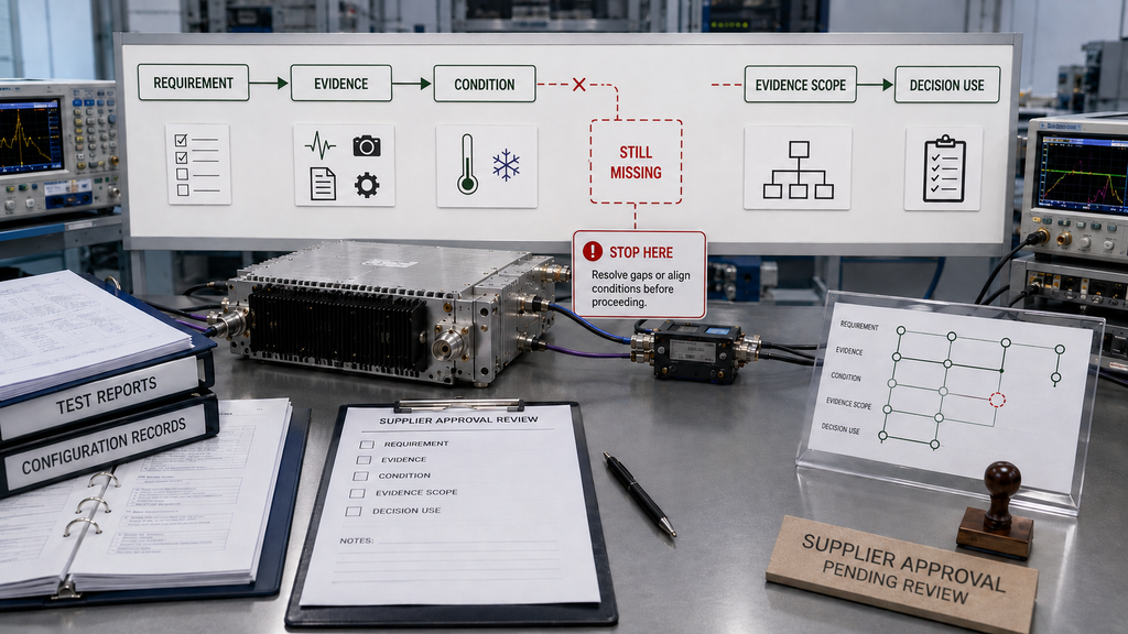
This table is an RFQ planning map rather than a shipment-release checklist. It identifies what should be defined before supplier review. For C-UAS projects, the C-UAS RF PA acceptance checklist provides the deeper shipment-release structure for per-unit, batch-level, configuration-level, and project-level evidence.
| Buyer Requirement | Evidence to Request | Required Condition | Evidence Scope | Decision Use |
|---|---|---|---|---|
| Required RF output | Frequency-specific Pout with Actual Pin where relevant | Required operating points, stated waveform or power metric, stated RF reference plane | Tested sample or unit | Determine whether the required RF operating points are supported |
| Gain consistency | Gain or gain-variation data where required | Same operating boundary used for the RF decision | Tested sample or unit | Identify unacceptable variation across the required range |
| Signal quality | Applicable compression, harmonic, ACPR, EVM, or other project metric | Required waveform and RF output condition | Tested sample or unit | Determine whether usable output meets the signal requirement |
| Thermal behavior | Relevant RF, DC, and temperature evidence | Defined duty cycle, duration, cooling boundary, and thermal state | Tested sample or unit | Determine whether thermal buildup changes the engineering decision |
| DC behavior | Vdc / Idc and applicable startup or limit information | Required supply and RF operating condition | Tested sample or unit | Check electrical margin under the intended system boundary |
| PA load / reflected-power behavior | FWD / REV / VSWR or other applicable load evidence | Defined load condition plus the stated FWD / REV / VSWR measurement reference plane | PA module under the stated load boundary | Determine how the module behaves under the defined load condition |
| Installed RF-path behavior | System-level RF / VSWR evidence where integration behavior is part of the requirement | Measurement plane includes the applicable cable, filter, switch, antenna, or other RF-path elements | Integrated system | Determine whether the installed path meets the system-level requirement |
| Protection behavior | Alarm/status, output response, shutdown, recovery, or reset evidence as applicable | Defined fault condition and operating state | Tested sample or unit | Verify the required behavior rather than relying on a feature label |
| Delivered-unit traceability | Test date, configuration/version information, and S/N-linked evidence where required | Same configuration and acceptance boundary defined for the unit | Delivered unit | Connect the evidence to the hardware being accepted |
| Repeat delivery or batch consistency | Agreed batch, sampling, or production evidence | Defined sample size, configuration, and test boundary | Batch or production lot | Support repeat-delivery decisions without treating one sample as the whole batch |
An RF amplifier test report does not become strong evidence simply because it looks formal. Its value depends on the test condition, reference plane, configuration, and the unit or batch it actually represents.
A frequency sweep on one sample does not automatically prove batch consistency.
A unit-level report does not prove the installed antenna path.
A room-temperature result does not automatically establish hot-state behavior.
A datasheet rating does not prove that a particular delivered S/N was tested to that rating.
Decision Stop
If a material condition is missing, do not convert incomplete evidence into a supplier ranking.
The appropriate action is to:
- record the evidence gap;
- request the missing condition or result;
- align the comparison boundary; or
- repeat the relevant evaluation under agreed conditions.
Until then, the correct decision may be:
Not comparable yet.
That is more defensible than forcing incomplete evidence into a pass/fail or “Supplier A versus Supplier B” conclusion.
6. What Should the RFQ Define So Reliability Can Be Verified Later?
Good RF power amplifier RFQ requirements convert general reliability language into operating conditions and evidence expectations that can later be verified.
The exact list depends on the project, but relevant RFQ inputs may include:
- required frequency range and critical operating points;
- target RF output;
- waveform or reported power metric;
- RF measurement reference plane;
- expected input-drive condition;
- gain or gain-variation requirement where relevant;
- applicable signal-quality requirement;
- duty cycle and operating duration;
- DC input range and current constraints;
- cooling or thermal boundary;
- required load or VSWR condition;
- expected protection behavior and status feedback;
- evidence scope required for supplier review;
- unit-, batch-, or configuration-level evidence where procurement requires it;
- test-report and traceability expectations;
- acceptance or retest conditions following a material configuration change.
The RFQ does not necessarily need to prescribe every internal laboratory step.
It does need enough boundary information that the buyer and supplier can later determine whether the submitted evidence addresses the same requirement.
A phrase such as “high reliability RF PA” leaves too much open to interpretation.
A defined reliability boundary gives both sides a common basis for engineering review, quotation, later testing, and acceptance.
Conclusion
RF power amplifier reliability should be evaluated before RFQ by connecting the project requirement to evidence produced under a defined operating boundary.
The goal is not to collect the largest possible number of test results.
The goal is to know:
- what requirement is being judged;
- what evidence supports it;
- under what condition that evidence was produced;
- what product, unit, batch, or system the evidence represents; and
- what decision the evidence is strong enough to support.
The most important mistake to avoid is using evidence from one boundary as proof of another.
PA-port evidence does not automatically prove the installed RF path. Cold-state evidence does not automatically prove stabilized hot-state behavior. One tested sample does not automatically prove a batch. A generic report does not automatically prove the delivered unit.
Before finalizing the RFQ or advancing a supplier to engineering approval, create one agreed reliability boundary and mark each important item as:
Defined → Evidenced → Still Missing
If a material item is still missing, request the evidence or align the test conditions before making the supplier decision.
For a custom RF PA project, RF SKYPOWER can review the operating boundaries and evidence expectations you provide before a custom RF power amplifier module RFQ is finalized. Useful inputs include the frequency points, RF output requirement, waveform or power metric, measurement reference plane, input drive, duty cycle, DC boundary, cooling condition, load or VSWR expectation, protection requirement, quantity, and required evidence scope.
FAQ
Can output power alone prove RF power amplifier reliability?
No. Output power describes only part of the amplifier behavior under the condition in which it was measured. A reliability decision may also depend on the operating point, input drive, thermal state, DC condition, load boundary, protection behavior, and the scope of the evidence.
What should I do if two suppliers use different test conditions?
First determine whether the different conditions materially affect the decision. If they do, do not rank the suppliers from the headline results alone. Align the relevant operating boundary or request the missing evidence before comparing the claims.
Does an S/N-linked test report prove field reliability?
Not by itself. An S/N-linked report can connect unit-level evidence to a delivered module when the identity and test boundary are clear. It does not automatically prove the complete installed RF path, antenna system, cooling implementation, power distribution, or other project-specific integration conditions.