










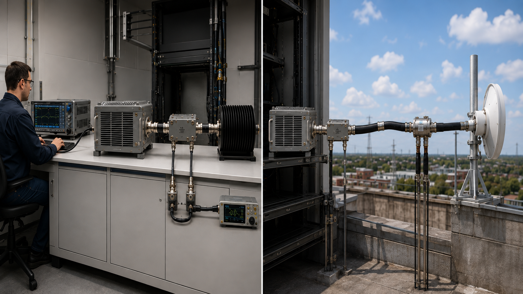
Dummy load testing can make an RF PA look ready for acceptance. The module reaches the expected output, current looks normal, and no protection alarm appears under a controlled load.
The problem begins when the same PA is connected to the installed RF path and the result changes. At that point, comparing the field reading directly with the original bench result can lead engineers to blame the wrong component—or approve a path that was never actually verified.
The useful question is not whether dummy load testing is necessary. It is: what does the dummy-load result actually prove, and what must be checked again before the installed RF path can be accepted?
1. What Does Dummy Load Testing Actually Prove?
A qualified dummy load gives the RF PA a controlled load condition that is useful for establishing a repeatable baseline.
Under a defined test boundary, the team can verify items such as:
- Frequency
- RF input or control target
- PA-port output power
- DC voltage and current
- Duty cycle
- Thermal state
- Forward and reflected power where measured
- Protection status
- Test duration
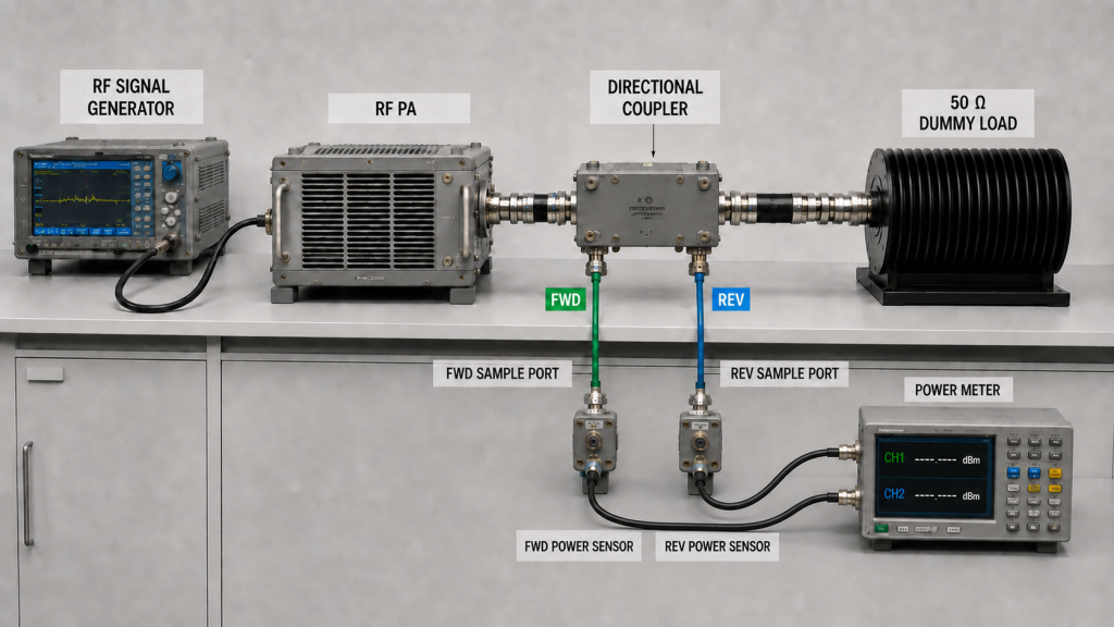
A clean result can show that the PA met the required condition within that controlled test boundary.
It does not prove that the same result will remain unchanged after the installed feeder, connectors, transitions, protection hardware, and antenna are added.
Even the dummy-load baseline itself must be qualified.
A valid baseline depends on a suitable:
- Dummy load
- High-power jumper
- Connector path
- Frequency range
- Power rating
- Measurement reference plane
- Hot-state condition
A component labeled 50 Ω should not automatically be treated as a perfect reference across every frequency, power level, cable condition, and thermal state.
Where the load-side cable is part of the bench setup, its insertion loss, return loss, power handling, connectors, and hot-state behavior should be appropriate for the test. Those details belong in the separate dummy-load cable qualification review.
A statement such as:
“No protection alarm occurred.”
should therefore mean:
No protection event was recorded under the defined frequency, RF operating point, DC supply, load, duty cycle, thermal state, and test duration.
It should not be expanded into a claim that the PA has already been proven stable under every installed RF-path condition.
2. What Changes When the Installed RF Path Replaces the Dummy Load?
The installed path adds electrical and physical conditions that are either absent or intentionally minimized during a controlled dummy-load test.
Three changes matter most.
Insertion Loss
The RF power available at the PA output connector is not automatically the same as the power available farther down the path.
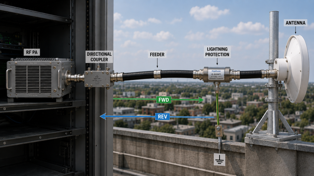
Loss can occur through:
- Feeder cable
- Connectors
- Adapters or transitions
- Filters
- Lightning-protection hardware
- Other passive RF components
This is why PA-port output and downstream power should not be compared as though they were the same reference plane.
Detailed feeder-loss measurement belongs in the RF PA feeder cable loss check rather than being repeated here.
Mismatch and Reflected Power
A controlled dummy load is intended to present a well-defined load condition.
The installed RF path may present a different impedance condition because of the combined feeder, connectors, transitions, antenna, installation quality, and operating environment.
That can change:
- Forward power
- Reflected power
- VSWR or return loss
- PA current
- Protection behavior
- Hot-state RF performance
Higher reflected power does not by itself identify which component caused the mismatch. It shows that the real load condition differs from the controlled baseline and that the path requires further isolation.
Installation and Environment
The installed system also introduces conditions that a bench setup may not reproduce, including:
- Cable routing
- Bend radius
- Connector assembly
- Mechanical stress
- Moisture exposure
- Antenna mounting
- Grounding and bonding
- Temperature variation
- Outdoor hardware
Before installation, complete the RF feeder cable qualification against frequency-specific loss, planned route length, RF power and duty cycle, connector interfaces, routing, environmental limits, and required approval evidence.
An antenna-feed issue should be isolated as an installed-path problem rather than folded into a generic “PA failure.” The dedicated RF PA antenna feed interface check covers that boundary in more detail.
Dummy Load vs Installed RF Path
| Test Boundary | What It Can Show | What It Does Not Prove by Itself |
|---|---|---|
| Qualified dummy-load test | PA behavior under a controlled RF load and defined electrical/thermal condition | Final feeder, connector, antenna, or site performance |
| PA-port power measurement | RF output at the defined PA-side reference plane | Power delivered at a downstream reference plane |
| Installed-path test | Behavior with the actual feeder, transitions, and antenna path | Root cause of a bad result unless the path is isolated |
| Installed hot-state test | Performance after the real RF path and thermal condition are established | Performance outside the tested frequency, duty, load, or environmental boundary |
The two tests therefore answer different questions.
The dummy load establishes a controlled baseline.
The installed path determines whether that baseline still translates into acceptable system behavior after the real RF chain is added.
3. Which Measurement Reference Plane Should the Team Compare?
Many apparent disagreements between bench and field results are actually disagreements between measurement planes.
For example:
- 100 W measured at the PA output connector
- 100 W calculated after a characterized path correction
- 100 W measured at the antenna input
- 100 W net power accepted at the antenna terminals
- 100 W described as radiated power
are not automatically the same quantity.
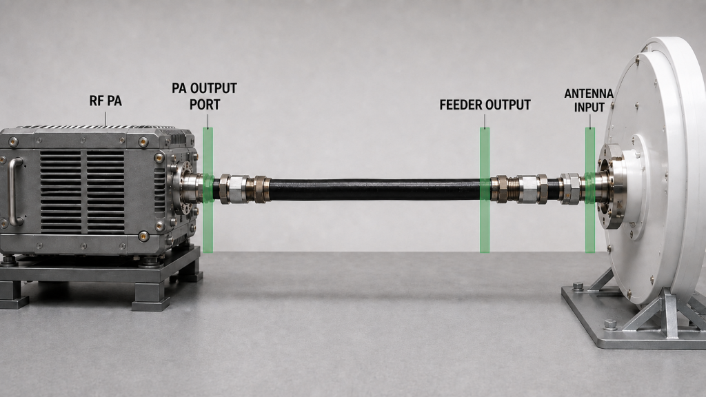
Before comparing results, define exactly where the power applies.
Common reference planes include:
- PA output port
- Coupler or measurement point
- Feeder input
- Feeder output
- Antenna input
If cable, connector, attenuator, coupler, or other path effects are corrected mathematically, the record should distinguish:
- Raw measured value
- Correction or de-embedding method
- Correction basis
- Corrected value
- Reference plane represented by that value
This becomes especially important when mismatch is present.
Forward power at the antenna input is not automatically the same as net power accepted at the antenna terminals, and net accepted power is not the same as radiated power.
Radiated system performance requires additional antenna information such as gain, efficiency, pattern, polarization, and the relevant system-level definition.
Where mismatch and accepted RF power need to be evaluated in detail, use the separate usable RF output under antenna mismatch analysis.
The Mother Page rule is simpler:
Do not compare two power numbers until both their measurement definitions and reference planes are known.
4. How Should Dummy-Load and Installed-Path Results Be Compared?
The strongest comparison changes the RF path while keeping the other important test boundaries as consistent as practical.
When the purpose is to isolate the effect of the installed RF path, keep the following consistent unless one of them is intentionally being evaluated:
- Frequency
- RF input or control target
- DC supply boundary
- Duty cycle
- Relevant thermal state
- Cooling condition
- Measurement definition
- Measurement reference plane
- Protection configuration
Then compare the controlled dummy-load baseline with the installed-path result.
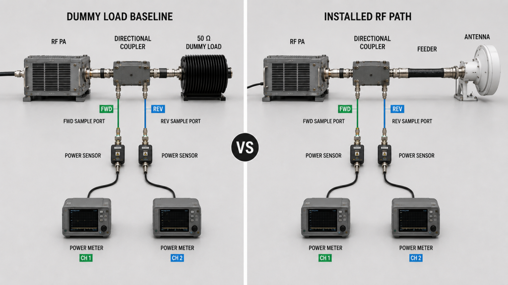
Useful measurements may include:
- PA-port forward power
- Reflected power
- VSWR or return loss
- DC voltage
- DC current
- Hot-state RF output
- Protection or derating status
- Downstream power at an agreed reference plane
- Relevant temperature
- Test duration
A difference between the two tests is meaningful only when the team can tell what changed intentionally and what remained controlled.
For example, a cold dummy-load test and a hot installed-path test do not isolate the effect of the antenna chain alone.
Likewise, changing the frequency, drive level, supply voltage, duty cycle, and RF path at the same time makes root-cause attribution weak.
Compare the Same Engineering Quantity
If the dummy-load report gives PA-port output but the field test gives antenna-input power, either compare both results at their own clearly labeled reference planes, or move them to one agreed plane using a characterized correction method that is valid for the measured path and load condition.
Where mismatch materially affects the result, do not rely on a simple scalar cable-loss correction alone.
Depending on the required accuracy and measurement architecture, the path may need an appropriate calibration, characterized network correction, or de-embedding method before a result is represented at another reference plane.
Do not silently subtract a “typical cable loss” and present the result as though it were directly measured at the corrected plane.
Compare Protection Behavior Too
The installed path may change PA behavior even when the forward-power number initially looks acceptable.
Record whether the real path changes:
- Reflected-power alarm
- VSWR protection
- Current limiting
- Output derating
- Shutdown
- Recovery behavior
A complete comparison therefore includes both RF performance and protection state.
5. What Evidence Proves Installed RF-Path Readiness?
A field screenshot showing one power number is not enough to approve the installed RF path.
Useful evidence should connect four layers.
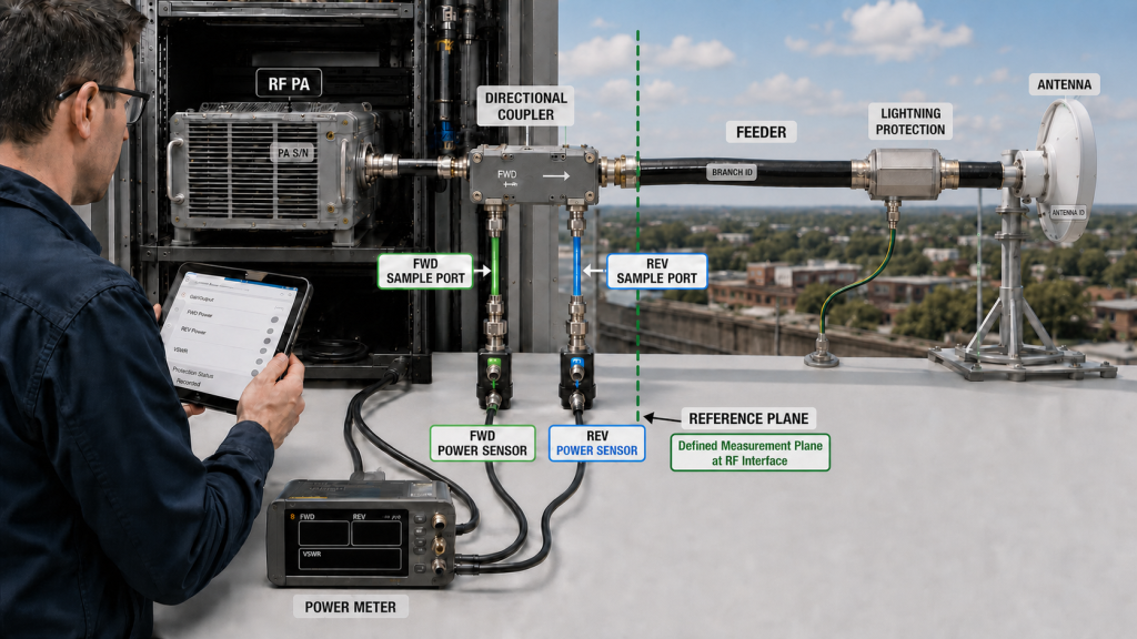
1. PA Baseline
Record the controlled dummy-load condition, including:
- PA S/N
- Frequency
- RF operating point
- DC voltage/current
- Duty cycle
- Thermal state
- PA-port output
- Reflected-power or load condition
- Protection status
2. Installed-Path Configuration
Identify what was added between the PA and antenna, such as:
- Feeder
- Connectors
- Adapters
- Filters
- Lightning-protection devices
- Antenna-feed transition
- Antenna
The actual installed path should be traceable rather than described only as “connected to antenna.”
3. Comparable RF Evidence
Record the field result at a defined reference plane and include, where relevant:
- Forward power
- Reflected power
- VSWR or return loss
- Raw measured power
- Characterized reference-plane correction where used
- Corrected value and represented reference plane
- DC voltage/current
- Hot-state result
- Protection behavior
If mismatch materially affects the measurement, record the method used to account for that condition rather than treating nominal insertion loss as sufficient correction.
4. Traceability
Tie the evidence to:
- PA S/N
- Cabinet or channel position
- Test date
- Installed RF path
- Antenna or branch identification
- Measurement equipment or setup where required
- Test boundary
For fixed-site or perimeter deployments, long feeder runs, outdoor connectors, lightning protection, mast routing, and environmental exposure can make installed-path evidence particularly important. But the same acceptance principle applies to any system where the final RF path differs materially from the controlled bench setup.
When dummy-load and installed-path evidence are both part of module approval, define the frequency range, target PA-port output, installed RF-path boundary, load condition, hot-state requirement, protection behavior, and required test report before selecting custom RF power amplifier modules.
6. What Should You Check When the Dummy Load Passes but the Installed Path Fails?
A clean dummy-load result changes the troubleshooting direction, but it does not automatically prove that the PA is fault-free under the real load.
The next investigation should separate:
- Module behavior
- Installed RF path
- Measurement reference
- Environmental or installation condition
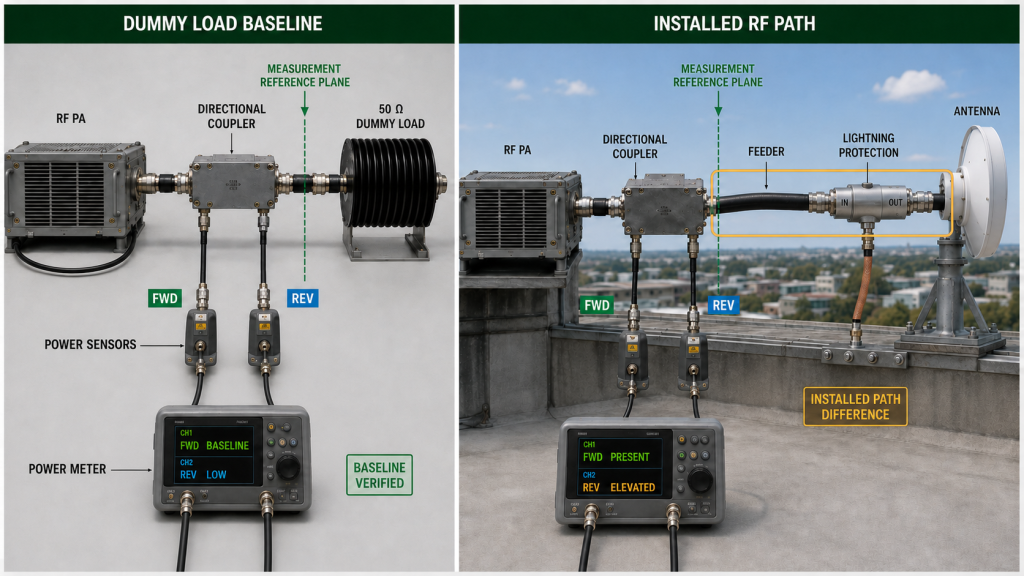
A practical sequence is:
- Preserve the original failing condition before changing several variables.
- Confirm the dummy-load baseline under the defined test boundary.
- Confirm the measurement reference plane used in both tests.
- Measure forward and reflected power on the installed path.
- Check whether the difference is consistent with the characterized path and measurement method.
- Inspect the relevant feeder, connector, transition, protection device, and antenna path.
- Compare the result at a controlled thermal state.
- Record protection or derating behavior.
- If practical, isolate sections of the installed path.
- Repeat the comparison after one intentional change at a time.
If the controlled comparison points specifically to an adapter or removable transition, use the RF adapter error check to separate insertion loss, mismatch, and connection repeatability before assigning the difference to the PA.
If the difference follows a terminated cable assembly or one connector end instead, use the RF connector crimping diagnosis to isolate the termination before assigning the fault to the PA.
Pass-on-Dummy / Fail-on-Path Diagnostic Table
| Observed Pattern | What It Suggests | Next Check |
|---|---|---|
| PA meets the controlled dummy-load baseline but installed-path forward power is lower | Installed-path loss, reference-plane difference, or load-dependent PA behavior becomes more relevant | Confirm reference planes, characterize the path, and compare PA behavior under the installed load |
| Reflected power rises only after the installed path is connected | Installed mismatch becomes more likely | Isolate feeder, transitions, antenna feed, and antenna boundary |
| Different PAs show the same problem on one installed branch | Branch-specific behavior becomes more likely | Check branch hardware and reference-plane measurements |
| The same PA shows abnormal behavior on both qualified dummy load and installed path | Module-specific behavior becomes more credible | Continue PA-level diagnosis under controlled conditions |
| Power looks acceptable but VSWR protection activates | Load condition may be outside the approved boundary | Review FWD/REV, reflection requirement, and protection behavior |
| Cold test passes but hot installed-path test changes | Thermal state is part of the difference | Repeat using matched thermal boundaries before assigning root cause |
These patterns indicate where the next investigation should go.
They do not by themselves prove which connector, cable, antenna, or PA component is defective.
A clean dummy-load result shifts the next investigation toward the installed path when the problem appears only after that path is added under otherwise comparable operating and measurement conditions, but it does not prove that the PA is fault-free under every real-load condition.
7. What Should the RFQ Define for Dummy-Load and Installed-Path Approval?
An RFQ should not use vague acceptance language such as:
- “100 W output”
- “VSWR OK”
- “Dummy load passed”
- “Antenna test passed”
- “Cable loss acceptable”
Each statement needs a measurement boundary.
RFQ Acceptance Checklist
| RFQ Item | What to Define | Why It Matters | Expected Evidence |
|---|---|---|---|
| Dummy-load baseline | Frequency, target RF output, load condition, duty cycle, DC supply, thermal state | Establishes the controlled PA reference | S/N-linked dummy-load record |
| Dummy-load path | Load, jumper, connectors, frequency/power capability | Prevents an unqualified bench path from becoming the reference | Load-path qualification or defined setup |
| PA output reference plane | Exact point where PA output is specified | Prevents downstream loss from being confused with PA output | Labeled power measurement |
| Installed RF path | Feeder, connectors, transitions, filters, protection devices, antenna | Defines what the final acceptance actually includes | Installed-path record |
| Reference-plane correction | Raw reading, characterized path correction or de-embedding method, applicable load condition, and corrected reference plane | Prevents an unsupported scalar loss assumption from being treated as actual power at another plane | Raw data, correction basis, and corrected result |
| Reflection requirement | Required VSWR or return loss, measurement method, frequency, and reference plane | Defines the permitted installed-path mismatch | Calibrated reflection measurement |
| High-power mismatch evidence | Required FWD/REV power or protection behavior at the stated directional measurement plane | Shows how the PA behaves under the powered installed-load condition | FWD/REV record and protection log |
| Thermal condition | Cold, transition, or stabilized hot-state requirement | Prevents cold-only evidence from being generalized | Time/temperature-linked test record |
| Protection behavior | Allowed alarm, foldback, derating, shutdown, and recovery state | Defines whether the PA remains acceptable under the real load | Protection log |
| Installed-path pass criterion | Required performance at the agreed final reference plane | Separates PA acceptance from path acceptance | Field or system acceptance record |
| Traceability | PA S/N, branch, antenna/path ID, configuration | Allows later production and service comparison | S/N-linked acceptance report |
Keep the Two Acceptance Stages Separate
A strong RFQ distinguishes:
Stage 1 — Controlled PA baseline
The supplier demonstrates the required PA behavior using a defined and qualified dummy-load setup.
Stage 2 — Installed RF-path acceptance
The buyer or integration team verifies the final feeder, connectors, antenna path, measurement reference, reflection boundary, thermal state, and protection behavior.
Passing Stage 1 does not automatically complete Stage 2.
After Stage 2 is passed, use the RF PA VSWR field-failure prevention framework to decide which installed RF-path changes reopen the accepted mismatch boundary before field release.
Likewise, a poor Stage 2 result should not automatically be assigned to the PA before the installed path, measurement boundary, and load-dependent PA behavior are checked.
FAQ
Is dummy load testing still necessary?
Yes.
A qualified dummy-load test provides a controlled baseline for PA output, DC behavior, protection status, and thermal performance under a defined RF load.
The mistake is not using a dummy load. The mistake is treating that controlled result as proof of the final installed RF path.
Can an RF PA pass a dummy load test and still fail on the installed RF path?
Yes.
The installed path can add insertion loss, mismatch, connector or transition problems, different thermal conditions, and a different measurement reference plane. The PA itself may also respond differently to the real load condition.
A dummy-load pass therefore establishes a baseline, not final system approval.
What should be compared before installed-path approval?
Compare the dummy-load and installed-path results using clearly defined measurement planes and controlled test boundaries.
At minimum, confirm the relevant frequency, RF operating point, DC condition, duty cycle, thermal state, forward/reflected behavior, reference-plane correction where used, protection status, and S/N-linked configuration.
Conclusion
Dummy load testing is necessary because it establishes a controlled RF PA baseline, but it cannot approve the installed RF path by itself.
Once the feeder, connectors, transitions, protection hardware, and antenna are added, the RF PA may see a different load and the measured power may refer to a different reference plane. A result that passed on the bench can therefore change without proving that either the PA or the installed path alone is the root cause.
The correct acceptance method is to keep the dummy-load baseline and installed-path test as two defined stages, compare them under controlled operating conditions, identify the measurement reference plane, use a correction method appropriate to the path and load condition, record the required reflection or FWD/REV evidence, include hot-state and protection behavior where required, and maintain S/N-linked traceability.
If the dummy-load baseline passes but the installed-path result fails under otherwise comparable operating and measurement conditions, isolate the installed path and reference-plane difference before replacing the PA—but do not use the dummy-load result alone to declare the module fault-free under the real load.
For an RFQ review, contact RF SKYPOWER with your operating frequencies, target PA-port output, installed RF-path layout, feeder and connector path, antenna model, required measurement reference plane, dummy-load condition, VSWR or return-loss boundary, required FWD/REV evidence, duty cycle, hot-state requirement, protection criteria, and required S/N-linked acceptance evidence.