


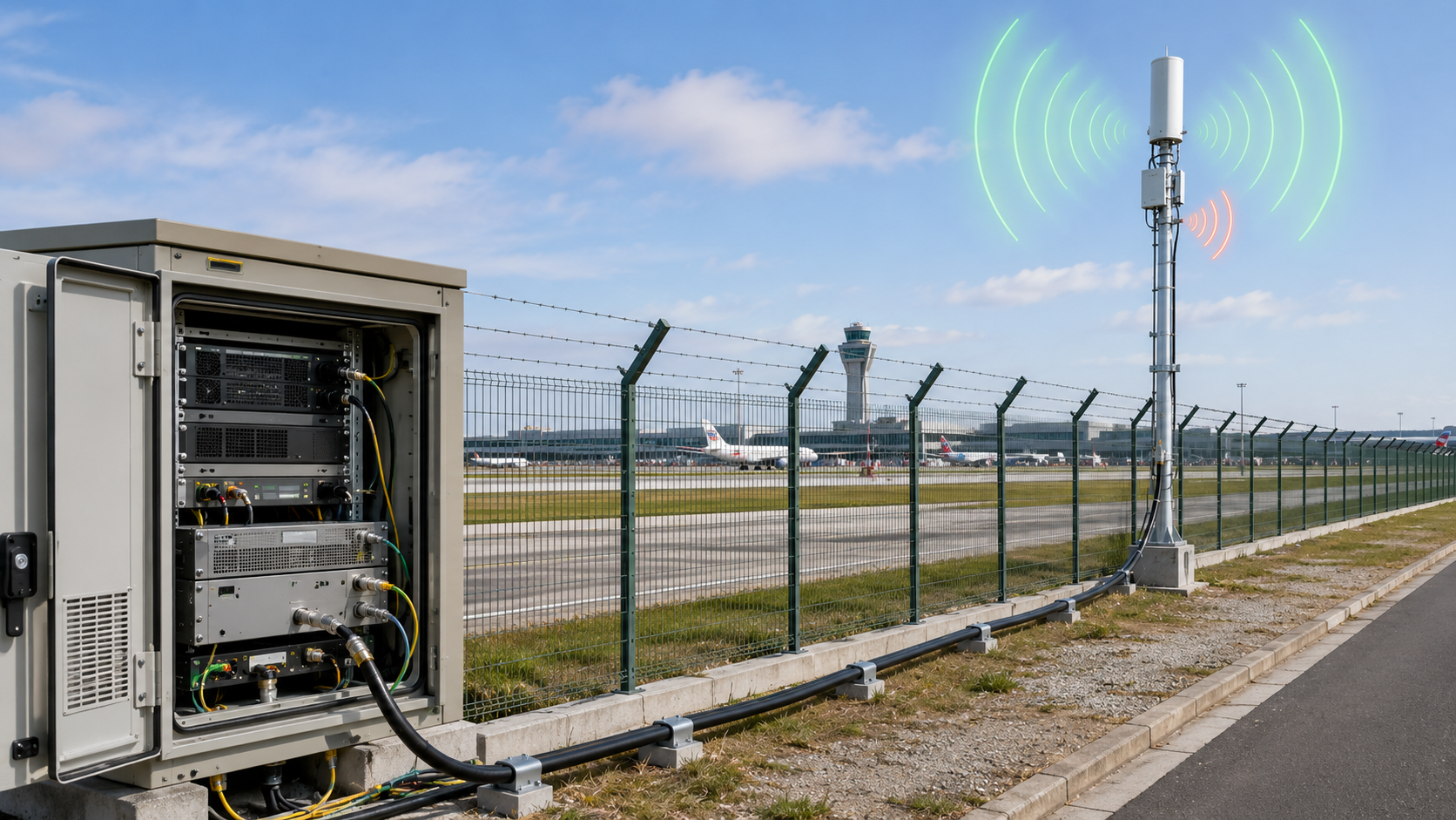
Usable RF Output Power changes under antenna mismatch because an RF Power Amplifier is no longer working into the ideal 50Ω load used during dummy-load testing. A module may produce stable output on a factory dummy load, but the installed airport perimeter antenna path can add feeder loss, connector transitions, waterproof joints, lightning protection, reflected power, VSWR change, thermal stress, and protection behavior that alter the power actually delivered to the antenna.
The central conflict is simple: dummy-load output proves the PA module can generate power under a controlled load, but installed antenna output proves how much of that power remains usable in the real C-UAS RF chain. For system integrators, RF engineers, and procurement reviewers, the practical question is not only “Can the module make 100W?” The better question is “How much usable output remains after the real antenna load, feeder path, and protection status are included?”
When selecting RF Power Amplifier modules for C-UAS integration, engineers should verify output under both dummy-load and installed antenna conditions before treating PA-port power as system-ready power.
1. What Dummy Loads Miss About Usable RF Output Power
Dummy load output does not prove antenna-port power because Usable RF Output Power depends on the real load seen by the RF Power Amplifier after antennas, feeder paths, connectors, waterproof joints, and installation structures are added. A clean dummy-load result is a necessary baseline, but it is not the same as installed antenna performance.
Here’s the engineering point: a dummy load is usually much more controlled than an airport perimeter antenna path. The airport installation includes physical distance, outdoor interfaces, lightning protection, mounting structures, and frequency-dependent antenna behavior.
What Does Dummy Load Testing Actually Prove?
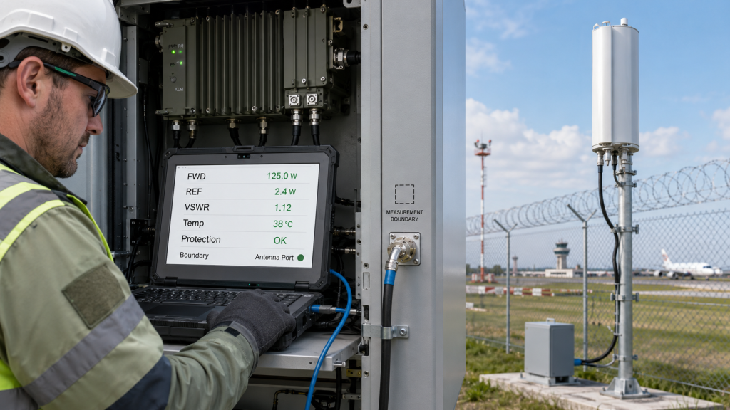
Dummy-load testing proves that the PA module can deliver power into a controlled RF load. It helps verify baseline output, current, thermal behavior, and protection response before the module is connected to a more variable field antenna.
A useful dummy-load test can confirm:
- PA module output capability
- Supply current under a known load
- Basic thermal behavior
- Protection stability under a controlled condition
- Factory repeatability before shipment
Before comparing dummy-load and antenna-load results, engineers should define RF power measurement points so PA-port output, cabinet output, feeder-end power, and antenna-port power are not mixed.
Why Does the Real Antenna Path Change the Result?
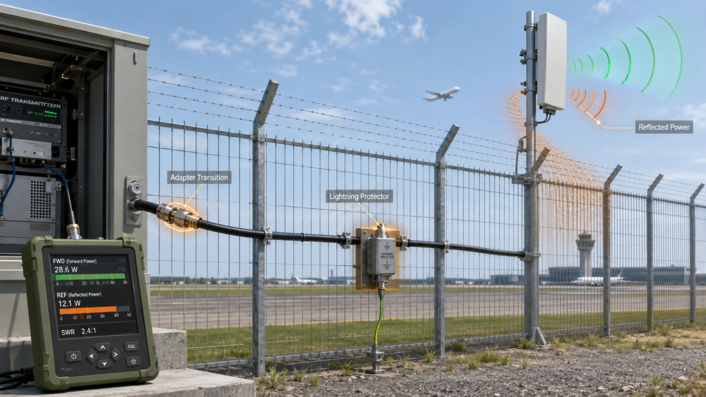
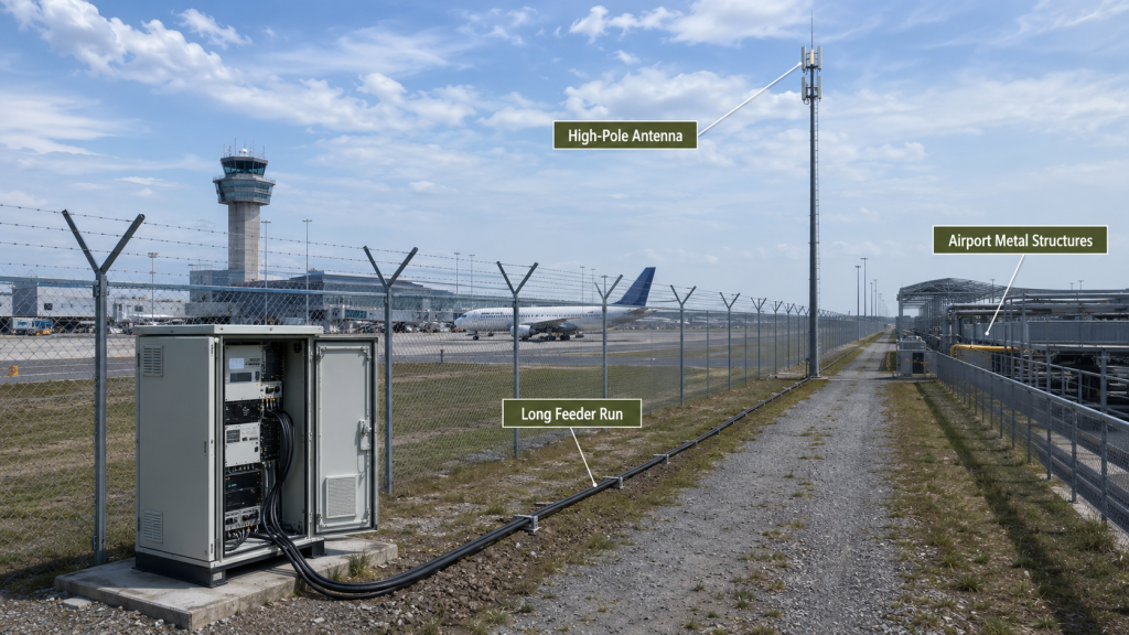
The installed antenna path may include a long feeder cable, lightning protector, waterproof connector, adapter, mounting pole, ground structure, and nearby metal surfaces. Each part can change delivered power or reflected power.
Key Takeaway: Dummy-load output proves controlled module output, but antenna-port output proves installed system usability.
| Wrong Assumption | Better Check | Why It Matters |
|---|---|---|
| Dummy-load 100W means antenna 100W | Measure installed antenna path | Finds real delivered power |
| 50Ω label proves field match | Check VSWR after installation | Finds load mismatch |
| PA-port power equals antenna power | Define measurement boundary | Prevents false approval |
| Factory test proves field output | Compare field antenna condition | Supports acceptance |
This table helps engineers separate module capability from installed antenna-chain behavior.
2. When Is Antenna Mismatch Acceptable?
Antenna mismatch is acceptable only when Usable RF Output Power, reflected power, VSWR, module temperature, voltage status, and protection behavior all remain within project-defined limits. A mismatch is not automatically a failure, but it must be controlled, measured, and explainable.
The practical risk is clear: “no major alarm” does not always mean “no output change.” A system can avoid shutdown while still losing usable antenna-port power.
What Makes Mismatch Manageable?
A mismatch may be manageable when reflected power is low enough, protection does not reduce output, and the antenna-port target is still met. The key is to judge mismatch as a system condition, not only a VSWR number.
Mismatch may be acceptable when:
- VSWR stays within the approved module and system range
- Reflected power is stable
- Temperature does not rise abnormally
- Voltage and current stay within expected behavior
- Protection does not back off or shut down output
- Antenna-port power still meets the project target
- The condition is repeatable during acceptance
If reflected power rises after connecting the field antenna, engineers should review RF Power Amplifier VSWR protection before judging the module output alone.
Why Is Protection Status Not the Only Answer?
Protection status is important, but it is not the only acceptance signal. A module may not trigger full protection, yet reflected power can still reduce net delivered power or increase heat stress.
Key Takeaway: Acceptable mismatch is defined by usable output and stable operating state, not by the absence of a dramatic failure.
| Condition | Usually Acceptable? | Better Check |
|---|---|---|
| Low reflected power | Yes | Confirm antenna-port power |
| Stable mild VSWR | Often | Check temperature and current |
| No alarm but lower output | Not enough | Review delivered power |
| Frequent VSWR warning | Risky | Inspect antenna path |
| Protection back-off | Not normal output | Recheck load and installation |
This table helps teams avoid treating mismatch as either harmless or catastrophic without evidence.
3. When Does Antenna Mismatch Become an Output Power Risk?
Antenna mismatch becomes an output power risk when Usable RF Output Power is reduced by reflected power, feeder-chain mismatch, frequency-sensitive antenna behavior, or protection back-off under real C-UAS operating conditions. The risk is not only module damage; it is losing usable power at the installed antenna.
This is where system integrators should pay attention: the PA module may still be healthy while the installed antenna path makes the usable output lower than expected.
Which Conditions Should Trigger Extra Review?
Airport perimeter systems create several conditions where antenna mismatch can become more visible. A single mismatch source may be manageable, but multiple installation variables can combine.
Review mismatch risk when you see:
- Long feeder routes from cabinet to antenna
- Waterproof joints and outdoor connectors
- Lightning protection in the RF path
- Multiple adapters or transitions
- High-pole or fence-mounted antennas
- Nearby metal structures
- Wideband or multi-band antennas
- 2.4GHz or 5.8GHz high-frequency paths
- Continuous or high-duty operation
- Field acceptance based on installed antenna output
Antenna mismatch should be reviewed together with RF Power Amplifier feeder and connector loss because the same installed RF path affects both delivered power and reflected power.
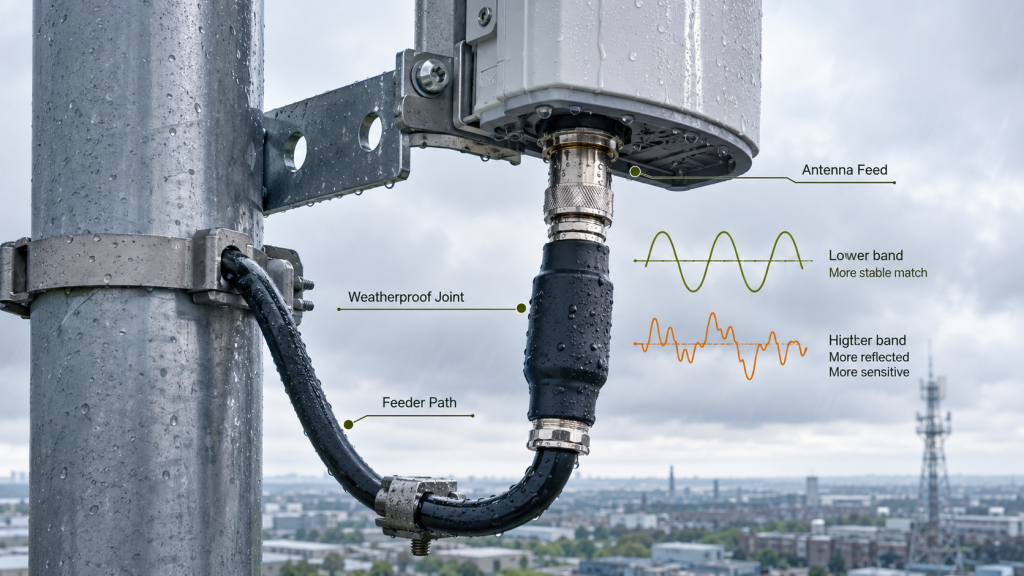
Why Is High Frequency More Sensitive?
High-frequency paths are less forgiving of connector quality, cable routing, adapter transitions, and antenna feed details. A path that looks acceptable at lower frequencies may show more output variation at higher bands.
High-frequency paths need extra review because 5.8GHz RF Output can become more sensitive when antenna mismatch and feeder transitions are added.
Key Takeaway: Mismatch becomes an output risk when the installed RF path changes delivered antenna power, not only when it triggers a major alarm.
| Trigger Condition | Output Risk | Better Review |
|---|---|---|
| Long feeder path | Lower antenna-port power | Check loss and VSWR |
| Lightning protector | Extra transition point | Verify frequency rating |
| Metal mounting area | Antenna detuning | Recheck installed VSWR |
| High-frequency band | Higher sensitivity | Test key frequency points |
| High-duty operation | Heat and protection stress | Monitor over time |
This table helps project teams identify when antenna mismatch must be part of output approval.
4. What Antenna Mismatch Does to Usable RF Output Power
Antenna mismatch changes real C-UAS effectiveness because Usable RF Output Power depends on the power actually delivered to the installed antenna, not only the forward power generated at the PA output. If reflected power rises or protection behavior changes, the antenna-port power available to the perimeter system can fall.
Here’s the field reality: mismatch may not appear as a complete failure. It may appear as weaker channel balance, inconsistent antenna directions, higher temperature, or field results that do not match the factory report.
Where Does the System-Level Effect Appear?
Antenna mismatch can reduce useful output in several ways. Some effects appear immediately during testing, while others appear during long-duty operation or field retesting.
Mismatch can affect:
- Antenna-port usable output
- Multi-directional antenna consistency
- Multi-band output balance
- Thermal margin
- VSWR alarm behavior
- Customer acceptance confidence
- Maintenance troubleshooting
For multi-antenna airport systems, antenna mismatch can affect RF Power Amplifier output consistency between channels, bands, and directions.
Why Does Forward Power Alone Mislead?
Forward power alone does not show whether the antenna accepts the power efficiently. If reflected power increases, the net delivered power and thermal condition may change even when the forward reading looks acceptable.
Key Takeaway: Antenna mismatch affects the installed system by changing usable output, channel balance, and protection margin.
| Mismatch Effect | System Consequence | Better Check |
|---|---|---|
| Higher reflected power | Less delivered output | Record forward/reflected power |
| Band-specific mismatch | Weak frequency zone | Test critical bands |
| Directional antenna mismatch | Uneven perimeter behavior | Compare antenna points |
| Protection back-off | Lower output state | Review alarm logic |
| Higher heat | Reduced long-duty margin | Monitor temperature |
This table helps engineers connect VSWR data to system-level RF output judgment.
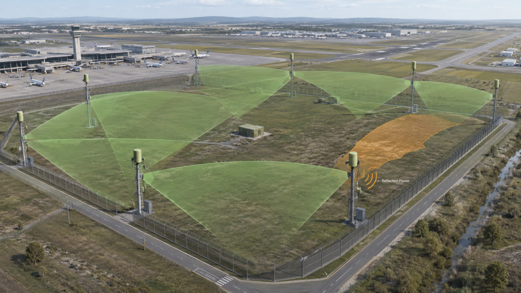
5. How to Check Usable RF Output Power at Airport Sites
Airport perimeter deployments reveal antenna mismatch because Usable RF Output Power can change after long feeder paths, high-pole antennas, waterproof joints, lightning protection, metal structures, and multi-directional coverage are installed. An airport may look open, but its RF chain is not automatically simple.
This is where the airport scenario matters: perimeter antennas are often placed where coverage needs them, not where the RF cabinet is easiest to install. That distance and installation reality can change both delivered power and reflected power.
Which Airport Conditions Change Antenna Match?
Airport perimeter sites often include practical RF constraints that do not exist in a bench test.
Common conditions include:
- Remote antenna points along the perimeter
- Long feeder runs from cabinet to pole
- Lightning protection and grounding structures
- Waterproof outdoor connectors
- High-pole or fence-mounted antennas
- Nearby metal fencing, buildings, or service structures
- Multiple antenna directions
- Limited maintenance windows
In airport perimeter C-UAS deployment, long feeder paths, high-pole antennas, waterproof joints, and lightning protection can change antenna match after installation.
Why Is the Airport Case Useful?
A real airport low-altitude security case shows why antenna stability, controlled RF behavior, and repeatable validation matter before final deployment. Airport projects need predictable RF output evidence because field changes can be costly after installation.
Key Takeaway: Airport perimeter deployment turns antenna mismatch from a lab concern into an installed RF-chain acceptance issue.
| Airport Condition | Mismatch Risk | Better Check |
|---|---|---|
| Remote perimeter antenna | Long RF path | Confirm feeder and VSWR |
| High-pole installation | Detuning from structure | Test after mounting |
| Lightning protection | Added transition | Verify frequency behavior |
| Waterproof joint | Contact and sealing risk | Inspect and retest |
| Multiple directions | Uneven load behavior | Compare antenna points |
This table helps buyers see why airport perimeter output must be checked under installed antenna conditions.
6. Why Do Feeder, Connectors, Weather, and Frequency Change Match?
Feeder, connectors, weather, and frequency change antenna match because Usable RF Output Power depends on the full load path seen by the RF Power Amplifier, not only the antenna model name. The antenna may be rated correctly, while the installed path still creates mismatch, reflected power, or unstable output.
The better check is simple: review the whole RF path from PA output to antenna feed, not only the antenna datasheet.
Which Installed Parts Affect the Load?
Several field components can change the load seen by the PA. The effect may be small alone but important when repeated across a perimeter system.
Review these items:
- Feeder length and cable grade
- Cable bend radius and routing
- Connector type and assembly quality
- Adapter count
- Waterproof joints
- Lightning protection
- Grounding and mounting structure
- Antenna feed interface
- Weather exposure
- Frequency band and edge-frequency behavior
If mismatch appears only after installation, engineers should also review RF Power Amplifier antenna feed problems such as contact pressure, plating, contamination, and outdoor connection quality.
Why Does Weather Matter?
Rain, humidity, wind, temperature swing, and seal condition can change connector behavior and nearby antenna environment. For long-term airport perimeter systems, a one-time dry-weather check may not prove stable mismatch behavior.
Key Takeaway: Antenna match is created by the installed RF chain, not by the antenna label alone.
| Installed Factor | Possible Effect | Better Check |
|---|---|---|
| Long feeder | Loss and load uncertainty | Measure path behavior |
| Connector quality | Reflection point | Inspect and torque correctly |
| Waterproof joint | Contact or sealing shift | Test after installation |
| Lightning protection | Frequency-sensitive transition | Verify rated band |
| Weather exposure | Drift over time | Plan repeatable checks |
This table helps teams identify mismatch sources beyond the antenna itself.
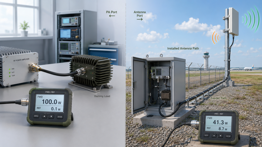
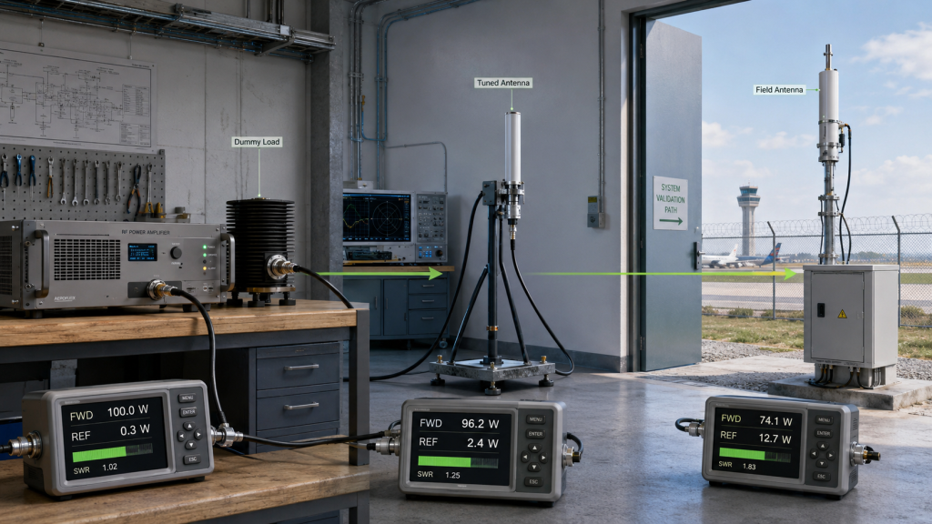
7. How Do Dummy Load, Tuned Antenna, and Field Antenna Tests Differ?
Dummy load, tuned antenna, and field antenna tests differ because Usable RF Output Power is judged under different load conditions in each test. A dummy load answers whether the PA can produce output under a controlled load, while an installed field antenna answers whether the final RF chain can deliver usable power.
The selection risk appears here: treating all three tests as equivalent can cause false confidence during acceptance.
What Does Each Test Answer?
Each load condition answers a different engineering question. The tests should be seen as progressive evidence, not substitutes for each other.
Use this distinction:
- Dummy load: proves PA baseline output under a controlled 50Ω load
- Tuned lab antenna: checks antenna behavior under a more controlled environment
- Installed field antenna: proves the real RF chain after feeder, mounting, weatherproofing, and environment
- Field retest: checks repeatability after installation or maintenance
Mismatch should also be checked under RF Power Amplifier continuous output conditions because reflected power and heat behavior can change during long-duration operation.
Why Can a Field Antenna Change the PA Reading?
The PA may respond differently when reflected power changes. Depending on protection logic, load condition, and thermal state, the output reading may reduce, fluctuate, or trigger alarms.
Key Takeaway: The right test depends on the question being answered: module capability, antenna match, or installed system usability.
| Test Condition | What It Proves | What It Cannot Prove |
|---|---|---|
| Dummy load | PA baseline output | Installed antenna behavior |
| Tuned lab antenna | Controlled antenna match | Airport site interaction |
| Field antenna | Installed RF chain behavior | Pure module capability alone |
| Field retest | Repeatability after installation | Factory condition by itself |
This table helps buyers choose the right evidence instead of overusing one test result.
8. How to Prove Usable RF Output Power With VSWR Evidence
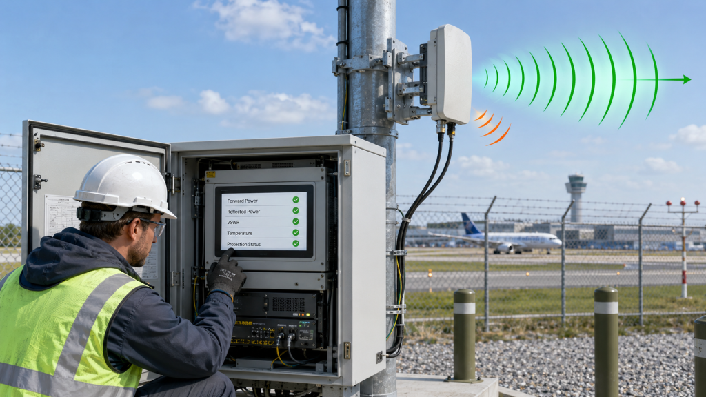
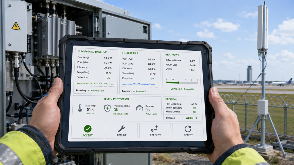
VSWR evidence should verify Usable RF Output Power by recording forward power, reflected power, VSWR, antenna-port power, temperature, voltage, protection status, load condition, and measurement boundary. A simple “VSWR normal” statement is not enough for airport perimeter acceptance.
Here’s the practical risk: without protection and load data, a lower output reading becomes a guessing game. The issue may be the antenna, feeder, connector, heat, supply voltage, or module response.
What Should the Report Include?
A useful report should connect the output number to the load condition that produced it.
Request these fields:
- Module S/N
- Frequency points tested
- Forward power
- Reflected power
- VSWR or SWR
- PA-port, feeder-end, or antenna-port boundary
- Load type: dummy load, tuned antenna, or field antenna
- Feeder length and connector path
- Module-end voltage and current
- Temperature state
- VSWR, temperature, and voltage protection status
- Test duration and duty condition
If output changes under field antenna load, engineers should also review RF Power Amplifier protection logic so alarm feedback, output action, and recovery behavior are understood before final judgment.
Why Does Protection Feedback Explain Output Change?
VSWR, temperature, and voltage protection are useful not only for preventing damage. They also help engineers identify whether output decline comes from load mismatch, thermal stress, supply behavior, or the PA module itself.
Key Takeaway: Usable output under mismatch should be proven with forward/reflected power, protection status, and a defined measurement boundary.
| Weak Evidence | Better Evidence | Why It Matters |
|---|---|---|
| VSWR looks okay | VSWR plus reflected power | Shows load severity |
| Forward power only | Forward and reflected power | Shows delivered behavior |
| No boundary | Defined reference point | Prevents data mismatch |
| No protection status | Alarm and back-off record | Explains output change |
| No load description | Field antenna path record | Supports retesting |
This table helps procurement and engineering teams request evidence that explains power behavior under mismatch.
9. What RFQ Data Defines Usable RF Output Power
Before quotation, buyers should share antenna VSWR, feeder length, connector path, lightning protection, mounting environment, measurement boundary, and whether Usable RF Output Power must meet targets under the installed antenna load. A request for “100W PA module” alone is not enough for airport perimeter output approval.
This is where RFQ quality decides later acceptance clarity. If the antenna path is unknown, the supplier can only validate output under a standard dummy load.

What Antenna and RF Path Data Matter Most?
The buyer does not need perfect final drawings at the first discussion, but the RFQ should provide enough information to avoid a wrong output assumption.
Share or request:
- Target frequency bands
- Required output boundary
- Antenna model and VSWR data
- Antenna mounting position
- Antenna height and nearby metal structures
- Feeder length and cable type
- Connector and adapter count
- Waterproof joint details
- Lightning protection model
- Field antenna acceptance requirement
- VSWR and reflected-power report requirement
- Temperature, voltage, and protection feedback requirement
Antenna mismatch should be reviewed with Low-Altitude Security & C-UAS EW Solutions in mind because airport perimeter RF systems depend on installed antenna-port power, not only PA-port output.
Why Is Installation Context So Important?
Antenna model data is useful, but installation changes the load condition. A high-pole antenna near metal structures, with long feeder and weatherproof joints, may behave differently from the same antenna in a controlled test.
Key Takeaway: A strong RFQ gives the supplier the antenna path context needed to judge usable output, not only module wattage.
| RFQ Item | Why It Matters | Risk If Missing |
|---|---|---|
| Antenna VSWR | Defines load behavior | False output assumption |
| Feeder length | Affects delivered power | Low antenna-port margin |
| Connector path | Adds reflection points | Hidden mismatch |
| Measurement boundary | Defines power meaning | Acceptance dispute |
| Protection feedback | Explains output changes | Poor troubleshooting |
This table helps buyers turn antenna mismatch into a measurable quotation and acceptance condition.
10. How to Judge Usable RF Output Power Under Mismatch
RF output under antenna mismatch is acceptable only when Usable RF Output Power, reflected power, VSWR, protection status, temperature, voltage, and antenna-port output remain within project-defined limits. The final decision should be based on installed RF-chain evidence, not only dummy-load output.
This is the final decision path: approve the module and antenna chain together only when the evidence supports the airport perimeter requirement.
What Decision Sequence Should Engineers Use?
Use a structured review before final approval:
- Confirm dummy-load baseline output.
- Define PA-port, cabinet-output, feeder-end, or antenna-port boundary.
- Confirm the installed feeder and connector path.
- Measure forward power and reflected power.
- Record VSWR or SWR by frequency.
- Check temperature, voltage, and current.
- Review VSWR, temperature, and voltage protection status.
- Compare critical low, center, and high frequency points.
- Confirm antenna-port usable output.
- Decide whether to accept, retune, reroute, replace, or retest.
As an RF Power Amplifier module and C-UAS core component source factory, RF SKYPOWER can support airport perimeter projects by reviewing antenna VSWR, feeder-chain loss, reflected power, measurement boundary, protection status, antenna-port power, and repeatable test evidence before final approval.
When Should the Design Be Adjusted?
The design should be adjusted when reflected power is high, usable antenna-port output is too low, protection frequently intervenes, temperature rises abnormally, or the installed antenna path cannot support repeatable acceptance.
If your airport perimeter C-UAS project has not confirmed antenna VSWR, reflected power, feeder-chain loss, protection status, and antenna-port output, you can review your RF Power Amplifier antenna mismatch conditions with a source-factory engineering team before final approval.
Key Takeaway: Output under mismatch is acceptable only when the installed antenna path still delivers the required usable power without unstable protection or thermal behavior.
| If the Result Shows… | Start With… | Recommended Action |
|---|---|---|
| Good dummy-load output, low antenna output | Antenna path | Check mismatch and feeder loss |
| High reflected power | VSWR and connectors | Inspect load path |
| Output back-off | Protection status | Review alarm logic |
| Hot operation | Thermal and reflected power | Check mismatch heat stress |
| One band weakens | Frequency-specific data | Review high-band match |
This table gives engineering and procurement teams a final acceptance path for antenna mismatch conditions.
FAQ
Can dummy-load power prove field antenna output?
No. Dummy-load power proves baseline PA output under a controlled load, but it does not prove antenna-port power after feeder loss, connectors, lightning protection, and installed antenna mismatch are added.
What should I check when output drops after connecting the antenna?
Start with measurement boundary, forward power, reflected power, VSWR, feeder path, connector condition, module-end voltage, temperature, and protection status. Do not blame the PA module before checking the installed RF path.
Does no VSWR alarm mean antenna mismatch is not a problem?
No. A system may avoid a major alarm while still losing usable output or adding thermal stress. VSWR alarm status should be reviewed together with reflected power and antenna-port power.
Should airport C-UAS acceptance use dummy load or field antenna?
Use both when risk justifies it. Dummy load confirms PA baseline output, while field antenna testing confirms the installed RF chain and antenna-port usable output.
How do I know if mismatch is acceptable?
Mismatch is acceptable when reflected power, VSWR, protection status, temperature, voltage, and antenna-port usable output remain within project-defined limits under the installed antenna condition.
Conclusion
Antenna mismatch changes usable RF output power because the RF Power Amplifier is no longer working into the ideal load used during dummy-load testing. In airport perimeter C-UAS systems, the installed antenna path may include long feeder cables, waterproof connectors, lightning protection, metal mounting structures, multi-directional antennas, and outdoor weather exposure. These conditions can increase reflected power, change VSWR, trigger protection behavior, add heat stress, and reduce the antenna-port power available to the system.
For system integrators, RF engineers, and procurement reviewers, the practical lesson is clear: do not approve RF output power only from dummy-load data. Confirm measurement boundary, antenna VSWR, reflected power, forward power, feeder-chain condition, module-end voltage, temperature behavior, protection status, and repeatable test evidence under the load condition that matches the project.
RF SKYPOWER supports airport perimeter output evaluation by reviewing antenna mismatch risk, feeder and connector path, VSWR feedback, reflected power, thermal margin, voltage status, and antenna-port usable output before final project approval. If your team needs to align PA output, antenna mismatch, feeder-chain assumptions, protection feedback, and airport perimeter acceptance evidence before deployment, you can discuss your project with RF SKYPOWER before field changes become expensive.
Airport perimeter C-UAS performance should be approved by installed antenna-port evidence, not only by a clean dummy-load watt number.