


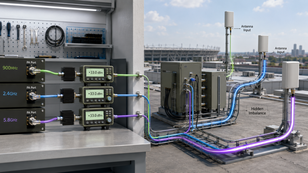
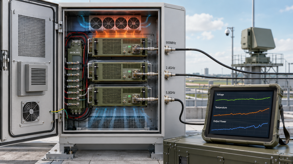
RF Power Consistency should be checked in multi-band C-UAS systems by comparing each active channel under the same measurement boundary, operating condition, antenna path, thermal state, and supply load.A channel that reaches its rated RF Power Amplifier output in a factory test can still behave differently after feeder length, connector count, antenna location, cabinet heat, shared 28V supply, and simultaneous multi-channel operation are included.
The central conflict is simple: rated channel power proves module-side capability, but RF Power Consistency proves system-side balance. For large venues, the practical question is not only whether each 900MHz, 2.4GHz, or 5.8GHz channel can reach its individual wattage target. The harder question is whether all required channels remain predictable, comparable, and repeatable after real venue RF paths are installed.
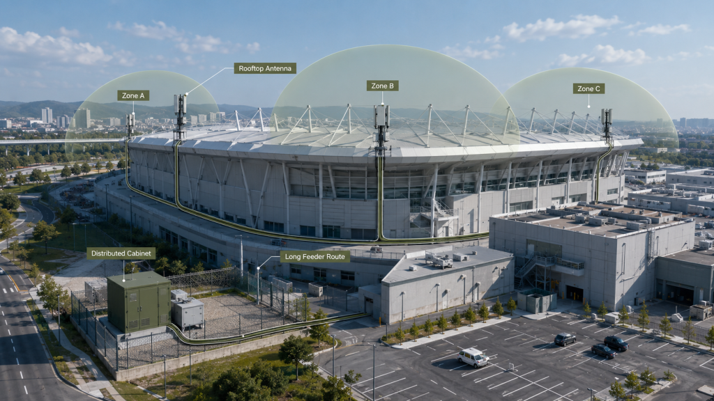
This matters because stadiums, event venues, transport hubs, and high-density urban perimeters often use multiple antenna zones, distributed cabinets, rooftop antenna positions, long feeder routes, and long event-duty operation. If one channel drops, the cause may be the PA module, feeder path, antenna mismatch, thermal coupling, supply voltage, calibration boundary, or protection behavior. A serious consistency review helps engineers separate these causes before acceptance becomes a dispute.
1. What Rated Power Misses About RF Power Consistency
RF Power Consistency cannot be proven by rated power on each channel because single-channel output is measured under controlled conditions, while a large venue C-UAS system compares multiple channels after different RF paths, antennas, heat loads, and supply conditions. A 100W label on every module may look balanced in a spreadsheet, but those channels may not remain balanced at the antenna port.
Here’s the engineering point: every channel can be strong by itself and still be uneven as a system. Power consistency is not the same as individual pass/fail output.
What Does Rated Channel Power Actually Prove?
Rated channel power proves that one RF path reached a defined output level under a defined test setup. It does not prove that another frequency band, another antenna route, or another cabinet location will produce the same installed result.
Before using rated output as proof of consistency, check whether the report defines:
- Frequency point or sweep range
- Output reference point
- Supply voltage at the module terminal
- Load condition
- Test duration
- Thermal condition
- Protection or alarm status
When selecting RF Power Amplifier modules for C-UAS integration, you should treat per-channel output as the first evidence layer, not the final system balance result.
Why Does This Mislead Large Venue Projects?
Large venues expose differences that a clean bench setup hides. One antenna may sit close to the cabinet, another may sit on a rooftop, and another may serve an outer perimeter zone through a longer cable route. If all three channels are compared only by module-port power, the real antenna-port imbalance may stay hidden.
Key Takeaway: Rated output is useful for module screening, but it cannot prove multi-band RF Power Consistency after the venue RF chain is installed.
| Wrong Assumption | Better Check | Risk If Ignored |
|---|---|---|
| Every 100W channel is equal | Compare the same reference point | False channel balance |
| Module test equals system test | Include antenna path and load | Weak installed channel |
| Total power proves coverage | Review channel-by-channel output | Hidden zone imbalance |
| Factory report proves venue result | Match test boundary and conditions | Retest dispute |
This table helps engineers avoid confusing module capability with installed system consistency.
2. When Is Channel Power Variation Acceptable?
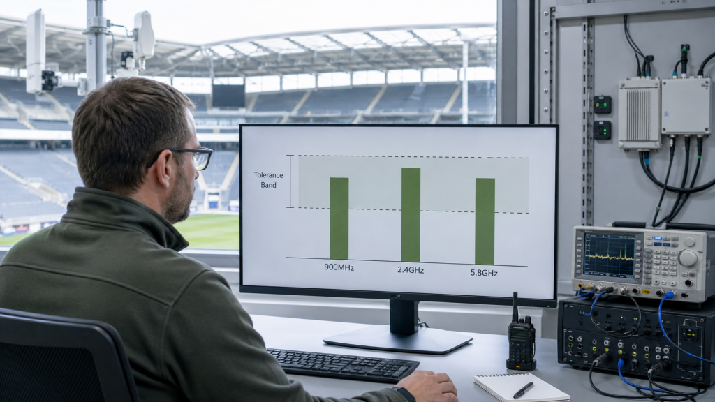
RF Power Consistency can still allow channel power variation when the difference is defined, measured at the same boundary, stable under load, and still meets the C-UAS system’s venue coverage requirement. Power consistency does not mean every frequency must show the exact same wattage. It means the system understands the difference and can explain it.
The practical risk is clear: unmanaged variation becomes a field problem, while defined variation becomes an engineering condition. A higher-frequency path, longer feeder route, or different antenna branch may reasonably show lower delivered power, but that difference should not surprise the acceptance team.
What Makes Variation Normal?
Some variation is normal because RF channels do not share identical conditions. Frequency, PA efficiency, feeder loss, connector path, antenna match, and module location can all change delivered power.
Acceptable variation is usually tied to:
- Defined channel tolerance
- Same measurement point
- Same operating temperature range
- Same duty-cycle condition
- Repeatable test method
- Stable protection status
- System-level coverage requirement
A channel does not have to match another channel perfectly, but it should remain predictable under the conditions that matter to the project.
When Does Variation Become a Risk?
Variation becomes a risk when it is discovered late, cannot be repeated, or cannot be traced to a known cause. If one channel looks normal at the PA port but weak at the antenna port, the team must identify whether the difference comes from the module, feeder, connector, antenna, supply, thermal state, or measurement method.
Key Takeaway: Channel variation is acceptable only when it is defined before acceptance and remains stable under the required multi-channel operating condition.
| Variation Condition | Acceptable? | Engineering Reason |
|---|---|---|
| Defined and repeatable | Yes | System can account for it |
| Same boundary comparison | Yes | Results are comparable |
| Unknown late-stage drop | No | Cause is unclear |
| Thermal drift after long duty | Risky | Venue operation may expose it |
| One channel enters protection | No | Output is no longer normal |
This table helps reviewers separate normal RF variation from unmanaged channel imbalance.
3. How to Define RF Power Consistency Across Channels
RF Power Consistency across channels means predictable output differences measured at the same boundary, under the same operating condition, and verified across both module-level and installed antenna-port conditions. It is not only a wattage comparison. It is a comparison method.
This is where system integrators should pay attention: if two channels are measured at different points, with different cable paths, under different thermal states, their numbers cannot be fairly compared. Before discussing “consistency,” the system must define what is being compared.
Which Boundaries Must Be Defined First?
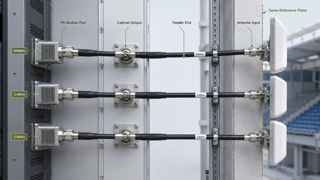
The measurement boundary must come before the power comparison. PA module port, cabinet output, feeder end, and antenna input are not the same point.
Before comparing channels, engineers should define RF power measurement points so PA-port output, cabinet output, feeder-end power, and antenna-port power are not mixed.
A useful boundary review should include:
- PA module output connector
- Cabinet output or bulkhead point
- Feeder-end reference point
- Antenna input reference point
- Coupler or meter location
- Loss compensation method
- Installed path condition
Which Operating Conditions Must Match?
The operating conditions must also match. If one channel is measured cold and another is measured after heat soak, the comparison is weak. If one channel runs alone and another runs during simultaneous multi-channel operation, the power result may reflect system load rather than module capability.
Key Takeaway: RF Power Consistency is meaningful only when the boundary, frequency, load, supply, temperature, duty cycle, and protection state are defined for every channel.
| Consistency Factor | What It Defines | Risk If Missing |
|---|---|---|
| Measurement point | Where power is valid | Boundary confusion |
| Operating temperature | Cold or hot-state output | Hidden thermal drift |
| Supply voltage | Module-side DC condition | Uneven channel output |
| Load and antenna path | Real RF condition | Wrong module diagnosis |
| Protection status | Whether output is limited | Misread channel weakness |
This table turns “power consistency” into a testable system requirement instead of a vague expectation.
4. How Does Channel Imbalance Affect C-UAS Performance?
RF Power Consistency affects C-UAS performance because channel imbalance can create frequency-dependent weak zones, uneven antenna-port power, and misleading diagnostics even when total rated power appears sufficient. In a large venue, system behavior is shaped by channel balance across zones, not only by the strongest channel.
Here’s the field reality: the system may look powerful in aggregate while one band, one antenna route, or one venue zone becomes the weak point. That weakness may not appear if the acceptance team only reviews total module wattage.

Where Can Imbalance Show Up?
Channel imbalance can appear as a frequency weakness, a zone weakness, or a time-based drift. In large venues, these problems may appear around entrances, rooflines, parking zones, stage-side temporary structures, or outer perimeters where feeder paths differ.
Possible symptoms include:
- One frequency band reads lower than the others
- One antenna zone shows lower antenna-port power
- High-band channels drop more after installation
- Output changes after all channels run together
- A channel enters VSWR or temperature protection
- Factory and venue retest results disagree
In Low-Altitude Security & C-UAS EW Solutions, multi-band output consistency matters because system performance depends on controlled antenna-port power, not only total rated wattage.
Why Does Imbalance Confuse Diagnostics?
Imbalance confuses diagnostics because the first suspicion often falls on the PA module. Yet the real cause may be feeder routing, antenna match, connector condition, voltage drop, cabinet heat, calibration, or the measurement boundary.
Key Takeaway: Channel imbalance matters because it can create system-level uncertainty even when every module appears to pass individual output testing.
| Symptom | Possible Cause | Better Starting Point |
|---|---|---|
| One band is weaker | Frequency-related loss | Check path and band data |
| One zone is weaker | Longer antenna route | Compare antenna-port power |
| Output falls after hours | Heat or supply load | Run long-duration test |
| VSWR alarm appears | Antenna or connector mismatch | Review load path |
| All channels read low | Reference-plane difference | Compare test setup |
This table helps engineers troubleshoot imbalance without blaming the wrong component first.
5. How to Check RF Power Consistency in Large Venues
RF Power Consistency problems become easier to detect in large venue deployments because multi-zone coverage, long feeder routes, multiple antenna arrays, high-frequency paths, and long event duty cycles amplify small channel differences. A stadium or urban venue is not a clean single-path RF environment.
The better check is simple: judge channel consistency in the installed venue context, not only in a factory module report. Venue geometry and temporary installation constraints often decide where the real imbalance appears.
Which Venue Conditions Create Imbalance?
Large venues may require multiple antenna zones to cover seating areas, entrances, rooftops, service corridors, outer perimeters, parking areas, or temporary event zones. Each zone can create a different RF path.
In a large venue C-UAS deployment, engineers should expect consistency pressure from:
- Unequal feeder length
- Different antenna heights
- Multiple cabinet locations
- Rooftop or perimeter routing
- Temporary cable paths
- Extra connectors or adapters
- High event-duty operation
- Limited maintenance windows
Different antenna routes create different RF Power Amplifier feeder and connector loss, which can make two channels look equal at the module port but unequal at the antenna port.
Why Does the Venue Case Matter?
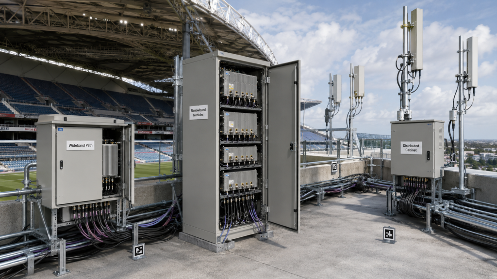
A venue case matters because the RF chain is exposed to real installation pressure. In a high-density urban venue, one cabinet may feed several zones, while another cabinet may serve a roof or perimeter route through a longer cable path. The Urban Shield venue security case shows why complex urban signal environments, long-duty operation, and distributed deployment conditions require more than a single output-power claim.
Key Takeaway: Large venues turn small module, cable, and antenna differences into system-level balance questions.
| Venue Condition | Consistency Risk | Better Check |
|---|---|---|
| Multiple antenna zones | Uneven delivered power | Compare antenna-port output |
| Long feeder routes | Higher path loss | Estimate route-specific loss |
| Temporary deployment | Adapter variation | Record final RF path |
| Rooftop antennas | Different cable exposure | Review installed path |
| Long event duty | Heat and supply drift | Run simultaneous long test |
This table helps venue teams connect physical layout to channel-to-channel power behavior.
6. Why Must Heat, Supply, Feeder, and Frequency Be Checked?
RF Power Consistency must be checked together with heat, supply voltage, feeder length, connector count, frequency behavior, and antenna-port conditions because channel imbalance rarely comes from one isolated cause. In a multi-band large venue system, several small differences can stack into one visible output gap.
This is where the selection risk appears: if you test these factors separately, each one may look acceptable. When all channels run together, the combined stress may reveal imbalance.
How Do Thermal and Supply Conditions Change Channels?
Thermal and supply conditions can affect channels differently. A module closer to a heat source may drift earlier. A channel connected through longer DC wiring may see lower module-terminal voltage under full load. If multiple PAs share the same 28V rail, one channel’s load can affect another channel’s output stability.
During long venue events, RF Power Amplifier ambient temperature can change channel balance because some modules may heat faster or derate earlier than others.
Check these conditions:
- Module temperature rise by channel
- Cabinet airflow path
- Shared or independent 28V supply
- Module-terminal voltage under full load
- Current draw per band
- Protection threshold behavior
- Output after heat soak
How Do Feeder and Frequency Effects Stack?
Feeder and frequency effects stack when high-frequency paths also use longer cable runs or more connectors. A 5.8GHz channel may face more path sensitivity than a lower-frequency channel, especially if the antenna location forces a longer route.
For RF Power Amplifier modules, wideband output, PCB layout, shielding structure, connector path, temperature protection, and repeatable test evidence should be reviewed together. This is where source-factory engineering support has value: the discussion is no longer only “how many watts,” but how each channel behaves under real electrical, thermal, RF, and installation conditions.
Key Takeaway: RF Power Consistency must be checked as a combined system result, not as separate thermal, DC, feeder, and frequency notes.
| Engineering Factor | How It Changes Consistency | What to Check |
|---|---|---|
| Heat | Some channels derate earlier | Hot-state output |
| Shared supply | Voltage drops under load | Module-terminal voltage |
| Feeder length | Antenna-port power differs | Route-specific loss |
| Frequency band | High band may lose more | Low/mid/high comparison |
| Connector count | Added transition loss | Channel path list |
This table helps engineers find stacked causes instead of treating channel imbalance as a single-part defect.
7. How Do RF Architectures Affect Channel Consistency?
RF Power Consistency depends on the chosen RF architecture because wideband, narrowband, modular, and distributed systems create different balance risks. No architecture automatically guarantees channel consistency. Each one needs a matching calibration and test method.
Here’s the practical point: architecture affects not only how many modules you buy, but also how many channels, paths, loads, feedback signals, and test boundaries must stay aligned.
How Do Wideband and Narrowband Paths Differ?
Wideband RF Power Amplifier modules can reduce module count and simplify cabinet architecture, but they require full-band output and flatness evidence. A channel near the edge of a wideband module may behave differently from a center-frequency point.
For wideband modules, RF Power Amplifier gain flatness and output flatness should be reviewed before assuming that all frequency channels behave consistently.
Narrowband modules may be easier to optimize for specific bands, but multiple narrowband modules can introduce batch variation, per-channel calibration differences, control differences, and thermal placement differences.
How Do Modular and Distributed Cabinets Change the Test?
Modular and distributed cabinets can help large venues by placing RF hardware closer to antenna zones. That may reduce feeder loss, but it also creates cross-cabinet consistency questions.
For verified wideband RF Power Amplifier performance, test evidence should include per-channel output, thermal behavior, voltage, current, load condition, and protection status.
Key Takeaway: Architecture choice changes the type of consistency evidence the buyer should request.
| Architecture Option | Consistency Benefit | Consistency Risk |
|---|---|---|
| Wideband module | Fewer RF blocks | Band-edge imbalance |
| Narrowband modules | Band-specific tuning | Module-to-module variation |
| Modular matrix | Flexible expansion | More calibration points |
| Distributed cabinet | Shorter feeder paths | Cross-cabinet variation |
| Shared antenna path | Simpler layout | Coupling and mismatch risk |
This table helps buyers choose test evidence that matches the selected RF architecture.
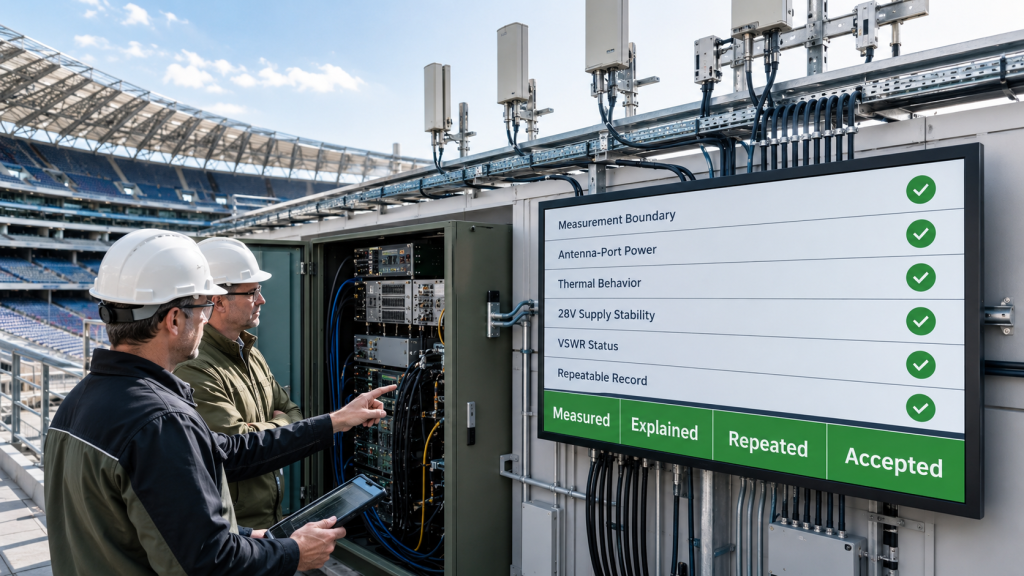
8. How to Prove RF Power Consistency With Test Evidence
RF Power Consistency should be verified with calibrated per-channel tests, simultaneous multi-channel operation, long-duration thermal checks, antenna-port measurements, protection feedback, and repeatable reports. A verbal claim that channels are “balanced” is not enough for a large venue C-UAS project.
The practical risk is clear: if the report does not show how each channel was measured, the field team cannot reproduce the result. That turns output imbalance into a supplier-customer argument instead of an engineering diagnosis.

What Evidence Should Be Included?
A useful power consistency file should prove both per-channel behavior and system-level behavior. Single-channel testing is necessary, but it is not sufficient.
The evidence should include:
- Channel map and frequency assignment
- Output reference point
- Per-channel output power
- Simultaneous multi-channel output
- Antenna-port measurement where required
- Supply voltage and current per test state
- Temperature by channel or cabinet area
- VSWR or reflected-power status
- Duty cycle and test duration
- Calibration and loss compensation notes
- S/N-linked module and channel record
If one channel drops after connecting the field antenna, engineers should review RF Power Amplifier VSWR protection before judging the module alone.
How Can Protection Feedback Explain Output Drops?
Protection feedback helps engineers decide whether a weak channel is truly weak or intentionally limited by the system. A channel may reduce output because of reflected power, high temperature, low voltage, over-current, or load instability. Without protection status, the output number tells only what happened, not why it happened.
As a source factory for RF Power Amplifier modules and C-UAS core components, RF SKYPOWER can connect module-side output data with channel structure, antenna-port targets, feeder-chain loss, thermal margin, 28V supply stability, VSWR / temperature / voltage protection feedback, and repeatable test evidence.
Key Takeaway: Test evidence should explain why a channel is strong, weak, stable, derated, or protected.
| Weak Evidence | Better Evidence | Why It Matters |
|---|---|---|
| One watt number | Boundary-defined output | Makes comparison fair |
| Single-channel pass | Simultaneous operation data | Shows system load |
| Cold output only | Hot-state output trend | Reveals event-duty risk |
| No protection status | VSWR and alarm record | Explains output drops |
| No channel map | Per-channel traceability | Supports retest |
| No S/N link | Unit-specific evidence | Reduces acceptance dispute |
This table helps procurement reviewers request evidence that supports field diagnosis, not only acceptance paperwork.
9. What RFQ Data Defines RF Power Consistency
RF Power Consistency can be quoted correctly only when the RFQ defines channels, bands, measurement boundaries, antenna layout, feeder paths, duty cycle, power tolerance, and test evidence requirements. If the RFQ only says “100W per band,” the supplier cannot judge multi-channel consistency.
This is where buyers should be specific. A good RFQ gives the supplier enough system context to evaluate channel balance before price and delivery are fixed.

What Should Be Shared Before Quotation?
Before quotation, engineers should provide a channel map rather than only a frequency list. The supplier needs to know how channels are assigned, where antennas sit, and how output will be judged.
Share these items:
- Required frequency bands
- Number of RF channels
- Output target per channel
- PA-port or antenna-port target
- Wideband or narrowband architecture preference
- Antenna count and location
- Feeder cable length per channel
- Connector, adapter, and lightning-protection count
- Cabinet quantity and location
- Shared or independent 28V power
- Expected event duty cycle
- Ambient temperature range
- Allowed channel-to-channel delta
- Required test report format
In large venues, antenna distance affects RF Power Amplifier selection because different feeder lengths can create channel imbalance across zones.
Why Is “Same Wattage Per Band” Not Enough?
Same wattage per band is not enough because the same number can refer to different boundaries. One buyer may mean module-port output, while the field team later tests antenna-port output. That mismatch can create a false failure even if the original quote was technically correct.
Key Takeaway: A good multi-band RFQ defines how consistency will be judged before the module, antenna, feeder, and cabinet decisions are locked.
| RFQ Item | Why It Matters | Risk If Missing |
|---|---|---|
| Channel map | Defines comparison groups | Confusing channel labels |
| Measurement boundary | Defines valid power point | PA-port vs antenna-port dispute |
| Feeder path | Explains delivered power | Hidden antenna-zone loss |
| Duty cycle | Shows heat and supply stress | Short-test approval only |
| Tolerance target | Defines acceptable difference | Subjective acceptance |
| Test report scope | Defines proof required | Unrepeatable result |
This table helps RFQ teams turn power consistency into a measurable purchasing requirement.
10. How Do You Decide If RF Power Consistency Is Enough?
RF Power Consistency is good enough only when each channel meets its defined boundary target, channel differences remain within the system tolerance, and installed antenna-port power stays predictable under simultaneous, long-duration operation. The goal is not absolute equality. The goal is controlled, explainable, repeatable balance.
Here’s the final decision point: if the system cannot explain why one channel differs from another, the consistency review is not finished.
What Decision Sequence Should Engineers Use?
Use a sequence that starts with the channel structure and ends with installed evidence. Do not start with the largest wattage number.
A practical decision sequence is:
- Define every channel, band, module, and antenna path.
- Define the measurement boundary for comparison.
- Verify each channel under standard conditions.
- Compare channel-to-channel output at the same boundary.
- Run simultaneous multi-channel operation.
- Check module-terminal voltage under load.
- Check thermal behavior after event-duty operation.
- Verify antenna-port power where required.
- Record VSWR, temperature, voltage, and alarm status.
- Confirm that factory, customer, and venue tests can be repeated.
When Should the System Be Adjusted?
The system should be adjusted when channel difference affects venue requirements or cannot be explained by a defined path, band, thermal, supply, or protection condition. The fix may not be a larger PA. It may be calibration, feeder optimization, antenna-layout change, improved supply margin, better cabinet airflow, channel reassignment, or architecture change.
As an RF Power Amplifier module and C-UAS core component source factory, RF SKYPOWER can support large venue projects by reviewing multi-band channel definition, output boundary, antenna path, feeder-chain loss, duty cycle, thermal condition, 28V supply behavior, protection feedback, and repeatable test reports before final approval. This moves the discussion beyond “how many watts per band” and toward real system-level RF Power Consistency.
Key Takeaway: Good power consistency means every channel can be measured, explained, repeated, and trusted under the installed venue condition.
| If the Problem Is… | Start With… | Avoid First |
|---|---|---|
| One channel is weak | Boundary and path check | Blaming the PA immediately |
| High band is lower | Frequency and feeder review | Comparing only center points |
| Output drops under load | Supply and thermal check | Replacing modules blindly |
| Venue zones differ | Antenna-port comparison | Using total power only |
| Retest data disagrees | Test setup comparison | Treating both tests as identical |
| Protection appears | VSWR, voltage, temperature status | Ignoring alarm evidence |
This table gives engineering and procurement teams a final path for deciding whether consistency is acceptable or needs correction.
FAQ
Can I judge a multi-band C-UAS system by total RF power?
No. Total RF power can hide weak channels. You should check per-channel output, antenna-port power, measurement boundary, simultaneous operation, thermal behavior, and protection status before judging RF Power Consistency.
What should I check before comparing RF channels?
Start with the measurement boundary. Then compare frequency, load, feeder path, supply voltage, thermal condition, duty cycle, calibration method, and protection status. Channels measured under different conditions should not be treated as directly comparable.
How do I know if channel imbalance is caused by the PA module?
You know only after checking the RF path. Review feeder length, connector count, antenna match, VSWR status, module-terminal voltage, thermal condition, and test boundary before treating the PA module as the cause.
What’s the best proof of multi-band RF Power Consistency?
The best proof is repeatable evidence showing per-channel output, simultaneous multi-channel output, antenna-port measurements where required, hot-state behavior, supply voltage, current, VSWR status, and S/N-linked test conditions.
When should I ask for antenna-port power consistency?
Ask for antenna-port power consistency when the venue uses long feeder routes, multiple antenna zones, rooftop antennas, distributed cabinets, high-frequency channels, or acceptance based on installed system performance rather than module-port data.
Conclusion
Multi-band C-UAS systems should not judge RF performance only by the rated output of each individual channel. A channel that passes module-level testing may still behave differently after feeder loss, connector count, antenna mismatch, cable length, thermal coupling, power supply load, cabinet position, and real venue installation are included. In large venue deployments, these differences can create frequency-dependent weak zones, uneven antenna-port power, and confusing field diagnostics.
For system integrators, RF engineers, and procurement reviewers, the practical lesson is clear: define channel structure first, then define measurement boundaries, test each channel, compare channel-to-channel output, verify simultaneous operation, check antenna-port power, record protection status, and confirm long-duration consistency under real deployment conditions.
RF SKYPOWER supports multi-band C-UAS RF Power Amplifier selection by reviewing channel structure, output consistency, antenna-port power, feeder-chain loss, thermal margin, supply stability, protection status, and repeatable test evidence before final project approval. If your large venue C-UAS project has not confirmed channel structure, antenna-port power, feeder loss, thermal margin, and protection status, you can review your multi-band RF Power Amplifier consistency with a source-factory engineering team before final approval.
If you want to align multi-band RF output, antenna-port evidence, feeder path assumptions, and protection feedback before quotation, you can also discuss your project with RF SKYPOWER before the venue layout becomes expensive to change.
Field-ready multi-band C-UAS performance starts with verified channel consistency, not a stack of isolated wattage claims.