


Antenna distance affects RF Power Amplifier selection because the physical gap between the module and the antenna becomes feeder length, and feeder length changes the power that actually reaches the antenna port. A module rated at 100W or 200W at its RF output connector may not deliver the same usable power at the antenna input after long cable runs, connector chains, adapters, cabinet feedthroughs, waterproof joints, or outdoor routing.
This matters in real C-UAS projects because antennas are often placed where coverage requires them, not where the amplifier cabinet is easiest to install. You may have rooftop antennas, tower-mounted antennas, vehicle-roof antennas, airport perimeter antennas, or remote mast antennas near protected assets. In low-altitude security and C-UAS system integration, RF Power Amplifier Selection should start from the installed RF chain, not only the amplifier label.
The practical question is simple: is the target wattage required at the module output, the cabinet output, the feeder end, or the antenna input? If that point is not defined early, the selected amplifier may look correct on paper but underpowered in the field.
1. What Drives RF Power Amplifier Selection First
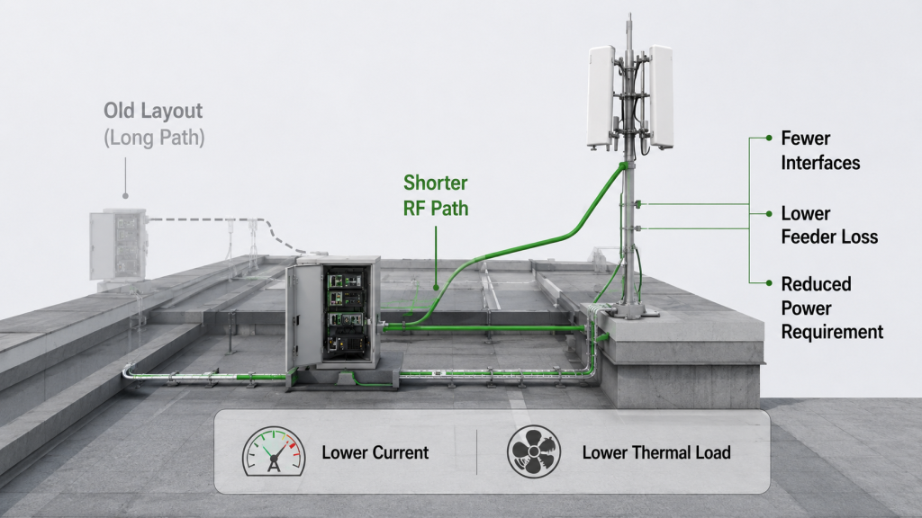
Antenna distance comes before RF Power Amplifier Selection because it decides how much RF path exists between the amplifier output and the antenna input. If you choose the module first and only later learn that the antenna must sit on a rooftop, tower, vehicle roof, or far-side perimeter pole, the original output power target may no longer match the installed system.
Here’s the engineering point: the amplifier output connector is not the end of the system. Power must pass through feeder cable, connectors, possible adapters, weatherproof joints, cabinet interfaces, and the antenna feed point before radiation begins. In an airport counter-UAS RF deployment, this matters because perimeter antennas may sit far from indoor equipment while still requiring predictable antenna-port power.

What Should Be Confirmed First?
You should confirm the antenna position before final module approval because physical layout changes the RF chain budget.
- Antenna distance from amplifier or cabinet
- Estimated feeder cable length
- Cable route, bends, and cabinet exits
- Connector and adapter count
- Target power reference point
- Outdoor exposure and maintenance access
Key Takeaway: Antenna distance is not a late installation detail. It is a selection parameter that helps you avoid choosing a module that is strong at the output port but weak at the antenna input.
| Early Question | Why It Matters | Selection Impact |
|---|---|---|
| Where is the antenna mounted? | Defines physical RF path | Changes feeder length |
| How long is the cable route? | Adds insertion loss | Changes power margin |
| What is the target power point? | Defines acceptance standard | Prevents wrong wattage choice |
| How many interfaces exist? | Adds loss and reflection risk | Affects protection behavior |
This table shows why antenna distance must be discussed before price, wattage, and final BOM approval.
2. How to Check RF Power Amplifier Selection by Loss
Feeder loss changes RF Power Amplifier Selection because antenna-port power is lower than module output power after RF energy passes through cable and interface loss. If you need 100W at the antenna input, a 100W module at the output connector may not be enough once the installed path consumes part of the power.
The practical risk is clear: two people may both say “100W” while referring to different points in the RF chain. One person may mean amplifier output power; another may mean antenna input power. That difference can cause field acceptance problems even when the amplifier itself is working normally. For a deeper check of installed cable behavior, engineers should review RF Power Amplifier feeder cable loss before judging the module.

What Is the Simple RF Chain Logic?
A useful selection discussion should treat the feeder path as part of the power system, not as a neutral wire.
- Module output power
- Cable insertion loss
- Connector and adapter loss
- Cabinet feedthrough loss
- Antenna input power
- Site-level coverage behavior
Key Takeaway: Feeder loss does not reduce the module’s rated port output, but it can reduce the power that reaches the antenna. You need both numbers before deciding whether the module size is correct.
| Power Point | What It Shows | Common Mistake |
|---|---|---|
| Module output | Amplifier capability | Treated as field power |
| Cabinet output | System interface power | Cable path ignored |
| Feeder end | Cable delivery result | Mistaken for module weakness |
| Antenna input | Installed RF result | Not defined before RFQ |
This comparison prevents false blame between module performance and installation-path loss.
3. How to Add Margin to RF Power Amplifier Selection
Higher frequency bands are more sensitive to RF Power Amplifier Selection because the same antenna distance can create more visible feeder loss at higher frequencies. A cable run that looks acceptable at 400MHz may become a serious power-delivery issue near 2.4GHz, 5.8GHz, or other high-frequency channels.
This is where system integrators should pay attention: distance cannot be separated from frequency. After choosing the correct RF Power Amplifier frequency range, you still need to check whether antenna distance and feeder loss allow enough antenna-port power across the required band. A one-point center-frequency estimate can hide band-edge or high-band weakness.

Which Bands Need More Care?
You do not need to treat every band the same. Higher bands usually deserve stricter feeder-path review.
- Low bands may tolerate longer routes better
- Mid bands need cable-grade review
- High bands need shorter or lower-loss paths
- Wideband systems need band-by-band checking
- Remote high-band antennas need extra margin
Key Takeaway: Higher frequency channels can become the first weak point in a long antenna run. This helps you avoid selecting all channels by one comfortable low-frequency assumption.
| Frequency Situation | Distance Sensitivity | Engineering Response |
|---|---|---|
| Low band | Lower | Confirm cable loss normally |
| Mid band | Moderate | Check cable grade and route |
| High band | Higher | Shorten path or add margin |
| Wideband system | Uneven | Verify across full band |
The key is not to avoid high bands, but to prove that the installed path still supports them.
4. How Do Long Antenna Runs Affect Power Margin?
Long antenna runs affect RF Power Amplifier Selection by consuming power margin before RF energy reaches the antenna input. If the module is selected exactly at the target wattage with no allowance for feeder loss, connector loss, heat, or field routing, the antenna side may fall below the required level.
Here’s the field reality: increasing the module power is not the only answer. A long cable path may justify a larger amplifier, but it may also justify lower-loss cable, fewer adapters, a different cabinet location, or a distributed RF layout. If the chosen module power increases, you must also recheck 28V DC supply capacity, current reserve, thermal design, airflow, and protection behavior.

What Changes When Margin Is Consumed?
Power margin links RF planning with mechanical, electrical, and thermal design.
- More output power may mean more current
- More current may require stronger DC cabling
- More RF power increases thermal load
- Higher duty cycle raises cooling pressure
- More interfaces increase reflected-power risk
- Field retesting becomes more important
Key Takeaway: Long antenna runs can make a larger module necessary, but they also create system-level costs. A good selection process compares amplifier size with layout and feeder-path improvement.
| Design Choice | Benefit | Trade-Off |
|---|---|---|
| Larger amplifier | More compensation power | More heat and current |
| Lower-loss feeder | Less antenna-side loss | Higher cable cost and stiffness |
| Shorter RF path | Better delivery efficiency | May change cabinet layout |
| Distributed RF unit | Reduces long feeder paths | Adds outdoor protection needs |
This is why power margin should be reviewed with the full RF chain, not only the amplifier model.
5. Can Antenna Distance Change Wideband and Narrowband Choices?
Antenna distance can change RF Power Amplifier Selection because wideband and narrowband choices behave differently once feeder loss is added to the RF chain. A wideband module may support multiple bands, but long antenna paths can make frequency-dependent loss and full-band proof more important.
This is where module selection becomes more than a datasheet comparison. When selecting wideband and narrowband RF Power Amplifier modules, you should review antenna distance, feeder length, frequency band, antenna-port power, and duty cycle together. RF SKYPOWER’s source-factory engineering support is useful here because the discussion can include module output, feeder path, VSWR protection, thermal condition, and repeatable test data in one chain.

What Should You Compare?
The choice is not simply “wideband is better” or “narrowband is stronger.” The right answer depends on the installed path.
- Wideband modules need full-band output evidence
- Narrowband modules still need path-loss review
- Long feeders can expose high-band weakness
- Multi-antenna systems may need channel-specific planning
- Duty cycle and cooling must match the selected power level
Key Takeaway: Antenna distance makes wideband and narrowband selection more dependent on real RF-chain behavior. You should evaluate delivered antenna power, not only module coverage labels.
| Module Choice | Distance Concern | What to Verify |
|---|---|---|
| Wideband module | Uneven feeder loss across band | Full-band output evidence |
| Narrowband module | Specific channel may use long cable | Channel loss budget |
| Multi-module system | Different antenna routes | Per-channel path review |
| Remote antenna layout | More interfaces and exposure | VSWR and protection response |
This keeps the article focused on selection, not a generic wideband-versus-narrowband debate.
6. What Data Helps RF Power Amplifier Selection
Gain flatness and output flatness matter more in RF Power Amplifier Selection when antennas are remote because feeder loss can make weak frequency points even weaker at the antenna port. A module may look acceptable at a center frequency, yet still deliver poor antenna-side power near a band edge after a long cable run.
Here’s the practical risk: module variation and cable variation can stack. If one frequency point already has lower gain or lower output, and the feeder path also loses more energy at that frequency, the antenna input may show a larger drop than expected. That is why RF Power Amplifier gain flatness becomes more important in remote antenna layouts.

What Evidence Should Buyers Ask For?
You should ask for data that reflects the band and field condition, not only one strong test point.
- Full-band sweep data
- Gain flatness report
- Output flatness comparison
- Test frequency points near band edges
- DC voltage and current during test
- Load condition and test duration
- Temperature and protection status
Key Takeaway: Remote antennas make full-band consistency more important because cable loss can magnify weak points. This helps buyers avoid approving a wide frequency label without enough proof.
| Evidence Type | What It Shows | Why It Matters |
|---|---|---|
| Gain flatness | Amplification consistency | Finds weak frequency zones |
| Output flatness | Delivered RF power consistency | Shows usable output variation |
| Full-band sweep | Behavior across range | Avoids one-point approval |
| Thermal data | Stability under load | Links RF output to real duty |
This table separates real verification from a simple peak-power claim.
7. How Does Antenna Distance Affect VSWR and Protection?
Antenna distance affects RF Power Amplifier Selection because longer antenna paths create more places where mismatch, loose contact, water ingress, bending, adapter errors, or feed-point problems can appear. The distance itself does not create VSWR, but the longer installed path often makes reflected-power diagnosis harder.
This is where system integrators should slow down before blaming the amplifier. If reflected power appears after remote antenna installation, engineers should prevent RF Power Amplifier field failure from antenna mismatch by checking the complete path from module output to antenna feed point. VSWR protection is a module safeguard; it is not automatically proof that the amplifier is defective.

What Should Be Checked First?
Protection behavior should be interpreted through the whole RF path.
- Module output connector
- Cabinet RF interface
- Feeder cable condition
- Adapter and connector torque
- Waterproof joints
- Surge or lightning protection device
- Antenna feed point
- Antenna match after installation
Key Takeaway: Remote antennas make VSWR alarms harder to interpret. A clear check sequence helps you protect the module while finding the actual RF-path problem.
| Possible Issue | Field Symptom | First Check |
|---|---|---|
| Loose connector | Reflected power alarm | Retighten and retest |
| Wet outdoor joint | Intermittent alarm | Inspect sealing |
| Bent feeder section | Power drop or mismatch | Check cable route |
| Poor antenna match | VSWR protection trigger | Test antenna and feed point |
The point is not to disable protection, but to understand what the protection is telling you.
8. How Can Layout Reduce Required RF Amplifier Power?
Layout can reduce required RF Power Amplifier Selection by shortening feeder paths, reducing avoidable loss, and placing RF energy closer to the antenna input. In many projects, the best solution is not simply a larger amplifier; it is a cleaner RF layout.
Here’s the engineering point: every meter of high-power RF path and every extra interface should justify itself. For critical infrastructure Counter-UAS deployment, antenna distance, feeder routing, module power margin, and protection status should be reviewed before final amplifier approval because maintenance access and long-term stability matter as much as initial output.
What Layout Choices Help Most?
Good layout reduces the power that must be compensated at the module output.
- Move the RF module closer to the antenna where practical
- Use lower-loss cable for long runs
- Reduce unnecessary adapters
- Keep high-frequency paths shorter
- Balance cable lengths in multi-antenna systems
- Protect outdoor RF units from heat, water, dust, and vibration
Key Takeaway: Better layout can reduce the need for higher module power. This helps you control heat, current demand, cost, and long-term service risk.
| Layout Option | Benefit | Condition to Check |
|---|---|---|
| Shorter feeder path | Less RF loss | Cabinet location |
| Lower-loss cable | More antenna-side power | Bend radius and cost |
| Fewer adapters | Lower loss and mismatch risk | Connector compatibility |
| Distributed RF unit | Short RF path | Outdoor protection and power |
This is the section that prevents the article from becoming “long cable means bigger amplifier.”
9. What to Share Before RF Power Amplifier Selection
Antenna distance details should be shared before RF Power Amplifier Selection because the supplier cannot judge real field loss from frequency and wattage alone. Even if the final installation drawing is not ready, you should provide a practical range so the module, feeder path, and test conditions can be discussed together.
This is where procurement and engineering need the same language. In a high-duty C-UAS RF output scenario, remote antennas and long feeder paths should be evaluated before deciding whether each RF channel has enough antenna-port power. The RFQ should define what “enough power” means and where that power must be measured.
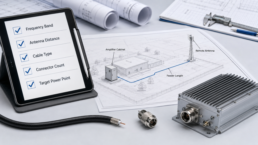
What Should the RFQ Include?
A useful RFQ does not need perfect final drawings, but it should include enough RF-chain context.
- Target frequency bands
- Target power reference point
- Approximate antenna distance
- Estimated feeder length
- Cable grade or planned cable type
- Connector and adapter count
- Outdoor or indoor routing
- Antenna mounting position
- Duty cycle and operation time
- Required test report conditions
Key Takeaway: Sharing antenna distance before quotation helps the supplier size the amplifier from real field need, not from an isolated wattage request.
| RFQ Detail | Why It Matters | Result |
|---|---|---|
| Antenna distance | Defines path length | Better power estimate |
| Target power point | Defines acceptance | Avoids wattage confusion |
| Cable type | Determines loss | Improves chain budget |
| Duty cycle | Affects heat | Supports reliable selection |
This checklist keeps early quotation practical without turning RFQ into a construction contract.
10. How to Size RF Power Amplifiers by Distance
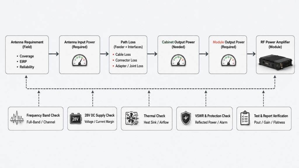
You should select RF Power Amplifiers for remote antennas by starting from antenna-port power, adding real feeder-chain loss, then confirming module output, thermal capacity, supply margin, and protection behavior. RF Power Amplifier Selection should move backward from field requirement to module requirement, not forward from a clean module label.
Here’s the field reality: a remote antenna layout affects power, frequency response, protection, thermal load, DC supply, and test reporting at the same time. For verified wideband RF Power Amplifier performance, remote antenna layouts should be reviewed because cable loss, reflected power, heat, and control limits appear together in real deployment.
What Selection Flow Works Best?
A practical selection flow should be simple enough for RFQ review but strict enough for field acceptance.
- Define the target power point
- Confirm antenna position and distance
- Estimate actual feeder length
- Check loss by frequency band
- Add connector and interface loss
- Decide module output power and margin
- Recheck 28V supply and current reserve
- Recheck heat sink, airflow, and duty cycle
- Confirm VSWR, temperature, and voltage protection
- Request repeatable test data
Key Takeaway: Remote antenna selection is a reverse calculation from antenna requirement to module capability. This protects you from approving the wrong wattage, the wrong feeder path, or the wrong test condition.
| Selection Step | Main Question | Approval Output |
|---|---|---|
| Define target point | Where must power be guaranteed? | Clear acceptance point |
| Calculate path loss | What does the feeder chain consume? | Required module output |
| Check frequency behavior | Which band is most sensitive? | Band-specific margin |
| Verify system limits | Can power, heat, and protection support it? | Safer final approval |
This selection process turns antenna distance into an engineering parameter instead of a late-stage surprise.
FAQ
Can I use a 100W RF Power Amplifier if I need 100W at the antenna?
Not always. If you need 100W at the antenna input, the module output may need to be higher than 100W because feeder cable, connectors, adapters, and cabinet interfaces can consume part of the RF power.
What’s the best way to reduce power loss from long antenna cables?
The best first step is to shorten or simplify the RF path where possible. You can also use lower-loss cable, reduce adapter chains, improve connector quality, and place RF modules closer to antennas when the site allows it.
How do I know if weak field power comes from the module or cable path?
Test at multiple points. Compare module output, cabinet output, feeder end, and antenna input under the same frequency, voltage, load, and measurement conditions.
Can I solve long antenna distance by choosing a bigger amplifier?
Sometimes, but not always. A larger amplifier may compensate for loss, but it also increases current demand, heat load, cabinet pressure, and protection risk, so layout and cable improvements may be better.
What’s the best RFQ information to send before selection?
Send frequency band, target power reference point, antenna distance, feeder length, cable type, connector count, duty cycle, installation scenario, and required test conditions. That gives the supplier enough context to size the module properly.
Conclusion
Antenna distance changes RF Power Amplifier Selection because it changes the installed RF chain between the module output and the antenna input. This article showed why antenna distance must be confirmed before module approval, how feeder loss changes antenna-port power, why high-frequency bands are more sensitive, how long runs consume power margin, and why gain flatness, output flatness, VSWR protection, and layout all become more important with remote antennas.
For system integrators, RF engineers, and procurement reviewers, the practical lesson is clear: do not approve an RF Power Amplifier only by target wattage. Define whether the power requirement belongs at the module output, cabinet output, feeder end, or antenna input. Then review feeder length, cable grade, connector count, frequency band, duty cycle, supply margin, thermal condition, and protection behavior.
RF SKYPOWER can support RF Power Amplifier module selection by reviewing antenna distance, feeder length, target antenna-port power, frequency band, wideband or narrowband choice, duty cycle, thermal condition, and C-UAS integration scenario before final approval. If your project has not confirmed these details, you can review your RF Power Amplifier antenna distance with a source-factory engineering team before final approval.
A reliable C-UAS RF chain is not built from isolated wattage numbers; it is built from controlled power delivery from module output to antenna input.