










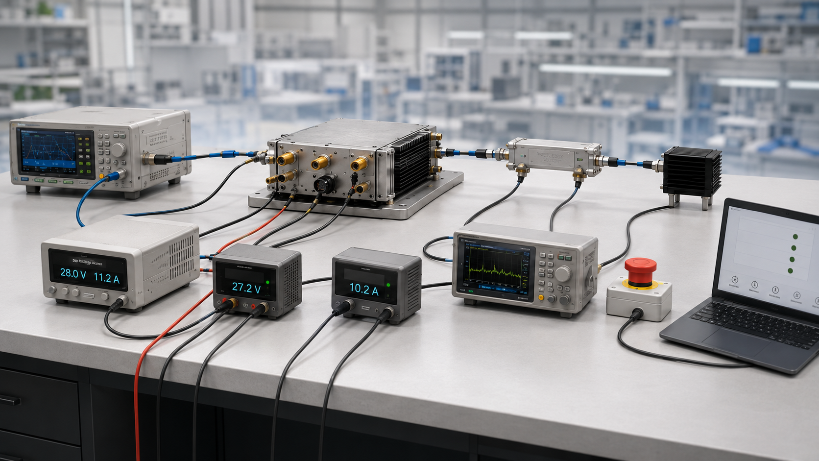
An RF PA can pass output-power testing and still fail system acceptance if its protection behavior is unclear. A warning may never reach the controller, foldback may look like weak gain, shutdown may occur without fault identity, or automatic recovery may create a repeated restart loop.
The question is not only whether the module lists VSWR, thermal, voltage, and current protection. The real question is whether each abnormal condition produces a defined trigger, RF response, alarm state, recovery rule, and repeatable test result.
Before approving RF Power Amplifier Modules, validate the complete protection state machine under controlled RF, load, DC, and thermal conditions. The acceptance record should show what was detected, what the PA did, what the controller reported, and how the affected channel returned to service.
1. What RF PA Protection Logic Must Prove Before Acceptance
RF PA protection logic is the complete behavior between the first abnormal condition and the final approved return to normal operation.
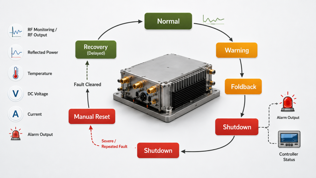
A module may include several protection functions, such as:
- Reflected-power or VSWR protection
- Over-temperature protection
- Under-voltage protection
- Over-voltage protection
- Over-current protection
- Output foldback
- RF shutdown
- Latched fault
- Automatic recovery
- Manual Reset
- Fault or alarm feedback
The presence of these functions in a datasheet does not prove that the protection system is acceptable.
Acceptance should prove five things:
- Detection: The PA identifies the correct abnormal condition.
- Response: The PA reduces or disables RF output as defined.
- Visibility: The controller receives the correct alarm or status.
- Recovery: The PA returns to service only under the approved rule.
- Repeatability: The same controlled event produces results within the approved tolerance.
Protection behavior should also match the system-level RF PA control logic. A module can respond internally while the wider system still behaves incorrectly because the controller interprets the alarm, Reset, or recovery state differently.
Protection is not a single threshold
Protection is often described with one value:
- Maximum temperature
- Maximum reflected power
- Minimum voltage
- Maximum current
A real protection state machine is more complex and may follow different paths depending on the fault category.
A typical structure may include:
Normal
→ Warning
→ Foldback
→ Shutdown
   ├─ Fault cleared → Delayed automatic recovery
   └─ Severe or repeated fault → Latched fault
                                  → Fault cleared
                                  → Approved manual Reset
                                  → Normal operation
The exact path depends on the approved control logic. Not every event should pass through every state.
For example:
- A mild thermal rise may produce only a warning.
- A moderate reflected-power condition may trigger foldback without shutdown.
- Severe over-voltage may cause immediate shutdown.
- A repeated fault may enter a latched state instead of automatic recovery.
- Some modules expose only Alarm and RF Disable.
- Other modules provide detailed warning, fault, telemetry, and recovery states.
The acceptance plan should use only the states supported by the actual interface, but every available state should have a documented meaning, expected action, and test result.
2. How to Define the Fault State Map and Pass Criteria
Protection testing should begin with a written state map, not with an uncontrolled attempt to force a failure.
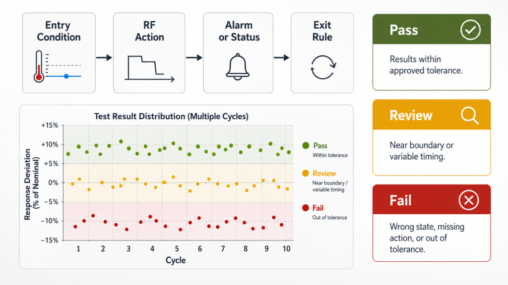
The state map explains:
- What condition enters each state
- What happens to RF output
- What alarm or status becomes active
- Whether the fault is latched
- What allows the PA to recover
- Whether Reset is required
- What result counts as Pass, Review, or Fail
RF PA Protection State Map
| State | Entry Condition | Expected RF Action | Alarm or Status | Exit Rule | Pass Criterion |
|---|---|---|---|---|---|
| Normal | All monitored conditions are valid | Target RF output allowed | Normal or Ready | A monitored limit is crossed | Stable output and no false alarm |
| Warning | Early boundary is crossed | Output remains unchanged or follows the documented early-response rule | Fault-specific warning | Condition clears or becomes more severe | Correct warning identity and timing |
| Foldback | Approved stress level is reached | Controlled reduction in RF output | Foldback or fault status | Stress returns below the recovery boundary | Predictable and repeatable Pout reduction |
| Shutdown | Severe condition is reached | RF output disabled | Shutdown alarm | Fault clears and the approved recovery rule becomes valid | Safe output removal without uncontrolled restart |
| Latched Fault | Severe or repeated event occurs | RF remains inhibited | Latched fault status | Fault condition clears, followed by an approved manual Reset or service action | No automatic restart before authorization |
| Recovery Eligible | Fault has cleared | Output remains off or returns in stages | Recovery or Ready status | Delay, Reset, or approved sequence completes | Stable return without repeated fault |
| Normal After Recovery | Approved restart is complete | Target output restored | Normal status | A new fault occurs | Output and status return to the approved baseline |
Define Pass, Review, and Fail
A useful acceptance plan should not use only Pass or Fail.
Pass
- Trigger occurs inside the approved tolerance
- RF response matches the state map
- Fault identity is correct
- Controller receives the event
- Recovery follows the approved rule
- Repeated testing remains inside the approved spread
Review
- Trigger occurs near the tolerance boundary
- Alarm identity is correct, but response timing varies
- Recovery is successful, but delay differs between runs
- Output returns, but post-recovery drift requires analysis
- Different units show wider-than-expected response variation
Fail
- Protection does not trigger
- Wrong fault identity is reported
- RF output remains active during a shutdown condition
- The PA enters an uncontrolled restart loop
- Recovery occurs before the fault clears
- One channel Reset incorrectly clears another channel’s fault
- The test cannot be repeated within the approved tolerance
Define tolerance and repeatability before testing
“Repeatable” should not be judged only by visual similarity between two tests.
The acceptance plan should define:
- Permitted trigger-value spread
- Response-time tolerance
- Foldback-level tolerance
- Shutdown-delay tolerance
- Recovery-delay tolerance
- Post-recovery output tolerance
- Required number of repeated cycles
- Allowed unit-to-unit spread
- Pass, Review, and Fail boundaries
These values should be tied to the actual module model, serial number, hardware version, firmware version, frequency, output level, cooling condition, and test method.
3. How to Test Trigger, Foldback, Shutdown, and Latch Behavior
Protection validation should use authorized, controlled, and properly instrumented laboratory conditions.
It should not create uncontrolled high VSWR, unsafe over-voltage, excessive current, or thermal stress beyond the approved test boundary. The goal is to verify behavior, not to damage the module.
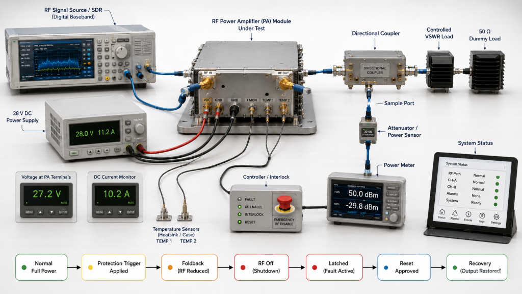
Qualified personnel should define:
- Approved test range
- RF load
- Input drive
- Frequency
- Output target
- DC voltage and current limits
- Cooling condition
- Maximum test duration
- Instrument ratings
- Emergency shutdown method
- Abort conditions
Define test-abort conditions
Stop the test when:
- Temperature exceeds the approved boundary
- Vdc or Idc leaves the authorized range
- Unexpected oscillation or unstable RF output appears
- The RF load or instrument approaches its rating
- Alarm identity does not match the applied condition
- The DC source enters uncontrolled current limiting
- The module does not respond to the emergency shutdown method
- Connector, cable, or load heating becomes abnormal
- A repeated restart loop begins
- Continuing the test may damage the PA or test equipment
Protection Validation Matrix
| Fault Branch | Controlled Input Condition | Expected RF Action | Required Status | Recovery Check |
|---|---|---|---|---|
| Reflected power | Defined mismatch or reflected-power boundary | Warning, foldback, or shutdown | VSWR or reflected-power fault | Approved load restored |
| Thermal | Controlled temperature rise within the authorized boundary | Warning, derating, or shutdown | Thermal warning or fault | Temperature falls below the recovery boundary |
| Under-voltage | Defined module-terminal voltage reduction | Warning, RF inhibit, or shutdown | Under-voltage status | Valid Vdc restored |
| Over-voltage | Controlled supplier-approved voltage event | RF inhibit or shutdown | Over-voltage status | Voltage returns to the approved range |
| Over-current | Supplier-approved operating or test condition that activates the documented internal current-protection branch without forcing uncontrolled external supply limiting | Current limit, RF mute, or latch | Over-current status | Root cause removed and Reset rule followed |
| Repeated fault | Approved event repeated at defined intervals | Retry limit or latched shutdown | Fault count or latched status | Manual review or approved Reset |
Verify trigger behavior
For each branch, record:
- Fault type
- Applied condition
- Trigger value
- Trigger tolerance
- Frequency
- Input drive
- PA-port output before the event
- Vdc and Idc
- Temperature
- Forward and reflected power
- Controller timestamp
- RF response time
- Alarm response time
A protection event should not be judged from only one display.
For reflected-power testing, compare:
- Forward power
- Reflected power
- Calculated or measured VSWR
- PA output response
- Reported fault identity
Detailed antenna-chain and load risks should remain in the separate article on RF PA VSWR field failures. This article uses VSWR only as one controlled protection-validation branch.
Verify foldback behavior
Foldback should produce a controlled and explainable reduction in RF output.
Record:
- Output before foldback
- Output during foldback
- Input drive
- Current change
- Temperature or reflected-power condition
- Alarm state
- Whether output reduction is smooth or abrupt
- Whether repeated cycles remain within tolerance
Foldback should not be confused with:
- Insufficient input drive
- DC voltage drop
- Gain compression
- Thermal drift without a protection state
- Cable or adapter loss
- Measurement reference-plane error
A repeatable foldback response should occur only when the documented condition is present.
Verify shutdown behavior
A shutdown test should confirm:
- RF output is removed
- The correct fault is reported
- The controller records the event
- The PA remains in the intended state
- No unexpected RF pulse appears during recovery
- The channel does not restart before the approved condition is met
The test should also show whether shutdown affects:
- One RF channel
- One PA module
- A shared power rail
- A complete multi-channel group
- The RF source or SDR
- Cooling or control equipment
Verify latched-fault behavior
A latched fault should remain active after the triggering condition clears until the defined release action occurs.
Check whether release requires:
- Manual Reset
- Remote Reset
- DC power cycle
- Controller authorization
- Service action
- A defined cooling period
- A defined load correction
Do not accept a Reset that clears the latch while the original fault remains present.
Do not confuse over-current and under-voltage behavior
Internal over-current protection should not be validated only by reducing the external power-supply current limit.
That method may force the supply into current limiting, collapse the module-terminal voltage, reduce RF output, and trigger under-voltage behavior instead of the intended internal current-protection branch.
Over-current validation should use a supplier-approved condition and should record:
- Module-terminal Vdc
- Module Idc
- External supply state
- PA output
- Internal fault identity
- Controller status
- Recovery behavior
4. How to Verify Alarm, Status, Reset, and Recovery
Protection is incomplete if the PA reacts internally but the controller cannot understand what happened.
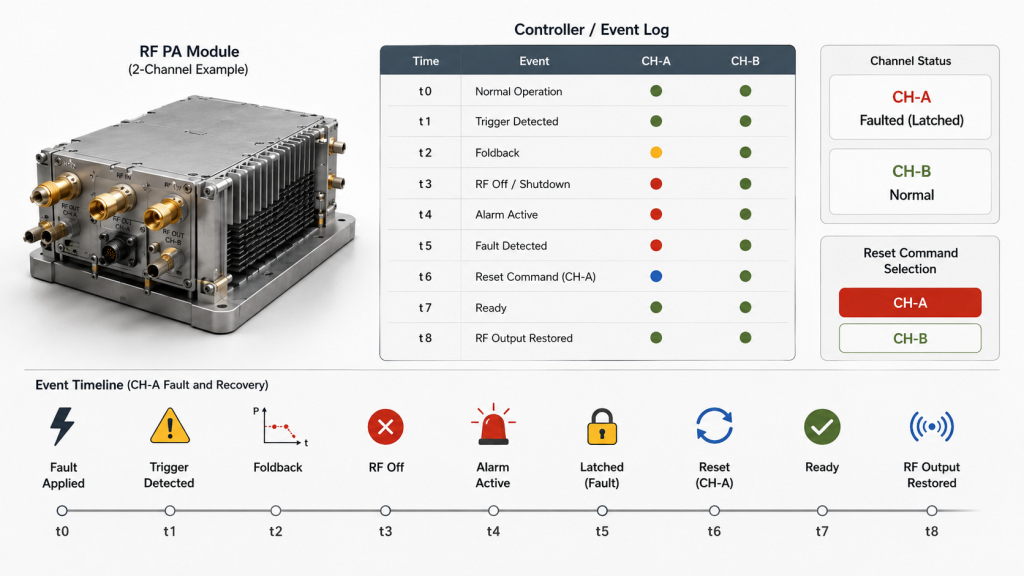
The control side should be able to determine:
- Which module faulted
- Which channel was affected
- Which fault category occurred
- When the event occurred
- Whether output was reduced or disabled
- Whether the fault remains active
- Whether Reset is allowed
- Whether recovery is complete
Verify alarm identity
A general Alarm output may be acceptable for a simple design, but it provides less diagnostic value than fault-specific status.
Where supported, distinguish:
- Reflected-power fault
- Thermal warning
- Thermal shutdown
- Under-voltage
- Over-voltage
- Over-current
- Communication fault
- Internal hardware fault
- Recovery in progress
The reported alarm should match the applied test branch.
Check alarm polarity and interface state
Incorrect interface interpretation can make a valid protection response appear missing or permanently active.
Verify:
- Active-high or active-low alarm polarity
- Open-drain or push-pull output type
- Pull-up or pull-down location
- Default state during controller boot
- Signal level at the PA connector
- Input debounce time
- Alarm sampling interval
- Whether the input floats during startup or cable disconnection
A correct internal protection response can still appear incorrect if the controller reads the alarm signal with the wrong polarity or reference.
Verify timing and status updates
Record the sequence:
Fault condition applied
→ Protection trigger detected
→ RF action begins
→ Alarm or status changes
→ Controller records event
→ Fault condition removed
→ Recovery condition becomes valid
→ Reset or automatic recovery begins
→ Ready returns
→ RF output returns
Not every interface exposes all these stages. Use only the states supported by the module, but confirm that each available state appears in the correct order.
Check for:
- Delayed alarm reporting
- Cached status
- Wrong channel identity
- Missing Ready state
- Alarm clearing before the fault clears
- Reset accepted but not completed
- Controller timeout shorter than recovery time
Verify Reset behavior
Reset should clear a latched state only after the approved recovery conditions are valid.
Test:
- Reset while the fault is still present.
- Reset after the fault clears.
- Reset while Enable remains active.
- Reset with Enable inactive.
- Repeated Reset commands.
- Reset after several fault events.
- Reset one channel while another channel remains faulted.
In a multi-module system, verify that:
- Resetting one channel does not clear another channel’s fault
- One module’s alarm does not lose its identity
- Shared status does not overwrite per-channel data
- Group Reset follows the approved system rule
- Unaffected channels remain in the correct state
Verify automatic recovery
Automatic recovery may be suitable for some conditions, but not every fault should restart automatically.
Review:
- Recovery delay
- Number of retries
- Back-off between retries
- Maximum retry count
- Transition to latched shutdown
- Controller notification
- Output level after restart
- Other-channel response during recovery
An uncontrolled loop such as:
Fault
→ Shutdown
→ Automatic Restart
→ Same Fault
→ Shutdown
→ Automatic Restart
should not be accepted as successful recovery.
Thermal warning, foldback, shutdown, and recovery behavior should also be compared with the dedicated RF PA thermal alarm review when the event is driven by temperature rise.
5. What Can Create a False Protection Pass or Failure
Protection testing can produce the wrong conclusion when the test setup, measurement boundary, or control data is incorrect.
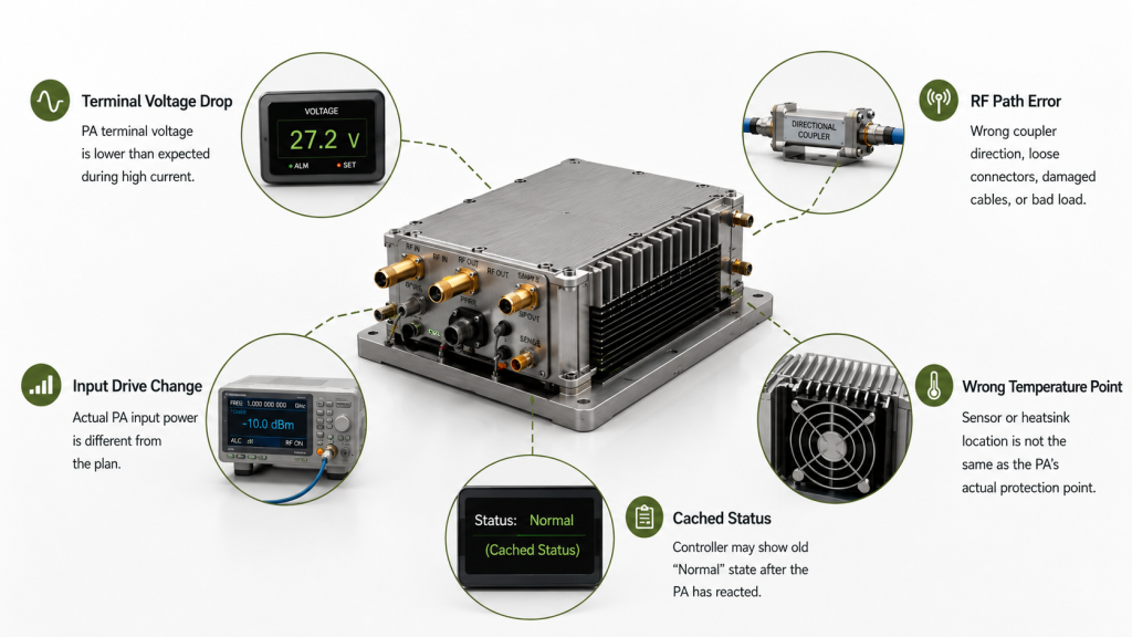
DC conditions can imitate protection faults
A PA may lose output because module-terminal voltage falls under load.
That behavior may be mistaken for:
- Over-current foldback
- Thermal derating
- Internal hardware failure
- Unstable protection logic
Record Vdc at the PA terminals and Idc during the event. Do not rely only on the power-supply display.
When output decline follows cable loss, shared-current loading, or startup voltage drop, separate RF PA output drops from DC power issues from the protection test.
Load and RF-path errors can imitate VSWR faults
A reflected-power event may come from:
- Incorrect dummy load
- Damaged RF cable
- Loose adapter
- Wrong connector
- Incorrect directional-coupler orientation
- Measurement reference-plane error
- Frequency-incompatible load
Confirm the complete RF path before judging the PA threshold.
Input drive can imitate foldback
If input drive changes during the test, Pout may fall without any protection action.
Record:
- Source output
- Source-path correction
- Actual PA input power
- PA output
- Gain
- Protection status
A power drop with no matching alarm or state change may not be foldback.
Temperature measurement can create a false conclusion
Different temperature points may show different values:
- Device junction estimate
- Internal sensor
- PA case
- Baseplate
- Heatsink
- Cabinet air
- Exhaust air
The acceptance plan should specify which temperature controls the protection test.
Do not compare an internal threshold with an external heatsink reading as if they were the same measurement.
Controller data can create a false pass
A controller may show:
- Cached Normal status
- Delayed Alarm
- Wrong module address
- Previous-channel data
- Automatic status clearing
- Missing timestamp
- Incorrect alarm polarity
- Floating alarm input
- Excessive debounce delay
A PA may have shut down correctly while the controller continues to display an old or incorrectly interpreted state.
Automatic recovery can hide a failure
A brief fault may trigger shutdown and then recover before the operator notices.
If only final output is checked, the test may appear to pass.
Record the complete event timeline, including:
- Trigger
- Output reduction
- Shutdown
- Alarm
- Recovery delay
- Reset or retry
- Final output
- Post-recovery stability
6. What Protection Evidence Belongs in RFQ and Acceptance
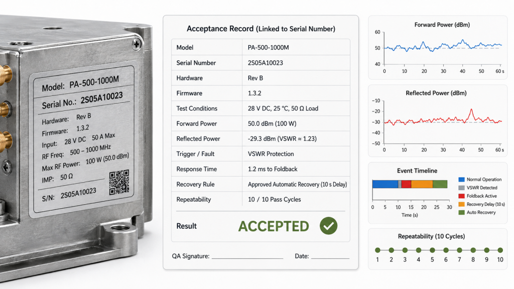
A useful RFQ should not state only:
Full protection required
That phrase does not define:
- Which faults are monitored
- Which thresholds apply
- What RF response is expected
- Which alarms are exposed
- Which events are latched
- How recovery should work
- What evidence the supplier must provide
RF PA Protection Acceptance Checklist
Module Identity
- Module model
- Serial number
- Hardware version
- Firmware version
- Interface version
- Report version
Test Conditions
- Frequency
- Input drive
- PA-port output
- Vdc and Idc
- RF load
- Forward power
- Reflected power
- VSWR
- Temperature
- Cooling condition
- Test duration
Protection Definition
- Fault type
- Trigger condition
- Approved test boundary
- Warning threshold
- Foldback threshold
- Shutdown threshold
- Latched-fault rule
- Alarm identity
- Alarm polarity
- Reset method
- Recovery delay
- Retry limit
- Abort conditions
Test Results
- Measured trigger value
- Trigger tolerance
- RF output before the event
- RF output during protection
- Response time
- Shutdown result
- Alarm timestamp
- Controller status
- Recovery delay
- Recovery result
- Post-recovery output
- Repeated-test spread
- Pass, Review, or Fail
Multi-Module Conditions
- Affected module identity
- Affected RF channel
- Unaffected-channel alarm state
- Shared-bus response
- Other-channel behavior
- Whether one-channel Reset clears another fault
- Group shutdown rule
- Recovery sequence
- Simultaneous-channel condition
The report should be linked to the tested serial number. A generic protection statement does not prove that the delivered unit behaves the same way as the sample.
What should the RFQ specify?
A stronger RFQ can include:
Required protection branches:
Warning behavior:
Foldback behavior:
Shutdown behavior:
Latched-fault behavior:
Alarm polarity and status format:
Reset method:
Automatic-recovery rule:
Recovery delay:
Retry limit:
Trigger tolerance:
Response-time tolerance:
Recovery-delay tolerance:
Required repeat count:
Allowed result spread:
Frequency and RF output condition:
Load or VSWR boundary:
DC test boundary:
Thermal test boundary:
Multi-channel response:
Required report format:
S/N-linked evidence requirement:
The final acceptance decision should be based on repeatable behavior under the same controlled conditions, not on the presence of a protection label in the datasheet.
FAQ
Does “full protection” prove that the logic is acceptable?
No. “Full protection” does not define trigger values, RF response, alarm identity, latch behavior, Reset rules, recovery delay, tolerance, or test evidence. These items must be documented and validated.
How can protection foldback be separated from weak PA output?
Confirm actual PA input power, module-terminal voltage, RF load, temperature, and protection status. Foldback should occur with a matching trigger and state change, and repeated tests should remain within the approved tolerance.
Should every protection fault recover automatically?
No. Mild or temporary conditions may allow delayed automatic recovery, while severe or repeated faults may require latched shutdown, fault clearance, and approved manual Reset.
Conclusion
RF PA protection acceptance should prove the complete path from a controlled fault trigger to RF response, controller visibility, approved recovery, and repeatable post-recovery output.
RF SKYPOWER can review RF PA protection behavior before sample approval or batch acceptance. Submit the module model and serial number, target frequency points, RF output, input drive, Vdc and Idc, load or VSWR boundary, temperature condition, fault-state map, alarm definitions, foldback or shutdown rule, Reset method, recovery delay, retry limit, trigger tolerance, required repeat count, and report format.
Contact RF Engineering Team to confirm that each protection state can be triggered, observed, recovered, and repeated within the same controlled acceptance boundary.