










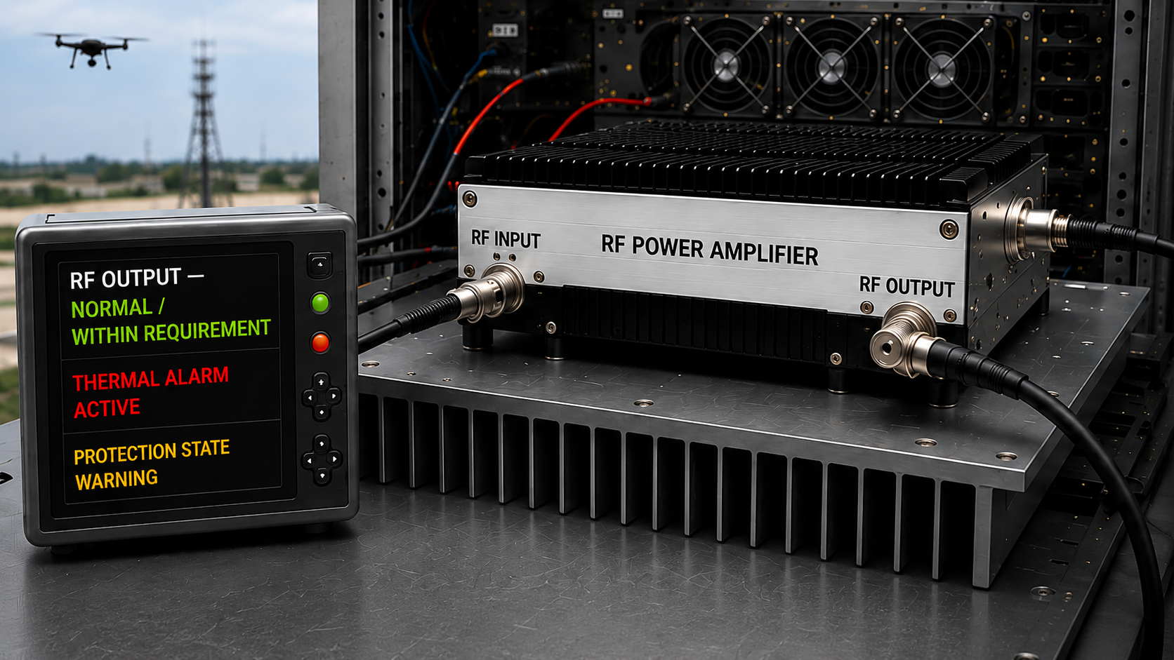
An RF PA thermal alarm can appear while measured RF output at the defined PA output reference plane still looks acceptable. That does not prove the amplifier is healthy, but the alarm alone also does not prove that the PA itself is overheating or defective.
For a custom RF Power Amplifier Module, the contradiction matters because the reported alarm, internal temperature sensing, external probe reading, RF operating point, cooling boundary, and protection threshold may not describe the same condition. Replacing the module immediately can therefore be just as premature as ignoring the alarm because Pout still looks normal.
So when RF output has not yet dropped, what evidence shows whether the event reflects a physically elevated thermal condition, a cooling-boundary problem, or a sensing and protection-state issue?
1. Why Normal RF Output Does Not Clear a Thermal Alarm
Normal RF output does not prove that the thermal condition is acceptable.
The PA may still produce the required Pout while the monitored thermal point is approaching or crossing a configured threshold.
Depending on the design, the monitored temperature may relate to:
- an internal device or board sensor;
- a module case location;
- a baseplate region;
- a heatsink or cooling interface;
- another internal thermal monitoring point.
The measured RF result and the thermal alarm therefore answer different questions.
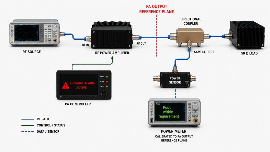
Pout at the defined PA output reference plane shows what RF output is being delivered at that measurement boundary.
A thermal alarm shows that the PA or controller reported a thermal-related protection state according to its configured sensing and threshold logic.
Those two facts can exist at the same time.
Depending on the configured protection logic, a thermal warning may occur before RF back-off or shutdown. Other implementations may transition differently, so the expected warning, foldback, shutdown, latch, or recovery behavior must be verified from the applicable protection definition.
Do not assume:
“Pout is still normal, so the thermal alarm must be false.”
Do not assume the opposite either:
“The thermal alarm appeared, so the PA has already physically overheated.”
The alarm state has to be tied to the correct temperature source, threshold, operating point, and protection response.
Where hot-state RF performance itself needs to be verified after stabilization, use a separate RF PA thermal soak review rather than treating one alarm event as a complete thermal-performance test.
2. What Does the RF PA Thermal Alarm Actually Represent?
A reported thermal alarm indicates that the PA or controller entered or reported a thermal-related protection state under its configured sensing and threshold logic.
The alarm alone does not prove the exact physical temperature at another measurement point, and it does not identify the root cause.
Before changing cooling hardware or replacing the PA, confirm:
- the alarm identity;
- the temperature source used by the protection logic;
- the applicable warning or shutdown threshold;
- whether the alarm is internal to the PA or generated by a higher-level controller;
- the expected RF response to that alarm;
- the expected reset or recovery behavior.
Do Not Treat External Probe Temperature as the Internal Protection Temperature
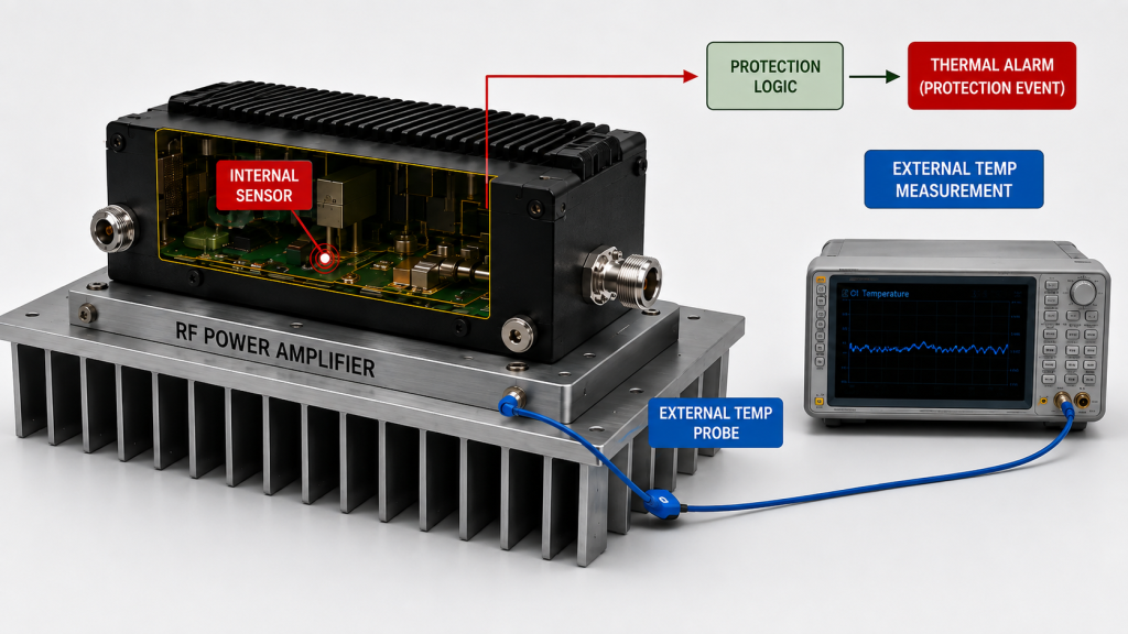
An external probe attached to the case, baseplate, heatsink, or nearby air measures temperature at that specific location.
It does not automatically reproduce the temperature seen by an internal protection sensor.
For that reason, a statement such as:
“The case was only warm, so the alarm cannot be real.”
is not sufficient evidence.
The correct comparison is:
Which sensor or temperature source actually drives the alarm, and what does the external measurement represent relative to that sensing point?
If external temperature measurements are being used for qualification or acceptance, the RF PA temperature-probe location should be defined separately, including the measurement point and attachment method.
Confirm the Alarm Before Changing the Threshold
If the reported thermal state does not match the expected protection behavior, first verify:
- status mapping;
- sensor source;
- threshold configuration;
- alarm timestamp;
- controller interpretation;
- hardware or firmware configuration where applicable.
Do not increase a thermal threshold simply because RF output still looks acceptable.
A changed threshold can hide the symptom without identifying whether the original event came from physical heating, sensing, configuration, cooling, or protection logic.
3. How to Correlate Pout, DC Input Power, Temperature, and Alarm Time
A useful thermal-alarm investigation should reconstruct the event in time.
Record, where applicable:
- frequency;
- Actual Pin or verified RF drive condition;
- Pout at the defined PA output reference plane;
- Vdc;
- Idc;
- calculated DC input power;
- relevant internal temperature reading;
- external temperature reading and location;
- duty cycle or CW condition;
- load condition;
- FWD / REV / VSWR where relevant;
- cooling condition;
- alarm timestamp;
- warning / foldback / shutdown / recovery state.
The purpose is to determine what changed before, during, and after the alarm.
Pout Alone Is Not Enough
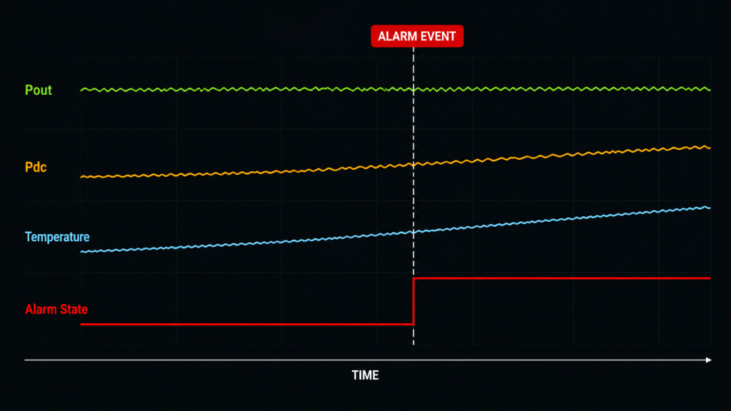
If Pout remains similar while the alarm appears, check whether the RF operating point is actually comparable.
For example:
- Actual Pin may have changed;
- supply voltage may have changed;
- DC current may have changed;
- the load condition may have changed;
- the duty cycle may have changed;
- the thermal state may have moved from cold to stabilized hot.
A similar Pout number does not prove the same electrical or thermal operating condition.
Interpret DC Input Power, Not Idc Alone
Do not interpret a change in Idc by itself as proof that DC input power or device dissipation increased.
Compare DC input power using:
Pdc = Vdc × Idc
If calculated Pdc increases while RF output remains similar under comparable frequency, Actual Pin, load, and thermal conditions, the additional DC input may indicate higher dissipation or another changed operating condition.
It still does not identify the root cause by itself.
Before assigning the event to efficiency or thermal behavior, also compare:
- frequency;
- Actual Pin;
- Pout;
- load condition;
- protection state;
- thermal state.
The useful evidence is the combination of RF output, DC input power, operating condition, and thermal response—not one current reading alone.
Keep Load and Thermal Effects Separate
A change in FWD / REV / VSWR can coincide with a thermal or protection event.
That does not automatically prove that mismatch caused the thermal alarm.
The useful question is:
Did the RF load condition change at the same time as the thermal event, and does the alarm remain when the load boundary is returned to a controlled condition?
Where the event points toward broader protection-state behavior, use the applicable RF PA protection-state validation rather than interpreting the thermal alarm in isolation.
| Observed Pattern | Next Controlled Check | What the Evidence Can Support |
|---|---|---|
| Thermal alarm is reported while Pout remains similar | Verify alarm identity, sensor source, threshold, and timestamp | A thermal-related state was reported; the physical root cause is not yet proven |
| Temperature rises under a comparable RF condition | Compare the defined temperature point, calculated Pdc, and cooling state | Thermal loading or the cooling boundary deserves further isolation |
| Calculated Pdc rises while Pout remains similar | Review Actual Pin, frequency, load, thermal state, and protection state | DC input power increased; higher dissipation or another operating change may be involved, but the root cause is not yet proven |
| Alarm appears only after cabinet installation | Compare controlled cooling with the installed cooling boundary | The installed thermal boundary becomes a stronger suspect |
| Alarm persists under controlled cooling and verified sensing | Recheck PA-side RF, DC, thermal, sensing, and protection conditions | The installed cooling boundary alone does not explain the event; PA-side electrical, thermal, sensing, protection, or hardware causes still require isolation |
4. When Should the Investigation Move to the Cooling Path?
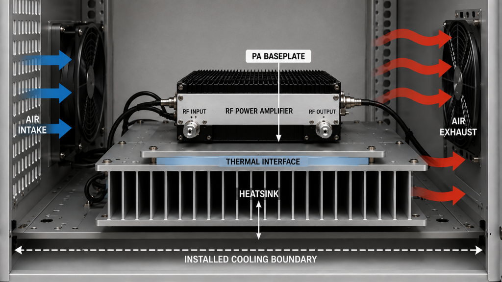
The cooling path becomes the next diagnostic boundary when the alarm changes with the installed thermal condition.
Examples include:
- the alarm disappears under controlled bench cooling but returns after cabinet installation;
- the event changes with fan or airflow condition;
- the event changes after the module-to-heatsink interface is reassembled;
- the event appears only after a longer thermal stabilization period;
- the alarm follows a repeatable change in the installed heatsink or airflow boundary.
The key is to change one thermal boundary at a time.
Do not simultaneously:
- replace the PA;
- change the alarm threshold;
- replace the fan;
- remount the heatsink;
- change the duty cycle.
If several variables are changed together, a later Pass result may not identify which change actually removed the alarm.
Check the Module-to-Heatsink Boundary
A module can have acceptable RF output while heat transfer from the module base into the heatsink is poor.
Relevant checks may include:
- contact surface condition;
- mounting flatness;
- clamping or fastening;
- thermal-interface material;
- uneven mechanical contact.
If the evidence points specifically toward the mechanical cooling interface, use an RF PA heatsink design check rather than expanding the thermal-alarm investigation into a complete heatsink-design review.
Check the Installed Airflow Boundary
A fan spinning does not by itself prove that the installed cooling path is adequate.
The final condition can still differ because of:
- airflow restriction;
- recirculation;
- cabinet closure;
- inlet or outlet obstruction;
- neighboring heat sources;
- ambient temperature.
The important comparison is whether the thermal alarm changes when the installed cooling boundary is reproduced under otherwise comparable RF and DC conditions.
Evidence shifts toward the cooling boundary when the alarm disappears under a controlled thermal condition but returns after the installed heatsink, airflow path, cabinet, or module-to-heatsink interface is restored under comparable operating conditions.
This still identifies a diagnostic boundary rather than a component-level root cause.
The next step is to isolate one part of that thermal path at a time.
5. What Evidence Should Be Saved Before the PA Is Replaced or Approved?
A thermal alarm should be investigated as a traceable event rather than a single screenshot.
Save, where applicable:
- delivered model and S/N;
- alarm timestamp;
- alarm identity;
- temperature source used by the protection logic;
- applicable threshold;
- external probe location, if used;
- frequency;
- Actual Pin or drive condition;
- Pout at the defined PA output reference plane;
- Vdc;
- Idc;
- calculated Pdc;
- duty cycle or CW condition;
- load or VSWR condition;
- cooling configuration;
- relevant temperature readings;
- warning / foldback / shutdown / recovery response;
- corrective action;
- final retest result.
Define the Hot-State Boundary
If the final decision depends on hot-state RF performance, do not use vague wording such as:
“after the PA got hot.”
Hot-state output means RF output measured after the defined thermal stabilization condition or test boundary has been reached.
The applicable stabilization rule may be based on a defined time, temperature behavior, project test procedure, or another approved criterion.
The exact boundary should be recorded with the final result.
Keep the Event Linked to the Delivered Unit
If the thermal alarm affects shipment, acceptance, or a field-return decision, the event record should remain linked to the delivered S/N.
The record should show:
- what condition triggered the event;
- what changed during troubleshooting;
- what was retested;
- under which thermal and RF boundary the final result passed.
A troubleshooting result from one unit should not be presented as proof that every unit in a batch has the same thermal behavior.
FAQ
Does an RF PA thermal alarm mean the amplifier is overheating?
Not automatically.
A thermal alarm means that a thermal-related state was reported under the configured sensing and threshold logic. The physical temperature, sensing point, threshold definition, controller status, and cooling condition still have to be verified before the root cause is assigned.
Why can RF output stay normal while a thermal alarm is active?
RF output and thermal protection monitor different conditions.
Depending on the configured protection logic, a warning can occur before RF back-off or shutdown. Pout may therefore remain acceptable at the defined PA output reference plane while the system is already reporting a thermal-related protection state.
What should be checked before replacing the RF PA?
Verify the alarm identity, sensing source, threshold, Actual Pin, Pout, Vdc, Idc, calculated Pdc, load condition, relevant temperature measurement, cooling boundary, and protection response.
If the alarm disappears only when the installed cooling condition changes, investigate the thermal boundary.
If the alarm remains under controlled cooling with verified sensing and configuration, the installed cooling boundary alone does not explain the event. Return the investigation to the PA-side electrical and thermal operating boundary, including Actual Pin, Pout, calculated Pdc, load condition, internal temperature behavior, sensing, protection logic, and hardware where applicable.
Conclusion
An RF PA thermal alarm at normal output should not be ignored simply because Pout still meets the RF requirement, and it should not be treated as automatic proof that the amplifier itself is defective.
First identify what thermal state the PA or controller actually reported, which sensor or temperature source drives that state, which threshold applies, and how the event correlates with Actual Pin, Pout, calculated Pdc, load condition, thermal behavior, and protection response.
If the alarm disappears under a controlled cooling condition and returns when the installed heatsink, airflow, cabinet, or module-to-heatsink boundary is restored under comparable RF, DC, load, and thermal conditions, the investigation should move into the installed cooling path.
If the alarm remains under controlled cooling with verified sensing, threshold configuration, and status mapping, the installed cooling boundary alone does not explain the event.
The investigation should then return to the PA-side electrical and thermal operating boundary, including:
- Actual Pin;
- Pout;
- calculated Pdc;
- load condition;
- internal temperature behavior;
- sensing;
- protection logic;
- hardware where applicable.
The alarm is therefore a diagnostic event that requires verification, not proof of the root cause.
For a custom RF Power Amplifier Module, define the target frequency and RF output condition, Actual Pin or drive rule, duty cycle, Vdc / Idc, load or VSWR boundary, cooling condition, temperature-sensing point, thermal alarm definition, protection response, recovery rule, and required S/N-linked test evidence before approval.
Contact us with the RF operating condition, thermal-alarm record, cooling boundary, load condition, and required acceptance evidence for your C-UAS RF PA project.