










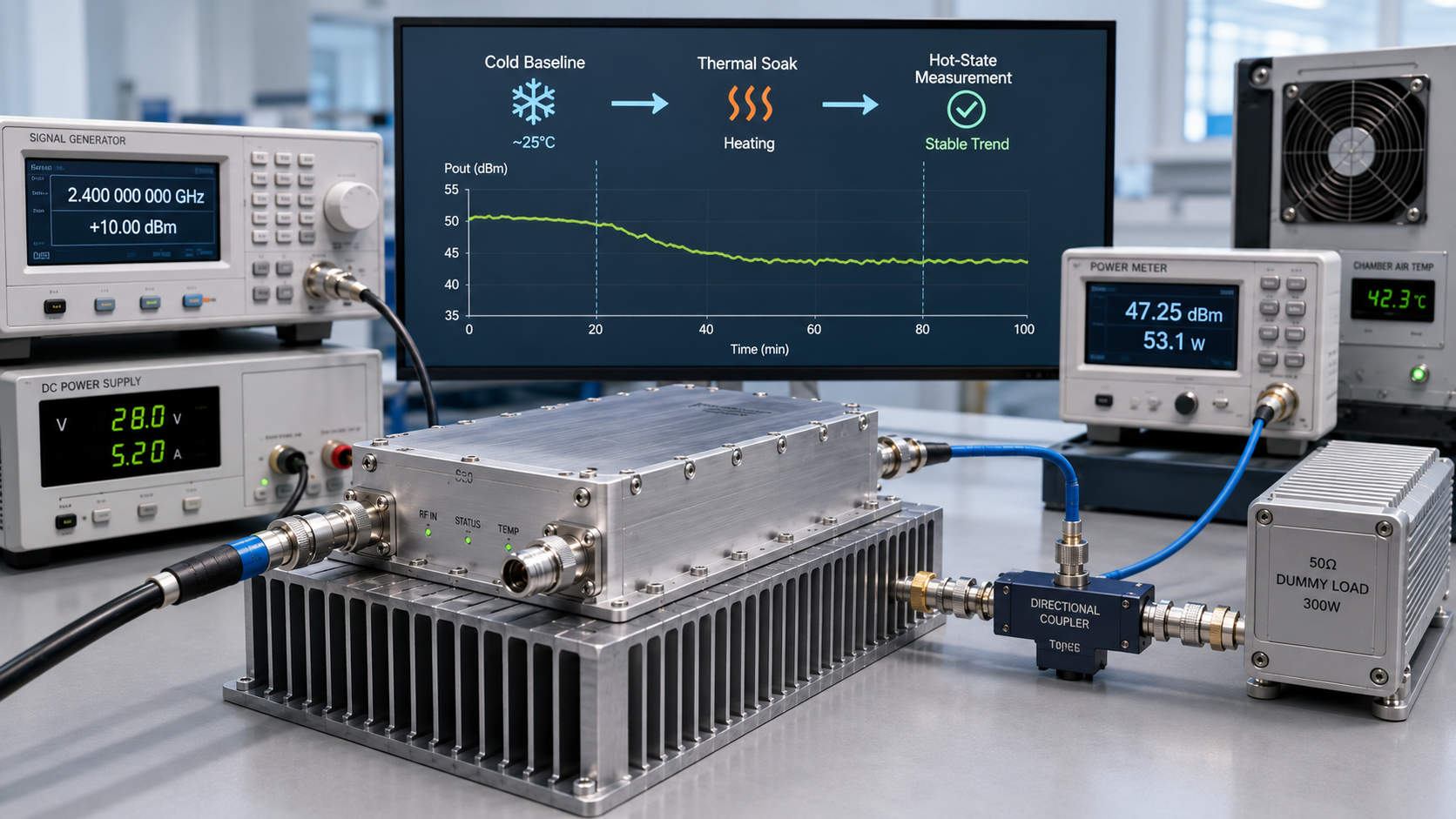
An RF PA can reach its target output during the first minutes of a bench test and still produce a different result once the module, heatsink, and surrounding thermal environment reach their real operating condition. That makes RF PA thermal soak more than a runtime checkbox.
The difficult part is deciding what a post-soak power reading actually proves. A lower hot-state Pout may come from the amplifier, but it can also come from input-drive drift, DC voltage drop, load or VSWR changes, cooling limits, protection back-off, or changes in the RF measurement chain.
For hot-state acceptance, a post-soak Pout result should be measured after the defined stabilization boundary at the specified reference plane and under the RF, DC, load, cooling, and measurement conditions required by the test procedure.
If the project also evaluates cold-to-hot thermal drift, an additional question must be answered: are the cold and hot measurements directly comparable?
1.What Thermal Soak Means in RF PA Power Testing
Thermal soak means operating the RF power amplifier under a defined load and thermal condition long enough for the relevant temperatures and electrical behavior to approach the operating state required by the test procedure.
The purpose is not simply to make the PA hot.
The purpose is to determine whether the required RF performance remains acceptable after the module, heatsink, DC path, and surrounding thermal environment have moved away from their initial cold condition.
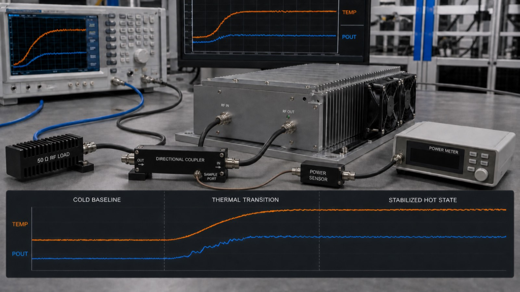
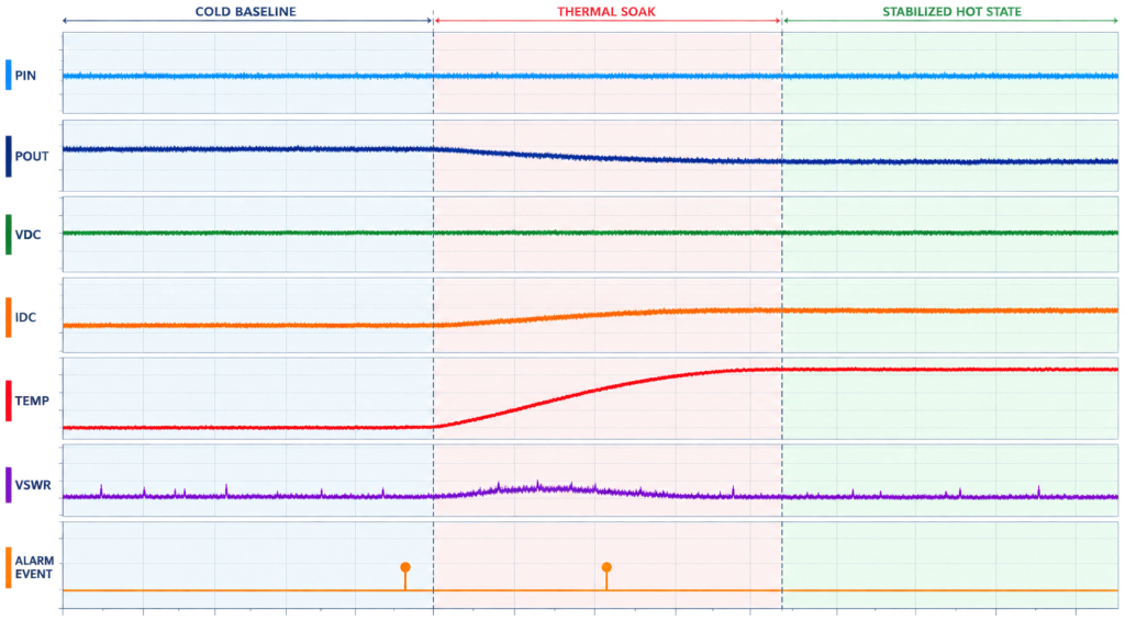
A useful thermal-soak test normally contains three measurement windows:
- Cold-state baseline — initial RF, DC, and temperature conditions are recorded before significant temperature rise.
- Thermal transition — Pout, Pin, temperature, current, and protection status are monitored while the system heats.
- Stabilized hot state — the final acceptance measurement is taken after the predefined stabilization boundary has been reached.
A fixed runtime can define the minimum soak duration, but it does not by itself demonstrate that the thermal state has stabilized.
Two systems operated for the same number of minutes can reach different thermal conditions because of differences in duty cycle, heatsink size, fan performance, cabinet restriction, ambient temperature, DC behavior, and RF load.
The practical acceptance question is therefore:
Has the PA reached the hot operating condition defined by the test procedure, and is the final Pout measured under the required test boundary?
2.Why Cold RF PA Power Can Mislead Acceptance
A cold-state measurement is useful. It confirms that the RF path, input drive, DC supply, load, and measurement setup can produce the expected result at the start of the test.
But a cold reading should not automatically be treated as proof of hot-state performance.
As temperature changes, several electrical behaviors may also change:
- gain;
- output power;
- DC current;
- efficiency;
- compression behavior;
- protection margin;
- device and matching-network behavior.
This does not mean every RF PA must show a significant thermal shift. A well-designed amplifier may remain relatively stable.
The risk is assuming stability without measuring the required hot operating condition.
If hot-state Pout is lower than the cold-state result, the difference should first be treated as an observed change in the test result—not as proof that the PA itself has degraded.
Possible causes include:
- lower Pin at the PA input;
- DC voltage drop;
- load or VSWR change;
- protection back-off;
- inadequate cooling;
- a changed RF measurement-chain correction;
- temperature-dependent behavior inside the amplifier.
If gain stability is the main acceptance question, it should be verified separately using a dedicated RF PA hot-state gain procedure.
For this thermal-soak test, the primary question is whether the final post-soak Pout is trustworthy under the defined acceptance boundary.
3.What Must Stay Controlled Before Comparing Cold and Hot Pout
Hot-state acceptance and cold-to-hot thermal drift are related, but they are not identical checks.
If the requirement is simply a stabilized hot-state Pout, the result should be judged against the specified hot-state reference plane and operating conditions.
If thermal drift is also being calculated, the cold and hot measurements must remain directly comparable.
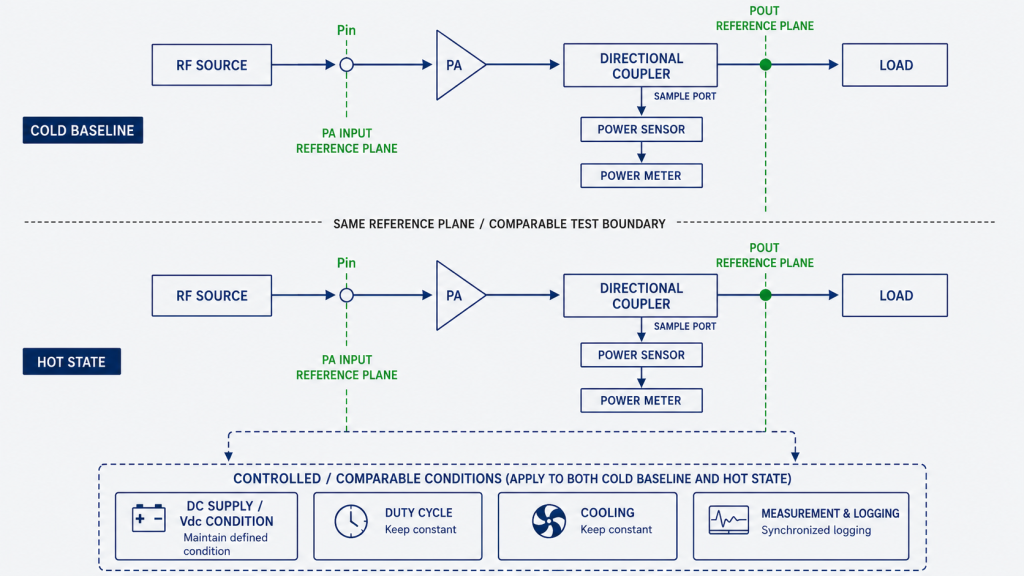
Cold-state and post-soak Pout should therefore use the same defined measurement reference plane when they are compared with each other.
A displayed power value may include the effects of cables, connectors, attenuators, directional couplers, adapters, fixtures, or other losses between the PA output and the instrument.
If the required Pout is defined at the PA output port, the measurement and correction chain must allow the reported value to be traced back to that reference plane.
| Test boundary | What should be defined | Why it matters |
|---|---|---|
| Frequency | Exact test frequency or frequency points | Pout and gain may vary across the operating band |
| Input drive | Pin at the defined PA-input reference plane, or a calibrated drive condition related to that plane | Lower input drive can look like thermal output loss |
| Output reference plane | PA output port, coupler reference plane, or another explicitly defined plane | Prevents comparison of different power definitions |
| RF correction | Applicable cable, connector, attenuator, coupler, and fixture correction | Separates measurement-path effects from PA behavior |
| Load condition | Defined load or VSWR boundary | Load changes can alter output and protection behavior |
| DC supply | Vdc at the defined point and relevant current-limit condition | Supply drop can reduce available RF output |
| Duty cycle | CW or defined pulse / on-off profile | Thermal loading depends strongly on duty cycle |
| Cooling | Heatsink, airflow, fan state, cabinet condition, and interface assumption | Cooling determines the hot operating state |
| Ambient condition | Relevant room, inlet-air, or cabinet ambient condition | Improves repeatability between tests |
| Stabilization rule | Predefined thermal and/or electrical stability criterion | Prevents choosing the endpoint after seeing the result |
| Acceptance limit | Required hot-state Pout, allowed drift if applicable, and protection behavior | Converts measurements into an acceptance decision |
If acceptance is based on corrected Pout, record:
- the raw instrument reading;
- the applicable correction factor or loss value;
- the defined output reference plane;
- the final corrected Pout.
This allows the result to be independently traced.
For cold-to-hot comparison, the reference plane should remain the same. The numerical correction value itself should only be reused if it remains valid for the actual RF measurement-chain condition.
A cable, directional coupler, attenuator, connector, adapter, or sensor can change with temperature. A correction value that was valid under one condition should not be assumed automatically to remain valid under another if the measurement chain itself has changed.
Thermal soak should therefore be treated as one controlled operating condition within a broader full-power RF PA test, not as a substitute for defining frequency points, drive, load, DC conditions, and measurement reference planes.
4.How to Define the Thermal Stabilization Boundary
“Run the PA for 30 minutes” or “test until it is hot” is not specific enough when the acceptance decision depends on the stabilized thermal state.
Time can still be part of the requirement.
A stronger procedure combines minimum runtime with observable thermal or electrical stability.
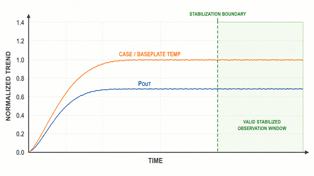
Depending on the project, useful stabilization evidence may include:
- PA case or baseplate temperature trend;
- heatsink temperature trend;
- cabinet or local inlet-air temperature;
- Pout trend;
- Pin trend;
- Vdc and Idc;
- protection or alarm status.
The stabilization criterion should be defined before the test starts.
For example, the procedure may require the relevant temperature trend and output-power trend to remain within project-defined limits for a specified observation window.
The exact limit should come from the product requirement, customer specification, or agreed acceptance procedure. It should not be invented after the measurement result is already known.
A stable case or heatsink temperature is an observable test criterion. It should not be described as a direct semiconductor junction-temperature measurement unless the test method actually measures or derives junction temperature.
Thermal behavior is also not always monotonic.
A PA may appear stable early in the test and then change again as the heatsink, cabinet air, DC path, or surrounding equipment continues to warm.
For that reason, time-correlated trend data is normally more useful than one isolated temperature value.
Why Long-Duty Fixed Sites Raise the Acceptance Requirement
Thermal-soak evidence becomes more important when the actual application operates for long duty periods or inside a restricted enclosure.
A bench result with unrestricted airflow may not represent the thermal condition reached after installation.
Fan working point, filter restriction, recirculated exhaust air, neighboring heat sources, cabinet layout, and inlet-air temperature can all change the final operating state.
The thermal-soak result should therefore be interpreted within the environment that was actually tested.
It does not automatically prove performance in every possible cabinet or deployment condition.
When cabinet airflow itself is uncertain, it should be verified separately rather than turning thermal-soak acceptance into a complete enclosure-design procedure. See the dedicated RF PA cabinet airflow checks under full load for that boundary.
5.What Evidence Should Be Recorded Before, During, and After Thermal Soak?
A useful thermal-soak report should make it possible to reconstruct what happened during the test.
One final hot-state wattage value is usually insufficient for diagnosing a disputed result.
The report should preserve the initial condition, the transition into the hot state, and the final stabilized measurement.
| Evidence | Cold baseline | During thermal soak | Stabilized hot state |
|---|---|---|---|
| Frequency | Record | Confirm unchanged | Record |
| Pin | Record at defined input reference plane | Trend or periodic checks | Record |
| Raw Pout reading | Record | Trend or periodic checks | Record |
| Pout reference plane | Define | Keep unchanged if comparing drift | Confirm |
| RF correction | Record correction factor or loss value | Keep the chain defined and note conditions that may change the correction | Record the correction applied to the final result |
| Corrected Pout | Record if required | Calculate only when relevant | Record final value |
| Vdc | Record | Trend or periodic checks | Record |
| Idc | Record | Trend | Record |
| PA / heatsink temperature | Record starting value | Trend | Record stabilized value |
| Cabinet / local ambient | Record if relevant | Trend | Record |
| Load / VSWR condition | Record | Monitor | Confirm |
| Protection / alarm status | Record | Log events and timestamps | Record final state |
| Duty cycle | Define | Maintain | Confirm |
| Cooling condition | Define | Maintain and record changes | Confirm |
| Unit identification | Record S/N | Maintain traceability | Include in final result |
The most useful report links these measurements by time.
A temperature increase without simultaneous Pin, Pout, Vdc, and Idc information leaves uncertainty about what changed.
Likewise, one screenshot of final Pout does not show what happened during the transition.
Where practical, also record:
- test-equipment identification;
- relevant calibration status;
- fixture and correction information;
- software or controller logs;
- alarm timestamps;
- test-start and test-end times;
- operator notes for any manual change.
Manual intervention should be traceable.
If the operator changes input drive, fan speed, supply voltage, load condition, attenuation, or an instrument setting during the run, record when and why the change occurred.
Otherwise, the final hot-state result may appear comparable with the cold baseline even though the test boundary changed.
For shipment or batch acceptance, thermal-soak evidence can also become one part of broader RF PA reliability test evidence before shipment rather than being treated as proof of every reliability requirement.
6.How to Diagnose a Pout Drop After Thermal Soak
A lower post-soak Pout should trigger diagnosis, not an immediate conclusion that the RF PA is defective.
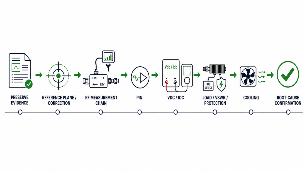
The correct sequence is to preserve the observed condition and determine which part of the test boundary changed.
| Observation or check | What to verify | What not to conclude too early |
|---|---|---|
| Pout is lower | Output reference plane and RF correction | Do not assume the PA itself lost the same amount of power |
| Pin changed | Drive source, cable loss, attenuator, coupler, PA-input reference plane | Do not call it PA gain compression before confirming drive |
| Vdc changed | Supply output, wiring drop, connector drop, current limit | Do not classify the result as purely thermal |
| Idc changed | Compare with Pin, Pout, Vdc, and protection state | Current change alone does not identify the root cause |
| Load / REV changed | Dummy load, RF path, connector condition, VSWR | Do not ignore mismatch-related output reduction or protection |
| Temperature continues rising | Cooling, interface, airflow, cabinet condition | Do not declare the system thermally stabilized |
| Alarm or protection occurred | Protection log and timestamp | Do not treat reduced Pout as unexplained analog drift |
| Reading recovers after cooling | PA and RF measurement chain | Recovery shows a temperature-dependent effect, not automatically a PA fault |
Start with the measurement definition.
Confirm that the compared readings use the intended Pout reference plane and valid RF correction.
Then verify the RF measurement chain before assigning the change to the amplifier.
A directional coupler, attenuator, RF cable, connector, adapter, or power sensor can create an apparent Pout shift if its behavior changes with temperature.
Next, confirm Pin at the defined PA-input reference plane.
A signal-generator setting is not automatically the same as the actual Pin delivered to the amplifier.
If Pin drops, Pout may drop even when the PA itself remains healthy.
Then verify the DC path.
The power supply may still display its nominal voltage while the voltage available at the PA is lower because of cable, connector, or distribution losses.
For a high-power module, Vdc and Idc should therefore be interpreted together with the RF result.
Check the RF load condition as well.
A changing VSWR or load can alter delivered output and may also trigger protection or output back-off.
Where the setup provides the information, FWD, REV, VSWR, and alarm data can help distinguish a load-related event from an internal PA change.
Cooling is another possible cause, but “thermal problem” is still too broad a diagnosis.
Check:
- heatsink contact;
- thermal-interface condition;
- fan operation;
- airflow direction;
- blocked filters;
- recirculation;
- cabinet restriction;
- nearby heat sources.
If the installation interface itself is suspect, use the dedicated guidance on RF PA thermal grease and contact mistakes instead of changing the interface blindly during the acceptance run.
Most importantly, preserve the original evidence before changing the suspected cause.
If a hot-state Pout drop occurs, first record the measurement condition, Pin, raw and corrected Pout where applicable, Vdc, Idc, temperatures, load or VSWR information, and protection status.
Then change one relevant condition at a time.
A lower hot-state Pout is evidence that the measured result changed under the observed condition; it is not, by itself, evidence that the RF PA is defective.
If the reading recovers after the PA and RF measurement chain cool, the result confirms a temperature-dependent effect somewhere in the tested system. It does not by itself identify the RF PA as the root cause.
7.What Thermal-Soak RFQs Should Define
Thermal-soak acceptance is much easier when the requirement is defined before testing begins.
“Full power after warm-up” is not specific enough for repeatable acceptance unless the reference plane, operating conditions, stabilization boundary, and required result are also defined.
| RFQ item | What should be defined |
|---|---|
| Operating frequency | Exact frequency range and required test points |
| Target output power | Required hot-state Pout and reference plane |
| Input condition | Pin at the defined input reference plane, drive range, or calibrated source condition |
| RF measurement | Reference plane, measurement method, applicable correction factors, and required traceability |
| Load condition | Nominal load and required VSWR boundary |
| DC supply | Nominal Vdc, acceptable variation, and current-limit condition |
| Duty cycle | CW or defined pulse / on-off profile |
| Cooling | Heatsink, airflow, fan condition, cabinet boundary, and interface assumption |
| Ambient condition | Required ambient or cabinet inlet condition when relevant |
| Thermal stabilization | How the required hot state is defined |
| Hot-state acceptance | Minimum or allowable Pout result at the defined reference plane |
| Thermal drift | Allowed cold-to-hot variation, if drift is part of acceptance |
| Protection behavior | Which alarms, trips, or back-off conditions are acceptable |
| Evidence format | Trend data, screenshots, logs, timestamps, or formal report |
| Traceability | Unit S/N and test-equipment identification |
The RFQ should also distinguish module-level acceptance from installed-system acceptance.
A PA can be tested using a defined heatsink, RF load, DC supply, airflow condition, and ambient boundary.
That result describes the tested condition. It does not automatically guarantee the same thermal state inside a different customer cabinet.
If the required evidence must represent the installed system, the relevant cabinet, airflow, duty cycle, load, ambient, and measurement assumptions should also be included in the acceptance boundary.
For RFQs that require hot-state acceptance evidence, define these conditions before selecting the RF PA module.
FAQ
Is thermal soak the same as burn-in?
No.
Thermal soak is used to reach and evaluate a defined hot operating state so electrical performance can be measured under that condition.
Burn-in typically refers to a longer reliability-screening process intended to expose early failures or unstable behavior over extended operation.
A test program may include both, but one does not automatically replace the other.
How long should an RF PA thermal-soak test run?
There is no single valid duration for every PA and installation.
The procedure may specify a minimum soak time, but when thermal stabilization itself matters, the final measurement should also satisfy the predefined thermal or electrical stabilization criterion.
What should be measured after thermal soak?
At minimum, the final Pout result should be interpreted with the test frequency, Pin at the defined input reference plane, Pout reference plane, applicable RF correction, Vdc, Idc, temperature, load condition, duty cycle, cooling state, and protection status.
If cold-to-hot thermal drift is part of the acceptance requirement, the cold-state baseline should use a directly comparable test boundary.
Conclusion
RF PA power after thermal soak can support hot-state acceptance when it is measured at the specified reference plane after the defined hot operating condition has been reached, with RF drive, DC supply, load, duty cycle, cooling, measurement correction, and protection criteria controlled as required by the test procedure.
If the acceptance decision also depends on cold-to-hot power drift, the cold and hot measurements must use the same reference plane and directly comparable test conditions. Otherwise, the difference between the two readings cannot be assigned confidently to thermal behavior of the PA.
A lower hot-state Pout does not by itself prove an RF PA fault. Pin, the DC path, load or VSWR, protection state, cooling condition, and the RF measurement chain should be checked before assigning the cause to the amplifier.
For hot-state acceptance, the strongest evidence is a traceable Pout measurement taken after the defined stabilization boundary under controlled and documented test conditions. When thermal drift is also part of the acceptance requirement, add a directly comparable cold-state baseline.
For an RF PA project that requires hot-state acceptance evidence, include the operating band, target Pout, Pin or drive-source condition, measurement reference plane, Vdc / Idc limits, duty cycle, cooling method, ambient condition, load or VSWR boundary, stabilization rule, allowed output drift if applicable, and required S/N-linked test report in the RFQ.
Defining these conditions before module selection helps prevent a cold bench result, a stabilized hot-state result, and an installed-system result from being treated as if they were measured under the same acceptance boundary.
Contact us with your RF PA frequency range, target output power, duty cycle, cooling condition, measurement reference plane, and acceptance requirements so these test conditions can be defined clearly before the RFQ is finalized.