










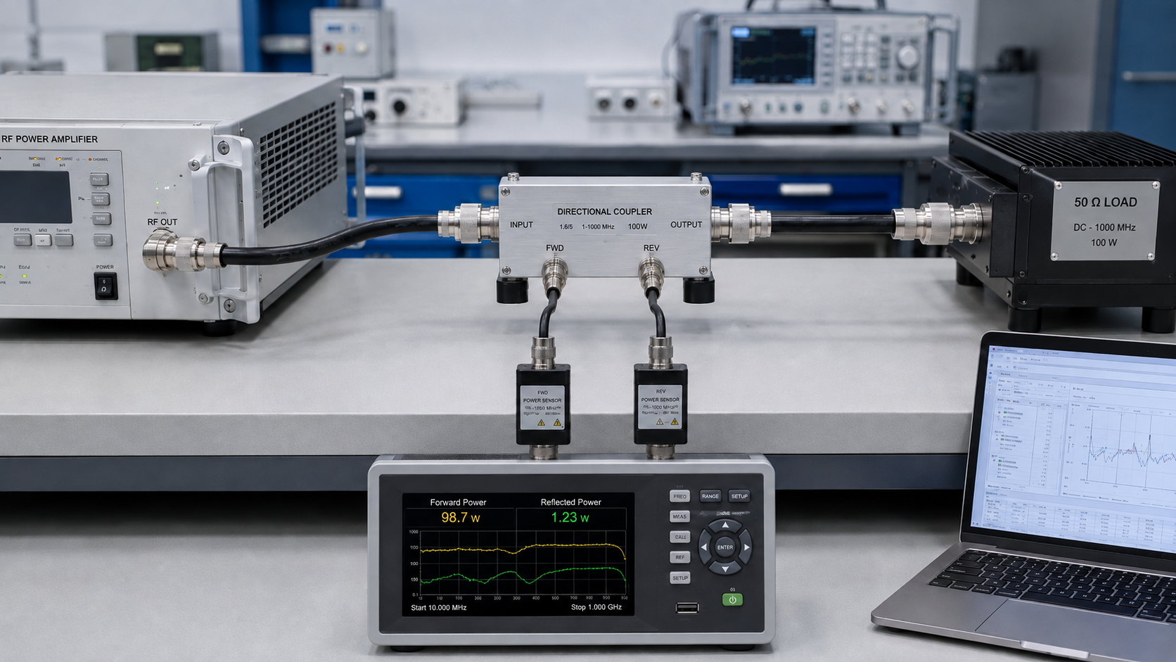
A strong forward-power screenshot can make an RF PA test look complete while leaving one critical question unanswered: what was the load doing at that same moment? Reflected power logging only becomes useful when the reverse reading can be tied to the same RF event instead of a separate screenshot or a later note.
Even two valid FWD and REV numbers may be misleading if they come from different frequencies, different measurement planes, different drive conditions, or different operating states. A useful log needs enough context to show what the directional readings actually represent.
So what must be recorded before an RF PA FWD/REV log can be trusted as acceptance evidence?
1.Why Forward Power Alone Is Not Enough for RF PA Acceptance
Forward power shows how much RF power is traveling toward the load at the stated measurement plane.
That is important, but it does not describe the complete load condition.
An RF PA may show the expected FWD while part of the transmitted energy is being reflected back toward the source. Depending on the RF path and protection architecture, that reflected condition may affect delivered power, protection behavior, thermal stress, or whether the installed system remains inside the intended operating boundary.
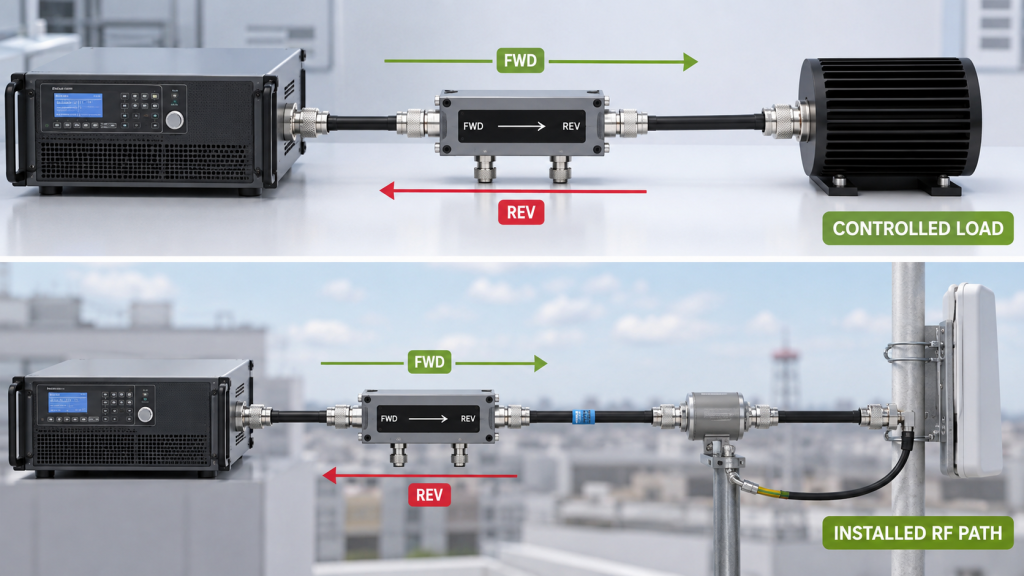
This becomes especially important when the test moves from a controlled bench load to an installed RF path.
A bench test may use a known load and short RF path. The installed system may add:
- longer feeders;
- connectors and adapters;
- filters or combiners;
- switches;
- antenna matching effects;
- installation-dependent bends or routing;
- frequency-dependent loss and mismatch.
The purpose of logging REV is therefore not to prove that the PA is healthy or faulty from one number.
It is to preserve evidence of the reflected-power condition that existed when the corresponding forward-power result was recorded.
Where a controlled load and an installed antenna chain need to be distinguished, treat them as different test boundaries rather than assuming that one result represents the other. A dedicated dummy-load versus real antenna chain check can be used for that distinction.
2.What FWD, REV, and VSWR Can—and Cannot—Prove
FWD, REV, VSWR, and return loss are related to RF reflection, but they are not interchangeable acceptance values.
FWD and REV are directional power measurements.
They describe power traveling in opposite directions at a stated directional measurement location or corrected reference plane.
VSWR or return loss describes a mismatch condition at a defined plane and measurement method.
Depending on the test setup, VSWR or return loss may be measured directly or derived from directional measurements.
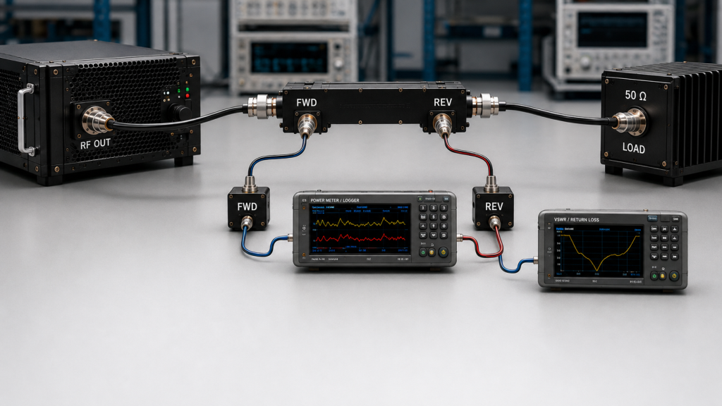
That distinction matters.
A report that lists:
- FWD;
- REV;
- VSWR;
- return loss;
without stating where and how those values were obtained may appear complete while still leaving the acceptance boundary unclear.
When FWD and REV are compared or used to derive a reflection metric, both directional readings should refer to the same defined reference plane.
The log should identify the directional measurement location, the applicable correction for each directional reading, and the frequency associated with that correction.
What a higher REV reading proves
An increase in REV is an observation of a changed reflected-power condition at the stated measurement plane.
But a higher absolute REV value does not necessarily mean that the mismatch became worse.
If FWD also increased, REV can rise even when the underlying reflection condition remains similar. REV should therefore be interpreted together with the corresponding FWD at the same defined reference plane.
When mismatch severity is being compared, use the reflection metric defined by the acceptance procedure—such as VSWR, return loss, or another valid FWD/REV-based quantity—rather than comparing REV watts alone.
f the reflection problem appears only at particular operating frequencies, treat it as a frequency-specific VSWR question rather than assigning the change from one isolated FWD/REV event.
An increase in REV may still justify further investigation of:
- load mismatch;
- antenna-path changes;
- connector or feeder conditions;
- frequency-dependent behavior;
- protection activation;
- installation changes.
But REV alone does not prove that the PA is defective.
It also does not automatically identify one particular downstream component as the root cause.
Root-cause isolation requires additional evidence.
For example, comparison with a controlled load may help determine whether the changed condition follows the PA or the installed RF path. Protection logs, section-by-section isolation, or other RF measurements may then narrow the fault boundary further.
If the main problem is a field mismatch or protection event, use the dedicated guidance on RF PA VSWR field failures rather than assigning the fault from one REV value.
What a low REV reading proves
Low REV can support a lower reflected-power condition at the stated directional measurement plane.
But a very low reverse reading is only useful quantitatively when it remains sufficiently above the effective reverse-channel measurement floor.
That limit can depend on:
- directional-coupler directivity;
- coupling factor;
- frequency response;
- cable and connector loss;
- sensor sensitivity;
- sensor dynamic range;
- residual leakage between directional channels;
- applicable correction.
A low displayed REV should therefore not be expanded into a broader claim that every downstream component is correctly installed or matched.
The strongest statement the log can support is the reflected-power condition observed at the declared measurement plane under the recorded test conditions and within the usable range of the measurement chain.
3.How to Log Time-Correlated FWD and REV at the Same Reference Plane
A useful FWD/REV record should make it possible to reconstruct one operating event.
That means the directional readings need more context than two power values placed in the same report.
FWD, REV, and protection status should be time-correlated to the same operating event, with frequency, drive condition, load state, thermal state, and measurement reference plane identified in the record.
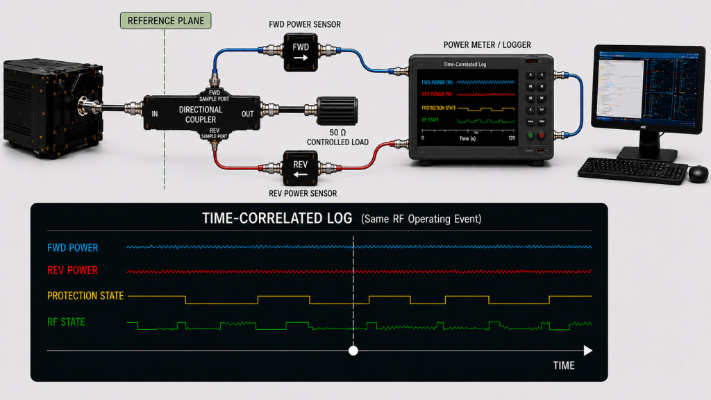
Time-correlated does not require every instrument to sample at exactly the same microsecond.
The practical requirement is that the data can be shown to represent the same relevant RF operating condition.
For example, the log should make clear whether:
- FWD was measured before or after a protection event;
- REV was captured before or after the load changed;
- the PA was cold, warming, or thermally stabilized;
- drive level changed between readings;
- the measurement correction changed;
- frequency changed between events.
Without that context, two individually valid readings may still be unsuitable for direct comparison.
Define the directional reference plane
The acceptance procedure should state where FWD and REV are represented.
Possible locations may include:
- a directional-coupler plane;
- a PA output reference plane;
- another explicitly defined point in the RF path.
The important requirement is consistency.
If a directional reading is de-embedded from the coupler plane to another reference plane, the correction must account for the propagation direction and insertion loss between the two planes.
Do not assume that one undifferentiated cable-loss correction can be applied to FWD and REV in the same way.
For example, the forward wave travels from the PA toward the load, while the reflected wave travels back toward the PA. The correction used to represent both quantities at another plane must preserve that directional relationship.
Where relevant, record:
- raw FWD reading;
- raw REV reading;
- coupler factor or directional calibration data;
- cable, connector, or fixture loss used in the correction;
- frequency associated with each correction;
- corrected FWD;
- corrected REV;
- stated reference plane.
Do not assume that one correction value remains valid across the complete operating band unless the measurement method supports that assumption.
Any derived VSWR or return-loss value is only as valid as the FWD/REV measurements, directional corrections, and reference-plane definition used to calculate it.
Keep the operating condition attached to the reading
At minimum, the FWD/REV event should be traceable to:
- test frequency;
- Pin or defined drive condition;
- FWD;
- REV;
- directional measurement plane;
- applicable correction;
- load condition;
- Vdc;
- Idc where relevant;
- thermal state;
- protection or alarm status;
- timestamp;
- unit S/N.
If the test uses more than one load state, such as a controlled dummy load and an installed antenna path, identify the load state explicitly rather than placing the results in one undifferentiated table.
4.What Should an RF PA FWD/REV Acceptance Record Include?
An acceptance record should show not only what was measured, but also what the evidence can support.
When directional evidence is required during powered acceptance, the FWD/REV record should sit inside the broader full-power RF PA test boundary rather than being treated as a stand-alone proof of overall PA performance.
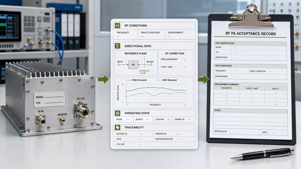
| Evidence item | What to record | Required condition or reference | What it supports | What it does not prove |
|---|---|---|---|---|
| Frequency | Exact test frequency or point | Same frequency for directly compared data | Frequency-specific evidence | Performance across untested frequencies |
| Drive condition | Pin or calibrated drive state | Defined input reference or source condition | Whether the PA was driven under the intended condition | PA behavior under a different drive level |
| FWD | Raw and/or corrected directional value | Declared directional reference plane | Forward-power condition at that plane | Antenna-end delivered power unless that plane is explicitly defined |
| REV | Raw and/or corrected directional value | Same declared reference basis used for interpretation | Reflected-power condition at that plane when interpreted with the corresponding FWD | Root cause or mismatch severity from REV watts alone |
| RF correction | Directional coupler data, cable loss, fixture correction, or other applicable value | Valid for the frequency, propagation direction, and measurement condition | Traceability from raw reading to reported value | Correctness of an undocumented or invalid de-embedding method |
| Reflection metric | VSWR, return loss, or another defined quantity when required | Derived or measured at a stated reference plane using a valid method | Mismatch severity under the stated condition | Root cause of the mismatch |
| Load condition | Dummy load, installed path, or stated VSWR boundary | Identified for each event | Which RF path was being tested | Behavior under another load |
| Thermal state | Cold, warming, stabilized hot, or another defined state | Defined by the test procedure | Operating state associated with FWD/REV | Performance under a different thermal condition |
| Protection state | Normal, warning, back-off, foldback, shutdown, or other logged state | Time-correlated with the RF event | Whether protection influenced the observed result | Root cause without additional diagnosis |
| Timestamp | Test time or event time | Same event sequence | Correlation between FWD, REV, protection, and operating state | Measurement validity by itself |
| Unit identity | Module S/N | One unit linked to its test record | Unit-level traceability | Batch-wide performance unless the sampling plan supports it |
A record structured this way is more useful than a single screenshot because it preserves the conditions needed to interpret the directional readings later.
Preserve observation before diagnosis
If REV rises during a test, first preserve:
- FWD;
- REV;
- frequency;
- drive state;
- load state;
- measurement plane;
- applicable directional correction;
- protection status;
- relevant DC information;
- timestamp.
Then investigate the cause.
This order matters because changing a cable, antenna, connector, load, drive level, or protection setting before recording the original condition can destroy the evidence needed to compare the before-and-after states.
Use unit-linked evidence when unit-level acceptance is required
Where acceptance is performed per delivered module, the report should keep the directional data linked to the unit identity.
A useful traceability structure is:
One Unit → One S/N → One Time-Correlated Dataset → One Report
This is an acceptance-evidence structure, not a statement that every project requires the same reporting format.
The actual requirement should be defined by the customer specification, acceptance procedure, or RFQ.
5.What Should the RFQ Define for FWD/REV Acceptance?
“Provide forward and reflected power data” is too vague for repeatable acceptance.
The RFQ or acceptance procedure should define what the buyer expects the directional measurements to represent.
| RFQ item | What should be defined |
|---|---|
| Operating frequency | Required frequencies or test points |
| Target RF output | Required output and stated reference plane |
| Drive condition | Pin or calibrated source condition |
| Directional measurement plane | Where FWD and REV are represented |
| Measurement method | Coupler, sensor, or other directional measurement method |
| RF correction | Direction-aware correction or de-embedding basis and required traceability |
| Load condition | Dummy load, installed path, or defined VSWR boundary |
| FWD requirement | Required forward-power evidence or tolerance |
| REV requirement | Required absolute REV limit or FWD-normalized reflection requirement, with the applicable operating condition defined |
| Reflection metric | Whether VSWR, return loss, FWD/REV, or another requirement governs acceptance |
| Thermal condition | Cold, hot, or another specified operating state |
| Protection behavior | Acceptable warning, back-off, foldback, or trip behavior |
| Logging timing | Required sampling interval, event timing, or capture method |
| Unit traceability | Whether results must be linked to individual S/N |
| Report format | Required tables, plots, logs, screenshots, or formal report |
The RFQ should avoid treating different reflection metrics as if they were interchangeable.
If acceptance is specified by VSWR or return loss, define that requirement directly.
If FWD and REV are required as directional evidence, state:
- where they are represented;
- how each directional reading is corrected;
- when they are recorded;
- whether the limit is absolute or normalized to the corresponding FWD;
- which operating state applies.
When FWD/REV evidence is part of module approval, define these boundaries before selecting the RF PA module.
FAQ
Is Forward Power enough for RF PA approval?
Not when the acceptance requirement also depends on reflected-power behavior, load condition, or mismatch protection.
FWD can confirm the forward-power condition at the stated reference plane, but it does not by itself show the reflected-power condition that existed during the same operating event.
If REV or another reflection metric is part of acceptance, record it together with the corresponding FWD and the required measurement context.
Does high REV prove that the RF PA or antenna path is faulty?
No.
High REV shows an increased reflected-power value at the stated directional measurement plane.
Its significance depends on the corresponding FWD and the reflection metric defined by the acceptance procedure.
A higher REV wattage alone does not prove a worse mismatch, and it does not identify the root cause.
Preserve the original event first, then use controlled-load comparison and other diagnostic evidence to isolate the problem.
Is VSWR the same as reflected power?
No.
FWD and REV are directional power measurements.
VSWR is a mismatch metric associated with a defined measurement plane and method. It may be related to FWD and REV, but the values are not interchangeable.
For acceptance, the report should state which metric is required, where it applies, and how it is measured or derived.
Conclusion
FWD and REV become useful RF PA acceptance evidence when they are tied to the same operating event, represented at a clearly defined directional reference plane, and recorded together with the frequency, drive condition, load state, thermal state, protection status, applicable directional correction, timestamp, and unit identity required by the test procedure.
Forward power alone does not establish the reflected-power condition. Likewise, REV should be interpreted together with the corresponding FWD and the defined reflection requirement rather than as an isolated wattage value.
A higher REV reading does not by itself prove that the mismatch became worse, and it does not prove that the PA or installed antenna path is the root cause. When mismatch severity matters, use the reflection metric defined by the acceptance procedure at the same stated reference plane.
The most defensible FWD/REV record therefore separates three things:
- what was measured;
- under which conditions and at which reference plane it was measured;
- what the evidence can and cannot prove.
For an RFQ that requires FWD/REV evidence, provide the operating frequencies, target output, directional measurement plane, measurement method, direction-aware RF correction or de-embedding basis, load or VSWR boundary, protection behavior, logging timing, required report format, and unit traceability.
Contact RF SKYPOWER with these requirements before the RF PA acceptance boundary is finalized.