










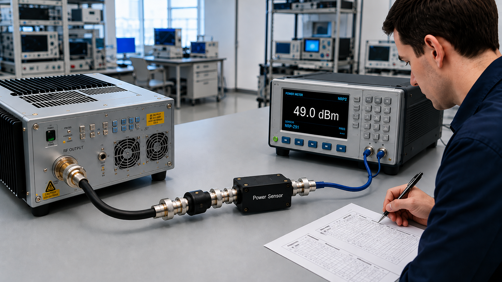
A power report can show the required RF output and still leave the acceptance result impossible to audit when the test cable loss compensation is not traceable. The problem is not always the meter reading itself. It may be unclear which losses were already corrected, which components were included in the correction chain, or which reference plane the final value represents.
This matters when a test path contains cables, adapters, attenuators, couplers, or a sampled measurement chain. A correction that is missing, applied twice, taken from the wrong frequency, or used outside its valid measurement boundary can change the reported acceptance result without changing the RF PA itself.
So what evidence should a buyer require before treating a corrected Pout value as valid RF PA acceptance data?
1.Why a Corrected Power Number Still Needs a Reference Plane
A power meter reports the RF power presented to its measurement point.
That measurement point is not automatically the PA output connector.
Depending on the setup, the sensor may be located:
- directly at the PA output;
- after a test cable;
- after an adapter or transition;
- on the sampled port of a directional coupler;
- after an attenuator;
- somewhere else in a calibrated measurement chain.
The reported value therefore needs a declared reference plane.
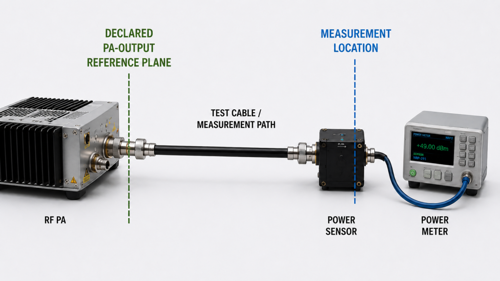
For RF PA acceptance, a useful report should distinguish at least:
- where the instrument actually measured;
- which reference plane the final Pout is intended to represent;
- which correction was used between those two points.
A corrected PA-port Pout is a value represented at the declared PA-output reference plane after the stated correction is applied. It should not be described as though the instrument measured directly at that connector when the sensor was located elsewhere.
This distinction becomes important when two reports use the same final wattage but represent different physical locations.
For example, these are not automatically equivalent:
- 100 W measured directly at the PA output;
- 100 W measured after a cable;
- 100 W corrected back to the PA output from a downstream measurement point;
- 100 W reported at the antenna end after installed feeder loss.
The number alone is not enough.
The report needs to state what that number represents.
Installed feeder loss is a separate system boundary from test-path correction. If the customer needs to evaluate the power available farther down the installed RF path, use the dedicated guidance on RF PA feeder cable loss before acceptance rather than treating test-fixture correction and installed feeder loss as the same quantity.
2.What Test-Path Loss Compensation Actually Corrects
“Cable-loss compensation” is often used as a convenient shorthand, but a real RF measurement setup may contain more than one type of path.
Do not treat every cable, coupler, attenuator, and adapter in the setup as one undifferentiated test cable loss.
The correction must correspond to the actual measurement architecture and the reference plane being reported.
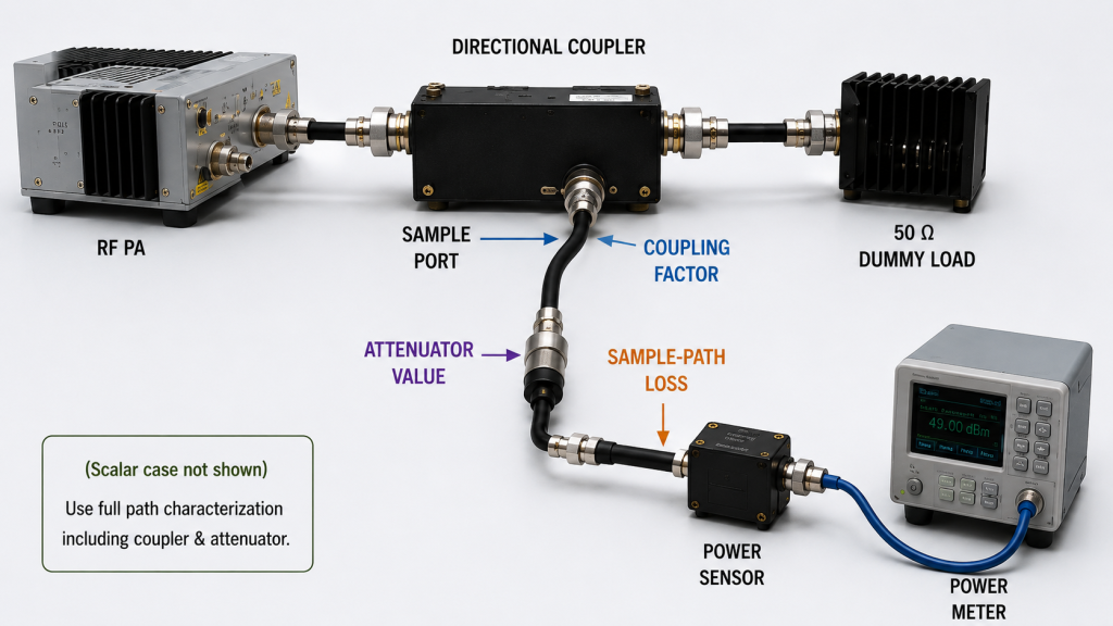
For example, a setup may contain:
- a high-power main RF path between the PA and load;
- a directional coupler in the mainline;
- a sampled measurement path from the coupler to the sensor;
- an attenuator in the sample path;
- adapters or connectors;
- instrument-specific calibration or correction data.
These components do not necessarily belong to one single scalar correction term.
A simplified scalar-loss example
Consider a simple, sufficiently matched measurement path in which the sensor is located after a characterized cable.
Assume:
- raw sensor reading: 49 dBm;
- characterized loss between the declared PA-output reference plane and the sensor: 1 dB.
In this simplified scalar case:
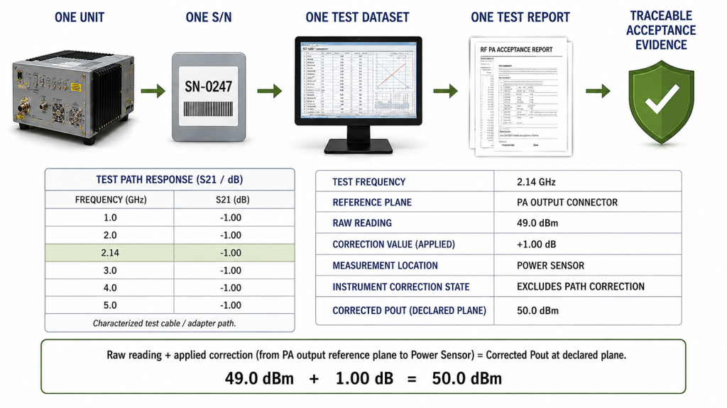
Corrected Pout = 49 dBm + 1 dB = 50 dBm
The corrected value represents the declared upstream reference plane.
This is an example calculation, not a universal RF correction rule.
It is valid only when the measurement architecture, characterized path loss, frequency, and mismatch conditions allow that scalar correction to represent the intended reference plane.
Where mismatch materially affects the measurement, simple scalar loss addition may not be sufficient. The correction method should match the measurement architecture and the calibration, characterized correction, or de-embedding approach being used.
A valid scalar path-loss correction also does not, by itself, remove mismatch or other measurement uncertainty. Where the acceptance margin is narrow, those uncertainty contributions should be considered separately rather than hidden inside one nominal cable-loss number.
Correction depends on where the power is sampled
If the measurement is taken from a directional coupler sample port, the correction may involve different quantities from a simple inline cable measurement.
Depending on the setup, the measurement record may need to account for:
- coupling factor;
- sample-path cable loss;
- attenuator value;
- adapter or fixture loss;
- frequency-dependent calibration data;
- instrument correction already enabled.
The purpose is not to create the largest possible correction.
The purpose is to trace the raw sensor reading to the reported reference plane using the correction that actually belongs to that measurement chain.
3.How Missing or Double Compensation Changes RF PA Acceptance
Correction errors can move the reported RF output even when the PA itself has not changed.
Four problems are especially important.
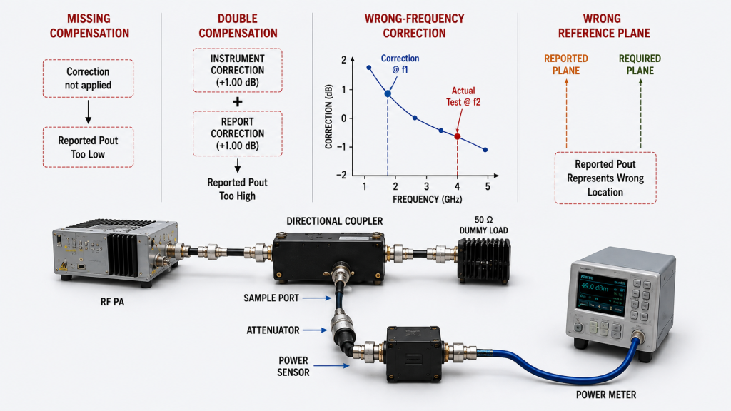
Missing compensation
If a valid test-path loss is not included where the acceptance result is supposed to represent an upstream reference plane, the reported Pout may be lower than the value represented at that plane.
This can make a compliant module appear to miss the required output.
Double compensation
The opposite error occurs when the same correction term is applied twice.
For example, a loss term may already be:
- entered into the power meter;
- embedded in calibration data;
- applied automatically by test software.
If the same term is then added again during report preparation, the corrected value can be overstated.
The report should therefore make clear whether each correction is:
- already active in the instrument;
- embedded in calibration or test-system data;
- applied later in software;
- added manually during report calculation.
The same correction term must not be counted twice.
A measurement chain may legitimately contain several different correction terms. The acceptance record should show how those terms combine without duplicating any one of them.
Wrong-frequency correction
RF cable loss, coupler behavior, attenuator performance, and other measurement-chain terms can vary with frequency.
A correction established at one frequency should not automatically be applied across the entire operating band unless the characterization supports that use.
Where frequency dependence is relevant, retain a correction table, calibration file, or characterized frequency range associated with the actual test points.
Wrong reference plane
Even a numerically correct correction can be wrong for acceptance if it represents the wrong location.
A value corrected to the PA output connector is not automatically the same as:
- cabinet output;
- feeder input;
- feeder output;
- antenna input.
The reference plane must follow the acceptance requirement.
Correction failure modes
| Observation | Possible correction problem | Evidence to check | What it can affect |
|---|---|---|---|
| Reported Pout is unexpectedly low | Required path loss was not applied | Raw reading, reference plane, correction state | Pass/fail result |
| Reported Pout is unexpectedly high | Same correction may have been applied twice | Instrument settings, test software, report calculation | Overstated corrected Pout |
| Error changes with frequency | Correction may not match the actual frequency | Frequency-specific loss, calibration data, or stated validity range | Full-band acceptance |
| Two reports disagree | Different correction chains or reference planes may have been used | Measurement location, correction source, represented plane | Supplier or retest comparability |
| Final value cannot be reconstructed | Raw reading or correction source is missing | Raw data, correction table, instrument state | Auditability |
| Field result differs from factory result | Test boundaries may not be equivalent | Path configuration, reference plane, load and correction method | Retest interpretation |
The goal of this table is not to assign a root cause from one number.
It is to identify what evidence should be checked before concluding that the PA itself changed.
4.Why Two Corrected RF PA Results May Still Not Be Comparable
Applying a correction does not automatically make two RF PA test results comparable.
For a direct comparison, the reported values should represent equivalent measurement boundaries.
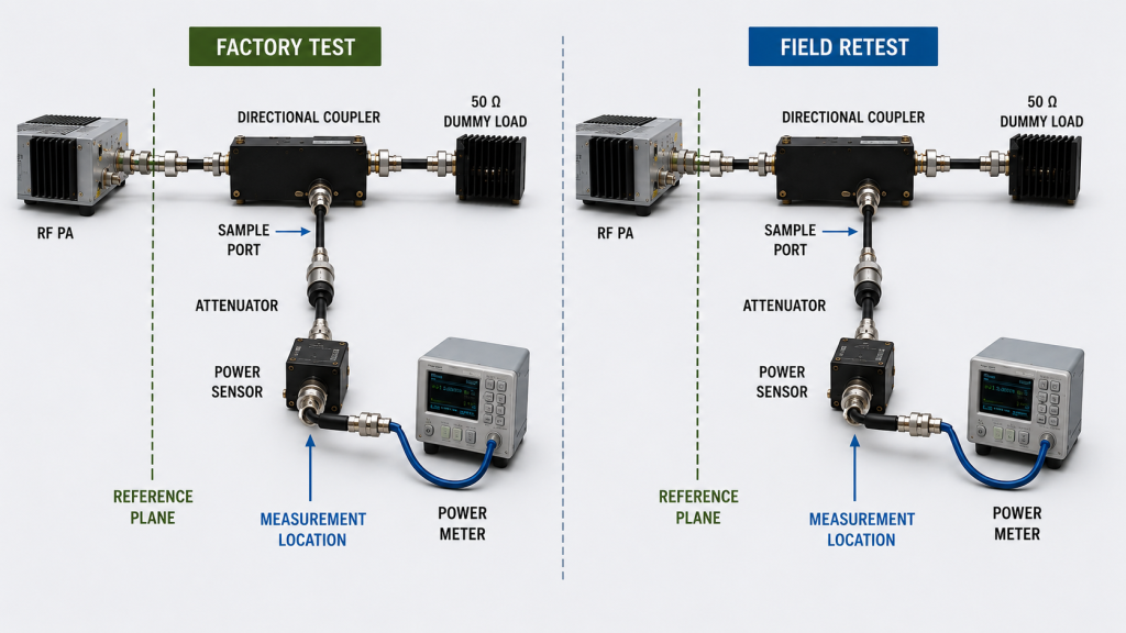
At minimum, compare:
- frequency;
- represented output reference plane;
- Pin or defined drive condition;
- load condition;
- relevant DC condition;
- thermal state where applicable;
- measurement architecture;
- correction method.
Two corrected Pout values are directly comparable only when their represented reference plane and relevant test conditions are equivalent and their correction methods are valid for each setup.
This matters during:
- factory acceptance;
- customer incoming inspection;
- field retest;
- repair verification;
- supplier comparison.
For example, a factory report may correct a calibrated measurement chain back to the PA output connector.
A later field test may use:
- another cable;
- another sensor;
- a different attenuator;
- another adapter;
- another reference plane.
If the two setups are not documented, a difference in corrected Pout cannot automatically be assigned to the PA.
Do not “fix” the number before preserving the evidence
If a retest disagrees with the factory report, first preserve:
- raw reading;
- test frequency;
- measurement location;
- stated reference plane;
- correction values;
- correction source;
- instrument correction state;
- load condition;
- Pin or drive condition;
- relevant DC condition;
- unit S/N.
Then compare the two measurement chains.
Changing a correction value simply to make the two reports agree destroys the evidence needed to understand why they differed.
5.What Correction Evidence Should an RF PA Acceptance Report Show?
A final corrected Pout number is easier to trust when the path from the raw measurement to the reported reference plane can be reconstructed.
A useful acceptance record can include:
| Evidence item | What should be recorded | Why it matters |
|---|---|---|
| Unit identity | Module S/N when unit-level acceptance is required | Links the result to the tested unit |
| Test frequency | Exact test point | Correction may be frequency dependent |
| Pin / drive condition | Defined input condition | Keeps the RF operating point comparable |
| Measurement location | Where the sensor or sample point actually sits | Shows where the raw value originated |
| Declared reference plane | Where corrected Pout is represented | Defines what the acceptance number means |
| Raw reading | Instrument value before report-level correction | Allows later reconstruction |
| Correction source | Measured or characterized path data, calibration file, or other identified correction source | Shows where the correction came from and whether it can be traced to the stated measurement path |
| Correction value | Applicable loss, coupling, attenuation, or other defined term | Connects raw and corrected data |
| Correction frequency / validity | Frequency or frequency range over which the stated correction is valid | Prevents unsupported reuse across unverified test points |
| Instrument correction state | Whether compensation is already enabled in the instrument or test system | Prevents double counting |
| Additional report correction | Any later calculation applied outside the instrument | Completes the audit trail |
| Corrected Pout | Final value represented at the declared plane | Supports the acceptance comparison |
| Load condition | Defined load or test boundary | Prevents comparison across different RF conditions |
| Test time or dataset ID | Timestamp or traceable test record | Supports reconstruction and report traceability |
Where a correction value comes from a characterized cable, fixture, attenuator, coupler, or measurement chain, the record should identify the applicable assembly or path closely enough to reproduce the calculation.
Where project traceability requires it, that record may also include an assembly ID, characterization date, calibration reference, or stated validity period.
A number such as “0.8 dB correction” is less useful if the report does not show:
- what that 0.8 dB represents;
- which frequency or frequency range it applies to;
- where it was measured or characterized;
- whether it was already active elsewhere in the test system.
Unit-linked evidence when required
When acceptance is required per delivered unit, keep the correction record and final result linked to that unit S/N.
A useful traceability chain is:
One Unit → One S/N → One Test Dataset → One Test Report → Traceable Acceptance Evidence
This is an evidence structure for projects that require unit-level acceptance.
It is not a statement that every RF PA project must use the same reporting format.
What Should the RFQ Define?
If corrected RF output is part of the acceptance requirement, the RFQ should define more than a target wattage.
The customer should specify, where relevant:
- operating frequencies or test points;
- required Pout;
- Pout reference plane;
- Pin or drive condition;
- measurement location;
- measurement method;
- test-path configuration;
- correction source;
- correction method;
- correction frequency or validity range;
- whether corrections may be applied in the instrument or report;
- load condition;
- required raw data;
- required corrected data;
- unit-level traceability;
- required test-report format.
This prevents one supplier from reporting a raw sensor value while another reports a corrected PA-port value and calling the two numbers equivalent.
When corrected Pout evidence is part of module approval, define the required output reference plane, measurement method, correction basis, frequency points, and unit-level report requirement before selecting the RF PA module.
FAQ
Is a power meter reading enough for RF PA approval?
Not by itself when the acceptance requirement applies to a different reference plane.
The report should show where the instrument measured and whether the final Pout is a raw reading or a corrected value represented at another defined plane.
Does adding cable loss always give the correct PA-port Pout?
No.
Adding a characterized path loss can be valid in a sufficiently matched scalar measurement case, but it is not a universal correction rule.
The correction must match the actual measurement architecture, frequency, reference plane, and calibration or de-embedding method being used.
Where mismatch materially affects the measurement, a simple scalar loss addition may not be sufficient.
Can one correction value be used across the full frequency range?
Only if the characterization or calibration supports that use.
Cable loss, coupling factor, attenuator behavior, and other measurement-chain terms can vary with frequency.
For full-band acceptance, the correction should be valid for the actual test frequencies or for a characterized frequency range that includes them.
Why should raw and corrected results both be retained?
Because the raw reading and the correction record allow the final reported Pout to be reconstructed.
If only the corrected number remains, it may be impossible to determine later whether the result came from:
- the correct measurement plane;
- the correct frequency;
- the correct correction source;
- a missing correction;
- a double-applied correction.
Conclusion
A corrected RF PA output value is trustworthy for acceptance only when the report shows how the raw measurement was translated to the declared reference plane using a correction chain that is valid for the actual measurement architecture, frequency, and test condition.
Test-path loss compensation is not simply a rule to “add cable dB back.” The report should distinguish the measurement location from the represented reference plane, identify the source and state of each correction term, and make sure the same term is not counted twice.
Where a simple scalar correction is valid, it can translate a downstream reading to the required reference plane. Where mismatch or a more complex sampled measurement chain materially affects the result, the correction method must match that measurement architecture rather than relying on an undifferentiated cable-loss number.
The most defensible acceptance evidence therefore preserves:
Raw Reading → Measurement Location → Correction Source → Correction Chain Without Double Counting → Corrected Pout → Declared Reference Plane
When unit-level acceptance is required, that evidence should also remain linked to the module S/N and its test record.
For an RFQ that depends on corrected RF output data, provide the target frequencies, required Pout and reference plane, measurement location, test-path configuration, correction source, correction method, correction validity range, load condition, and required report traceability.
Contact RF SKYPOWER with these acceptance requirements before the test boundary is finalized.