










A full-power RF PA test can look convincing when the amplifier reaches its target output at one favorable frequency. The problem is that a clean center-frequency result—or even a smooth small-signal curve—does not show whether every required operating point remains acceptable at the real input drive, signal condition, DC load, thermal state, and protection boundary.
A weak frequency can appear because the PA itself changes, actual Pin is different, the load or measurement boundary changed, or thermal and protection conditions were not held comparable.
Before approving the sweep, the buyer therefore needs to answer one question: what conditions and evidence make every full-power frequency point comparable enough to support a real pass/fail decision?
1. What Does a Full-Power RF PA Frequency Sweep Actually Prove?
A full-power frequency sweep shows how an RF power amplifier behaves across the project-defined operating frequencies at the required high-power operating condition.
In this article, full power means the project-defined required or rated condition under a stated:
- Signal type and power definition
- Pin rule
- Pout requirement
- DC supply condition
- RF load
- Duty cycle
- Cooling condition
- Thermal state
- Protection boundary
It does not mean driving the PA toward an uncontrolled maximum or saturation point simply to obtain the highest possible output.
Depending on the project, the specified condition may involve:
- CW operation
- Pulsed RF
- A defined modulated waveform
- Average power
- Peak or peak-envelope power where applicable
- Another explicitly agreed power metric
A statement such as “100 W full power” is incomplete unless the signal and power definition are also stated.
What Does “Swept-Frequency” Mean Here?
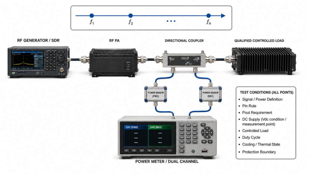
For high-power PA acceptance, a frequency sweep may use a controlled sequence of discrete frequency points with a defined settling or dwell condition at each point.
Typical points may include:
- Lower project edge
- Critical operating channels
- Mid-band points
- Upper project edge
A continuous automated sweep is a different measurement implementation. It should only be treated as equivalent when:
- The RF source follows the commanded sweep correctly
- The PA responds without unaccounted dynamic effects
- The load and measurement chain remain valid
- Protection monitoring captures the required behavior
- Data acquisition has sufficient timing and bandwidth
- The acceptance requirement does not depend on a per-point dwell, stabilized thermal state, protection recovery interval, or another time-dependent condition that the continuous sweep does not reproduce
If those time-dependent conditions matter, use defined stepped or list points—or separately repeat critical frequencies under the required stabilized state.
The key question is not whether the trace is called a sweep, but whether each reported point represents the operating condition required by the RFQ.
2. Why Can’t Small-Signal Sweeps Prove Full-Power Performance?
Small-signal measurements are useful for checking gain shape, frequency response, and basic RF behavior at relatively low drive.
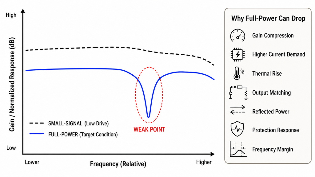
They do not automatically predict what happens at the project-defined high-power condition, where additional effects can include:
- Gain compression
- Device current demand
- DC supply interaction
- Thermal rise
- Output matching behavior
- Reflected-power sensitivity
- Protection response
- Frequency-dependent output margin
A PA can therefore show a smooth small-signal response and still develop a weak point during a full-power frequency test.
When Pin and Pout use the same signal and power definition and are expressed in dBm:
Power Gain (dB) = Pout (dBm) − Pin (dBm)
Both values must refer to clearly defined measurement planes.
If Pout changes while Pin also changes, the result does not represent PA gain behavior alone.
Detailed comparison between low-drive and high-power gain belongs in the small-signal and large-signal RF PA gain review.
A small-signal sweep can support diagnosis, but it cannot replace full-power evidence when the RFQ requires high-power operation across the band.
3. What Test Boundary Must Be Fixed Before the Sweep?
A full-power curve is meaningful only when the conditions behind every point are defined.
Full-Power Test Boundary Table
| Test Item | What Must Be Defined | Why It Matters |
|---|---|---|
| Signal / power definition | CW, pulsed, or required waveform; average, peak, PEP, or other agreed metric | Prevents different signal and power definitions from being treated as the same “full-power” condition |
| Frequency range | Project-defined lower/upper limits and required channels | Prevents favorable frequencies from replacing the actual operating range |
| Frequency-point plan | Test points, step logic, dwell or settling condition | Makes the sweep reproducible |
| Pin | Actual input reference plane, drive rule, and allowed drive boundary | Separates PA behavior from source-path variation or excessive drive correction |
| Pout | Defined PA output reference plane and required output criterion | Prevents cable or fixture loss from being mixed into PA output |
| DC supply | Vdc range and measurement point | Keeps power and current results comparable |
| RF load | Qualified controlled load and load path | Prevents fixture problems from becoming PA results |
| Reflection requirement | VSWR or return loss, method, frequency, and reference plane | Defines the permitted load mismatch |
| High-power FWD/REV evidence | Directional measurement point and required data | Shows powered load behavior separately from a reflection specification |
| Duty cycle | CW or defined intermittent operation | Defines electrical and thermal loading |
| Cooling | Required heatsink, airflow, liquid cooling, or fixture | Keeps thermal conditions controlled |
| Thermal state | Cold, transition, stabilized hot, or another defined condition | Prevents cold-only data from representing hot operation |
| Protection behavior | Alarm, foldback, derating, shutdown, and recovery criteria | Defines acceptable protection behavior |
| Test duration | Per-point dwell and total operating condition where relevant | Defines what time-dependent behavior the evidence can support |
Separate the Module Sweep From the Installed RF Path
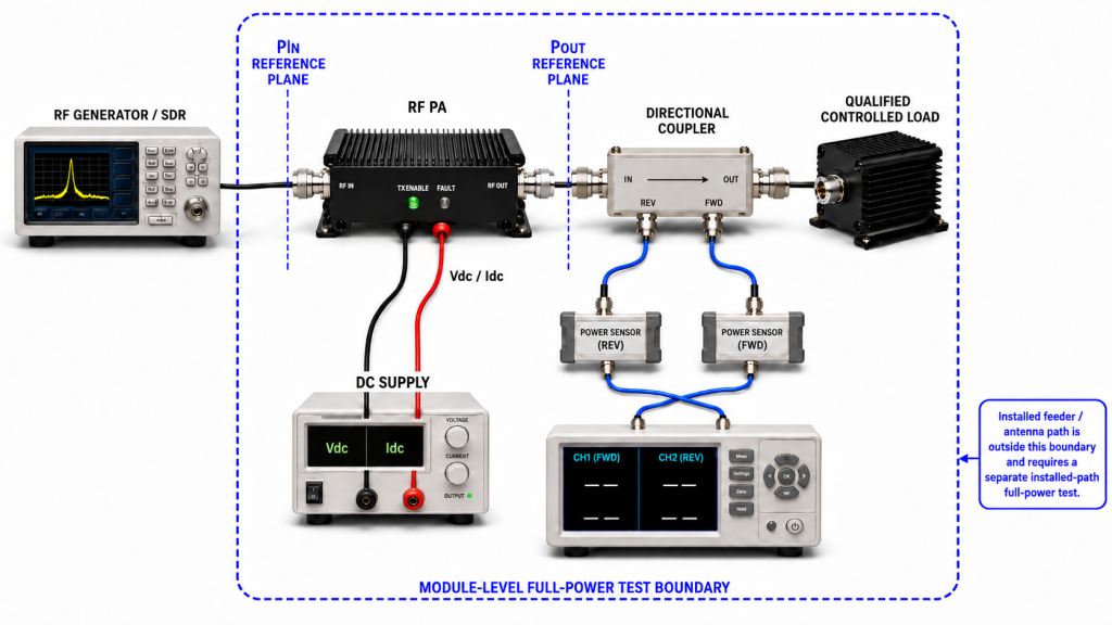
A module-level full-power sweep should establish module-level PA behavior under the defined controlled-load condition.
The load, high-power jumper, connectors, attenuators or couplers, power sensors, and measurement corrections must be suitable for the required frequency and power.
Where the dummy-load cable or high-power load path itself needs qualification, use the separate dummy-load cable qualification review.
If the project also requires the final feeder and antenna chain to be accepted, treat that as a separate installed-path test boundary.
Do not combine PA module behavior, feeder insertion loss, antenna mismatch, and installed connector behavior into one curve and call the result “PA full-power performance.”
4. How Should Frequency Points and Input Drive Be Defined?
A useful sweep needs both a frequency plan and a drive rule.
The plan should cover, as applicable:
- Required lower edge
- Required upper edge
- Critical operating channels
- Known transition regions
- Intermediate points needed to represent the required range
Where band-edge behavior needs deeper diagnosis, use the separate RF PA band-edge verification review.
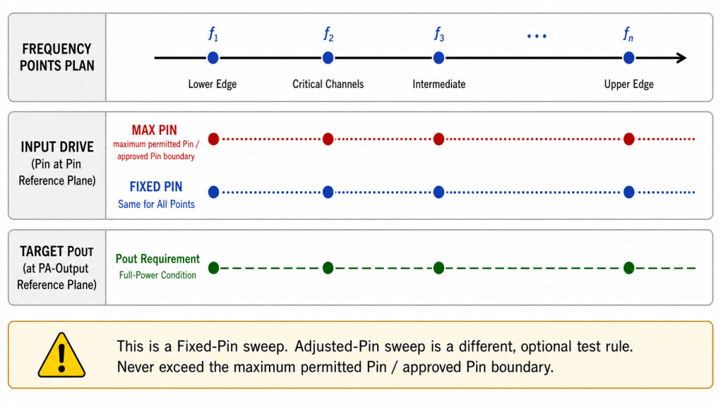
Define the Pin Rule Before the Sweep
For every frequency point, state whether Pin is:
A. Held at one calibrated value, or
B. Adjusted to reach a target Pout.
Both approaches can be valid, but they answer different questions.
Fixed-Pin Sweep
A fixed-Pin sweep is useful when the buyer wants to observe PA behavior under comparable input drive.
If Pout falls at one frequency while actual Pin remains comparable, frequency-dependent PA behavior becomes more relevant.
The RFQ should still define the permitted Pin tolerance.
Adjusted-Pin Sweep
An adjusted-Pin test may be appropriate when the operating system intentionally controls drive to reach a target output.
The report must record the actual Pin at every point and define:
- Permitted Pin range
- Maximum allowed Pin
- Target Pout or minimum Pout
- Minimum large-signal gain where required
Otherwise, a flat Pout curve can hide excessive required drive.
A frequency point should not pass merely because target Pout was reached if the required Pin exceeds the approved drive boundary.
Actual Pin should be measured or established at the PA input reference plane, not assumed from the nominal source setting.
If Pin is derived from a measurement elsewhere in the input path, record the calibrated or characterized correction used to represent the PA-input reference plane.
Detailed source-path verification belongs in the RF PA input power measurement review.
Do Not Change Multiple Boundaries at Once
If one frequency point appears weak, preserve the original condition before changing Pin, Vdc, cooling, load, measurement correction, or protection settings.
Change one intentional variable at a time so that the symptom is not removed before the cause can be isolated.
5. What Evidence Should Be Recorded at Each Full-Power Point?
A full-power sweep becomes useful acceptance evidence only when every reported point is traceable to its operating and measurement conditions.
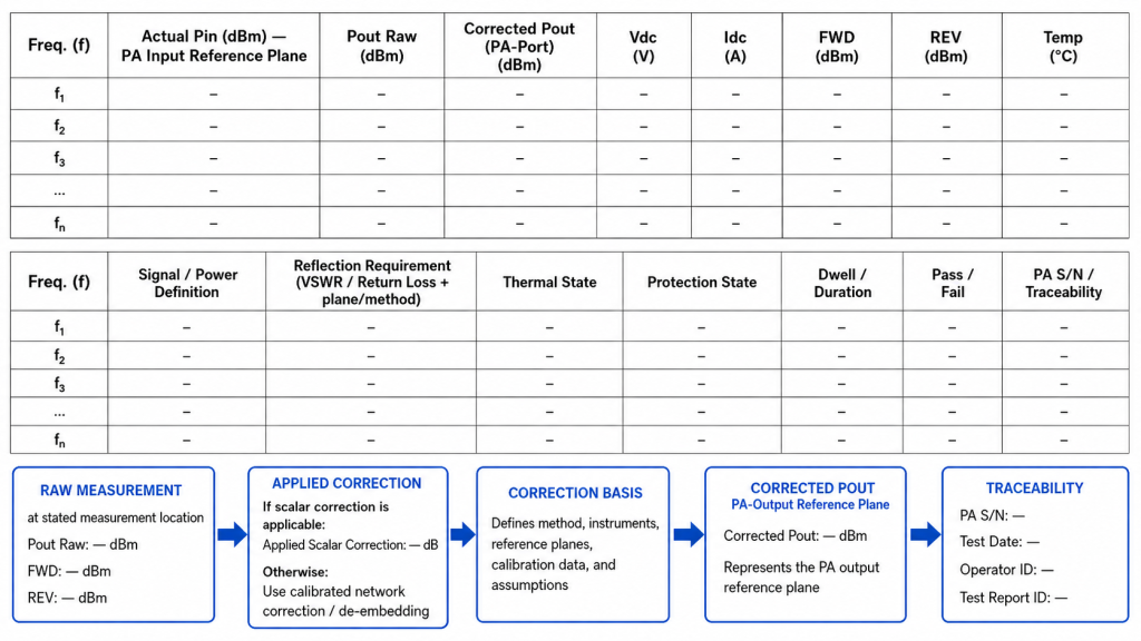
Per-Frequency Evidence Table
| Evidence | What to Record | What It Helps Prove |
|---|---|---|
| Frequency | Actual test frequency | Which operating point was evaluated |
| Signal / power definition | Required waveform and applicable power metric | Whether Pin and Pout refer to the intended signal |
| Actual Pin | PA-input value at the defined reference plane, including input-path correction basis where required | Whether drive was comparable and within its allowed boundary |
| Pout | Raw and/or corrected value with stated PA output plane | Whether required PA output was met |
| Correction basis | Characterized cable/attenuator/coupler correction or de-embedding method where used | How the reported reference plane was obtained |
| Vdc | Voltage at the required measurement point | Whether supply conditions remained within the test boundary |
| Idc | PA current at the operating point | DC behavior across frequency |
| Reflection requirement | VSWR or return loss at defined plane/method where required | Whether mismatch remained within the approved boundary |
| FWD/REV evidence | Directional high-power reading at the stated measurement plane where required | Powered load behavior |
| Thermal state | Cold, transition, stabilized hot, or another defined state | Whether temperature affected the result |
| Protection state | Alarm, foldback, derating, shutdown, recovery status | Whether the operating point remained acceptable |
| Dwell / duration | Relevant time at the point or state | Whether the required time-dependent condition was represented |
| Traceability | PA S/N, configuration, and test setup | Whether the result can be reproduced |
Keep Raw and Corrected Values Distinct
If the power sensor is not located directly at the PA output reference plane, record:
- Raw measured value
- Measurement location
- Applied correction
- Correction method or basis
- Corrected Pout
- Reference plane represented by that corrected value
Do not subtract a nominal cable-loss value and present the result as though it were directly measured at the PA port.
Where mismatch materially affects the measurement, a simple scalar loss correction may not be sufficient. Use the calibration, characterized network correction, or de-embedding method appropriate to the measurement architecture.
The same principle applies to Pin when the PA-input value is derived from a measurement elsewhere in the source path.
Reflection Requirement Is Not the Same as FWD/REV Evidence
VSWR or return loss describes an agreed mismatch requirement at a defined plane and measurement method.
FWD and REV power are directional high-power operating measurements taken at a stated measurement plane.
They may be related, but they are not interchangeable acceptance numbers.
Make the Report S/N-Linked
For procurement and production acceptance, preserve at least:
- PA S/N
- Hardware/configuration revision where relevant
- Frequency-point list
- Test boundary
- Measurement setup
- Pass/fail result
This prevents a representative sample curve from being mistaken for evidence covering every delivered unit.
When full-power sweep evidence is part of module approval, define the required frequency points, signal and power definition, PA-port output, actual Pin and permitted drive boundary, DC condition, load boundary, thermal state, protection behavior, and S/N-linked report before selecting custom RF power amplifier modules.
6. How Should Weak Frequency Points Be Interpreted and Rechecked Hot?
A weak point on the sweep is an observation, not a root cause.
Before assigning the result to the PA, confirm that the following were comparable:
- Signal and power definition
- Actual Pin
- Permitted Pin boundary
- PA output reference plane
- Load condition
- DC supply
- Duty cycle
- Cooling
- Thermal state
- Measurement correction
- Protection configuration
Typical patterns include:
- Pout decreases while actual Pin remains within the same boundary: frequency-dependent PA behavior becomes more relevant.
- Pout decreases while Pin also decreases: source or input-path variation should be isolated first.
- Target Pout is maintained only by materially increasing Pin: reduced large-signal gain or drive margin becomes relevant.
- Pout changes while REV rises: load or mismatch behavior becomes more relevant.
- Pout drops and protection activates: protection response may be part of the result.
- Cold result passes but stabilized hot result drops: thermal state is part of the performance boundary.
- Idc changes significantly with the RF result: DC behavior should be included in the diagnosis.
Recheck Important Weak Points at the Required Thermal State
If the RFQ requires sustained or hot-state operation, a cold sweep is not sufficient evidence.
A practical sequence is:
- Establish the initial or cold sweep if required.
- Operate the PA under the defined thermal-loading condition.
- Reach the project-defined hot-state criterion.
- Repeat the required full-power frequency points.
- Compare signal condition, Pin, Pout, Vdc, Idc, load evidence, and protection state.
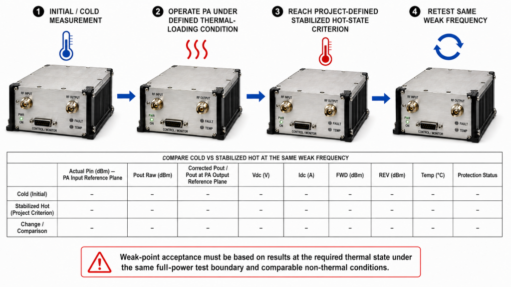
Do not assume that a fixed number of minutes represents thermal stabilization for every PA, heatsink, cabinet, duty cycle, or cooling architecture.
For hot-state Pout acceptance, use the dedicated RF PA thermal soak review to define the stabilization boundary, Pout reference plane, applicable RF correction, and directly comparable cold-to-hot conditions when thermal drift is also part of the acceptance requirement.
Detailed frequency-dependent thermal behavior belongs in the RF PA frequency and temperature review.
Post-Burn-In Repetition Is Conditional
A post-burn-in full-power resweep should be included only when the project or production acceptance plan requires before/after comparison.
If required, define:
- Burn-in condition
- Duration
- Load
- Signal condition
- Thermal state
- Pre/post frequency points
- Permitted change
- Required S/N-linked evidence
Application Example: Remote or Harsh-Site Systems
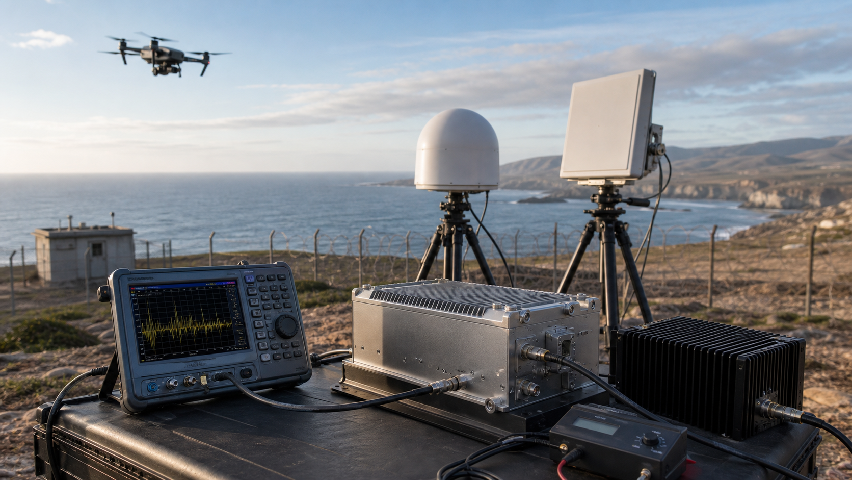
For border, coastal, perimeter, or other remote C-UAS deployments, full-power evidence may be especially important because service access can be limited and the operating environment may add thermal, power, or installation stress.
The site type, however, does not replace the test boundary. Results should still be judged by the defined frequencies, signal condition, Pin/Pout, load, DC condition, thermal state, protection behavior, and measurement evidence.
7. What Should the RFQ Define for Full-Power Sweep Approval?
An RFQ should not simply request:
- “Full-band test”
- “100 W across band”
- “Gain flatness test”
- “Burn-in test”
- “VSWR test”
Each requirement needs a defined operating condition, measurement boundary, and pass criterion.
RFQ Full-Power Sweep Checklist
| RFQ Item | What to Define | Why It Matters | Expected Evidence |
|---|---|---|---|
| Required frequency range | Exact project operating range | Defines what “full band” means | Approved frequency list |
| Frequency-point plan | Edges, critical channels, intermediate points, dwell or settling rule | Prevents favorable-point testing | Point-by-point sweep record |
| Full-power operating condition | Signal type, power definition, target or minimum Pout, and applicable operating state | Defines what “full power” means | Point-by-point result using the stated power definition |
| Pin rule | Fixed calibrated Pin, or target-Pout control with permitted Pin range / maximum Pin and minimum gain if required | Prevents drive correction from hiding weak large-signal behavior | Actual Pin and Pout at every required frequency |
| PA input reference plane | Exact location represented by Pin and any input-path correction basis | Separates source-chain loss from PA drive | Labeled Pin record and correction basis |
| PA output reference plane | Exact location represented by Pout | Prevents downstream loss from being called PA output | Raw/corrected Pout record |
| Load boundary | Qualified dummy load or other approved controlled load | Establishes module-level test condition | Load/setup definition |
| Reflection requirement | VSWR or return loss, method and plane | Defines permitted mismatch | Calibrated reflection evidence |
| High-power FWD/REV evidence | Required directional measurements and plane | Shows powered load behavior | FWD/REV record |
| DC condition | Vdc range and measurement point | Keeps current/output results comparable | Vdc/Idc record |
| Duty cycle | CW or stated intermittent condition | Defines electrical and thermal loading | Operating-state record |
| Thermal criterion | Cold, transition, stabilized hot, or another defined state | Prevents cold-only approval when hot operation matters | Temperature/time-linked evidence |
| Protection behavior | Allowed alarm, foldback, derating, shutdown, recovery | Establishes pass/fail behavior | Protection log |
| Post-burn-in repeat | Required only if part of project acceptance | Prevents an optional test from becoming universal | S/N-linked pre/post record |
| Traceability | S/N, setup, configuration, date | Makes the evidence reproducible | S/N-linked report |
A successful center-frequency test remains evidence for that tested frequency and condition. It should not be extended to untested band edges or operating channels.
Likewise, a small-signal sweep cannot substitute for required high-power evidence, and an adjusted-Pin test should not pass when target Pout is reached only by exceeding the approved drive boundary.
A full-power sweep is also not the entire shipment-release decision. Broader control, protection, thermal, traceability, mechanical, and project-specific requirements belong in the C-UAS RF PA acceptance checklist.
FAQ
Is a full-power RF PA frequency sweep the same as a small-signal sweep?
No.
A small-signal sweep characterizes RF behavior at relatively low drive. A full-power sweep evaluates the PA at the project-defined high-power condition, where gain compression, DC current, thermal state, load behavior, and protection response may change the result.
Small-signal data can support diagnosis, but it does not replace required full-power evidence.
Should Pin stay fixed or be adjusted at each frequency point?
Either method can be valid if it matches the test objective and is declared before testing.
A fixed-Pin sweep is useful for observing PA behavior under comparable input drive.
An adjusted-Pin sweep may be appropriate when the operating system controls drive to reach a target output, but the actual Pin and permitted Pin boundary must both be defined. If minimum large-signal gain is part of acceptance, that limit should also be stated.
A Pout-only curve cannot distinguish acceptable frequency response from excessive drive correction.
What evidence is required before a full-power sweep can support approval?
The report should identify the required frequency points and record the relevant signal and power definition, actual Pin, permitted drive boundary, Pout, input and output reference planes, correction basis, Vdc, Idc, load or reflection condition, thermal state, protection behavior, dwell or duration, and PA S/N.
The evidence must also show the pass/fail boundary at each required point.
Conclusion
A full-power RF PA test does not prove full-band performance simply because the PA passes at one center frequency or produces a smooth small-signal curve.
A defensible swept-frequency result requires a defined signal and power condition, qualified controlled load, declared frequency-point plan, explicit Pin rule and drive boundary, consistent input and output reference planes, comparable DC and thermal conditions, and per-point RF and protection evidence.
If one frequency appears weak, confirm actual Pin, permitted drive range, Pout reference plane, load condition, measurement correction, Vdc, thermal state, and protection behavior before assigning a root cause. A flat Pout curve is also insufficient if target output was achieved only by exceeding the approved input-drive boundary.
If continuous sweeping is used, it must reproduce the operating state required by the acceptance test. Where per-point dwell, thermal stabilization, protection recovery, or another time-dependent condition matters, critical points should be tested under that defined state.
The RFQ should state which frequencies must pass, how full power is defined, what signal and power metric apply, whether Pin is fixed or adjusted, the permitted Pin range, where Pin and Pout are referenced, what load and reflection boundaries apply, which FWD/REV or protection evidence is required, and what S/N-linked report supports acceptance.
For an RFQ review, contact RF SKYPOWER with your required frequency range, frequency-point list, signal type and power definition, target PA-port output, input-drive rule and maximum permitted Pin, DC supply range, duty cycle, controlled-load condition, PA input and output reference planes, VSWR or return-loss requirement, required FWD/REV evidence, cooling method, hot-state criterion, protection limits, post-burn-in requirement if applicable, and required S/N-linked test report.