










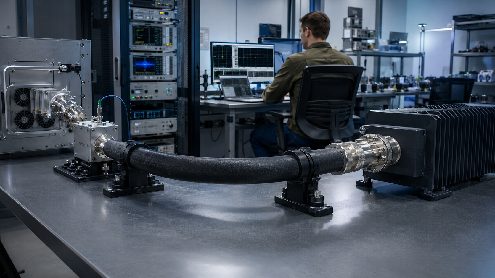
A dummy load cable is qualified only when the exact high-power jumper, test boundaries and operating conditions are known. Before relying on an RF PA result, verify the jumper’s return loss and insertion loss, its power and duty-cycle rating, the connectors and adapters, mechanical support, temperature and measurement planes.
A cable that passes a low-power test is not automatically suitable for sustained full-power operation. Likewise, a stable PA-side reading does not by itself prove that the dummy-load input receives the expected power or that the load condition is acceptable.
1. What a Dummy Load Cable Must Prove in RF PA Testing
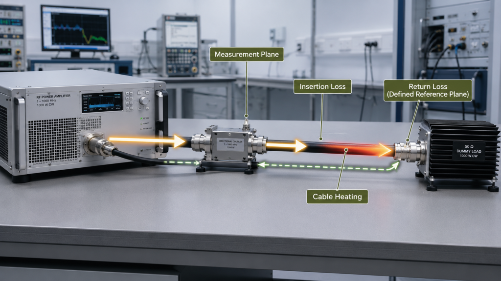
Here, a dummy-load cable means the main high-power coaxial jumper carrying RF energy toward a dummy load. It may sit between the PA and a directional coupler, or between the coupler and the load. This is separate from a coupler’s low-power sample cable, a power-sensor cable, a signal-generator input lead, an installed antenna feeder or a DC cable.
Because the jumper may sit on either side of the coupler, identify its position before interpreting power readings.
The qualification should establish three distinct things:
- Load-path behavior: the impedance and reflection presented through the cable assembly under the stated test condition.
- Power delivery: the power lost between the stated planes and the heating associated with the applied RF power.
- Measurement meaning: which value is raw, which is corrected, and which physical plane the reported result represents.
A suitable jumper needs evidence for the exact assembly, not just a nominal 50 Ω label or DC continuity. Record its manufacturer and model, assembly ID, length, connector and adapter combination, frequency range, power rating, duty-cycle conditions, bend limits, support condition and relevant mating history.
Cable qualification applies to that assembly and stated setup. It does not approve the PA, directional coupler, dummy load, low-power measurement chain or complete RF test system.
2. Where the Cable Sits in the Test and Measurement Planes
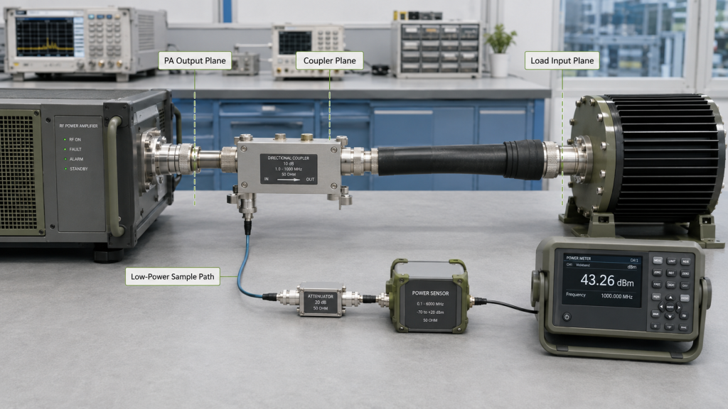
Name the physical reference plane for every power or reflection result. Possible planes include the PA output connector, coupler input or output, jumper input, dummy-load input, sensor input or spectrum-analyzer input.
For a cable before the coupler, state whether the result is measured at the PA output, the coupler plane, or corrected to another specified plane. For a cable after the coupler, distinguish the coupler’s forward-power plane from the load-input plane. The load receives less power than the upstream reading when the intervening path has insertion loss; the amount must come from applicable measurement or characterization data.
A coupler’s physical location alone does not show which plane the displayed result represents. Preserve the raw instrument reading, correction source and state, corrected value, and plane represented by that value. Do not apply the same correction twice.
The coupler sample path is a different measurement chain from the high-power jumper. Its cable, attenuator, coupling factor, sensor and corrections should be identified separately where they affect the result. The reported value depends on the correction chain and the reference plane it represents; test cable loss compensation guidance explains how to compare cable, adapter and attenuator corrections with that value.
For coupler-derived REV and VSWR, finite directivity allows forward leakage to add vectorially to the reverse sample, so cable phase changes can alter the indication even when the load’s reflection magnitude is unchanged. Ordinary scalar cable-loss and coupling-factor corrections do not remove this error. Record the applicable coupler directivity by frequency and account for the resulting measurement uncertainty before interpreting a REV or VSWR change as a change in mismatch.
The calibration plane should be placed at the intended cable reference plane. If adapters or fixtures remain between the calibration plane and the cable, identify them and include their effect in the test boundary.
3. How to Qualify a High-Power Dummy Load Cable
Start with the exact cable assembly and the frequencies and operating conditions required by the test plan. Use measurement limits and equipment specifications that apply to the project; do not invent universal return-loss, insertion-loss, temperature or power thresholds.
Cable-only return loss
Use a calibrated VNA and state both calibration planes and the far-end condition. Label a result “cable-only S11” only when measured at the stated input plane with the far end connected to the VNA’s calibrated, matched second port or, if that setup is unavailable, a characterized matched termination whose known residual reflection is included in the test boundary; record the termination and reference plane. Otherwise, label and report the actual assembled-path condition: an open end or mismatched load can dominate the input reflection. A one-port measurement with the dummy load connected is a separate cable-plus-dummy-load or assembled-path reflection result at the stated input plane; it describes the combined cable and load and does not isolate cable return loss.
Insertion loss
Measure cable-only S21 through the calibrated two-port setup at the project’s required frequencies, including the relevant low, middle, high and band-edge points. Record cable temperature, connector and adapter configuration, cable length, calibration planes and raw or corrected status. Do not extend one frequency’s loss value across a wider band unless the characterization supports it.
Power and operating conditions
The usable rating of the path is limited by the lowest applicable rating among the cable, connectors, adapters, coupler and dummy-load input. Check the rating under the actual frequency, average or CW power, peak power where relevant, duty cycle, cooling, ambient temperature, mismatch condition and test duration. A rating under a matched laboratory condition does not automatically establish suitability under a different reflected-power or thermal condition.
For a permanently installed feeder, use RF feeder cable qualification to select the model and route for the required frequency, length and operating conditions.
4. How Electrical Length and Residual Mismatch Change Results
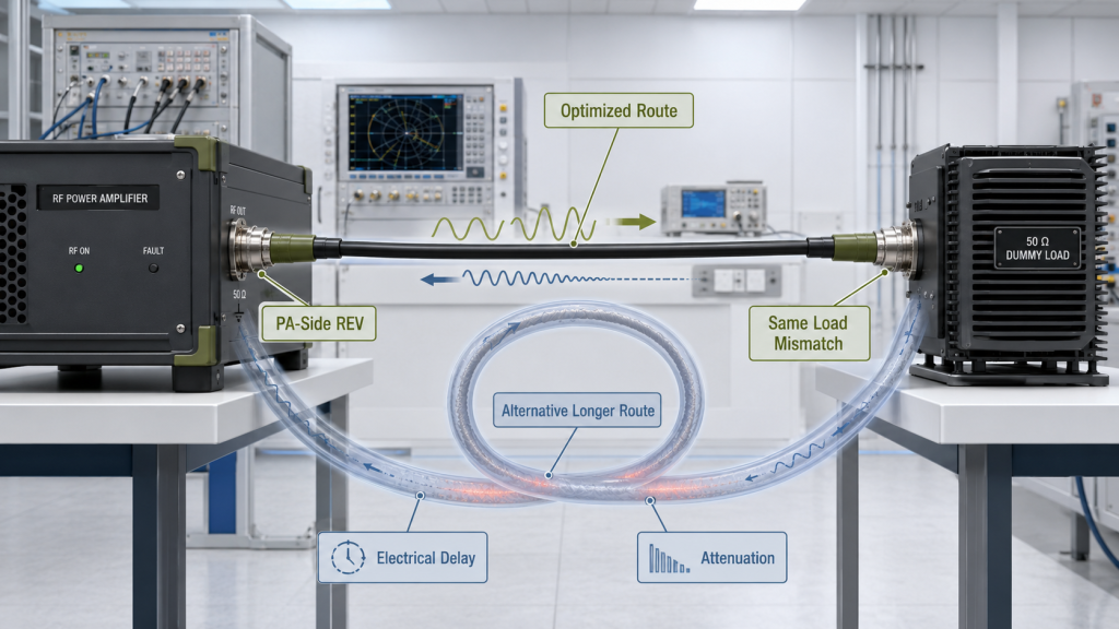
Cable length does not automatically create a VSWR problem. In an ideally matched path, additional cable length adds attenuation, electrical delay and heat dissipation. When a real path contains a reflection from a cable discontinuity, connector, adapter, coupler or load, electrical length can change the reflected-wave phase at the PA plane.
Attenuation and impedance discontinuities are separate cable effects. A matched lossy cable can reduce power delivered to the dummy load and dissipate heat without adding reflection. In a real assembly, discontinuities at the cable, connectors, adapters, coupler or load can create residual mismatch; cable loss alone does not. When discontinuities are present, the complete path can change the reflected condition seen at the PA plane and affect reflected-power or protection behavior.
For the same incident wave at a fixed upstream reference plane and unchanged reflection at the defined load plane, a longer or lossier cable reduces the wave incident on the load; the resulting load-reflected wave is then attenuated again on its return to that upstream plane. PA-side REV may therefore be lower even though the load-side mismatch has not improved. This two-way attenuation masking is distinct from reflection caused by local cable or connector discontinuities. Review cable insertion loss, load-input power, temperature, load-side reflection and measurement plane together.
When comparing cable lengths or retests, keep the cable type, connectors, adapter count, dummy load, coupler location, frequency, RF output, temperature and correction method consistent unless one is the variable being tested. The shortest cable is not automatically the right choice: bend radius, independent support, connector access, load clearance, airflow and service space also matter.
5. How to Inspect and Test the Cable Safely
Do not energize an unidentified or unrated assembly, or one with visible connector or cable damage. Before a high-power run, confirm the assembly identity and applicable rating, inspect both ends, complete the required calibrated low-power characterization, and install the cable in its final supported route.
Do not bend, move, reconnect, tighten or mechanically load the high-power cable while RF output is active. If a listed unsafe condition appears during operation, stop the test, disable RF drive and place the path in a safe handling state before inspection. Do not touch a hot connector or adjust the path under RF.
Use this sequence:
- Verify the exact assembly, its rating and the project’s operating limits.
- Disable RF drive before inspection or handling; check the cable body, connectors and load input.
- Complete the specified low-power return-loss and insertion-loss measurements with their termination and reference planes recorded.
- Install the jumper in its final bend, support and coupler configuration.
- Start at the project-defined controlled RF condition and monitor the required forward power, reflected power, VSWR, output, current, temperature and protection status.
- Increase power only after readings are stable and within the predefined applicable limits for forward and reflected power, VSWR, output, current, temperature and protection status. If a reading is unsafe or out of limit, stop RF operation and disable RF drive; resume only after safe handling, inspection and required requalification.
- Continue through the required fixed hot-state duration without moving the cable only while readings remain stable and within those applicable limits. If a condition becomes unsafe or exceeds a limit, stop RF operation and disable drive. Record the limits and measured conditions.
- Disable RF drive before post-test inspection or repeat low-power measurements when required.
Stop RF operation and disable RF drive if any of the following unsafe conditions is found. Do not energize an assembly with unknown identity or rating; if this is discovered after startup, disable drive and wait until the assembly is safe to handle before inspection.
- Cable manufacturer, model or applicable rating is unknown
- Bent or recessed center pin, damaged threads, loose connector body or unstable load input
- Cracked, displaced or heat-damaged dielectric; worn or burned plating; exposed shield
- Permanent kink, flattening, cut or crushed cable
- Abnormal local heating, arc marks, burned odor, rising reflected power or unstable VSWR
- Cable movement changes the result
After RF is disabled and the assembly is safe to handle, inspect mating surfaces, threads, plating, contamination, support and damage; for a suspect connector termination, see RF connector crimping checks. Reinstall under the manufacturer’s procedure or replace a damaged part; repeat the required low-power qualification before restarting. A warm connector must not be tightened while RF is active.
Temperature measurement should not change connector seating, cable support, bend condition, airflow, load connection or the RF boundary. Record the probe type and location, attachment method and relevant emissivity setting.
6. How to Compare Factory and Customer Retests
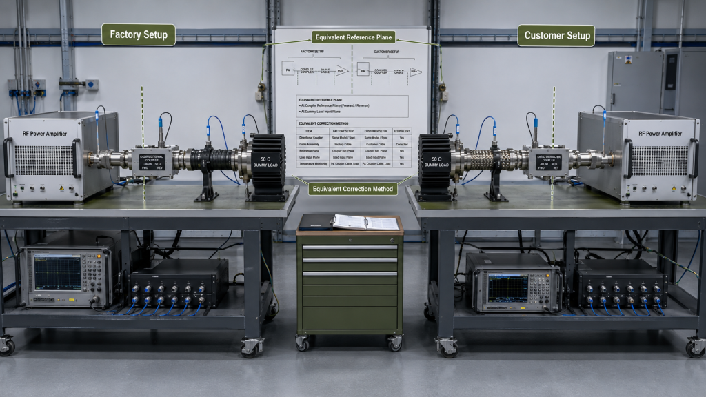
Factory and customer setups do not need the same cable brand. They do need comparable, documented measurement boundaries before their results can be compared.
Compare the documented setup fields below against the same declared test boundary.
| Test item | Factory setup | Customer setup |
|---|---|---|
| Cable model and length | Recorded | Recorded |
| Connector and adapter combination | Recorded | Recorded |
| Return loss | Measured by frequency | Measured by frequency |
| Insertion loss | Measured by frequency | Measured by frequency |
| Power rating | Verified | Verified |
| Coupler location | Defined | Defined |
| Measurement plane | Defined | Defined |
| Correction method | Defined | Defined |
| Dummy-load model and input interface | Recorded | Recorded |
| Frequency and RF power/duty conditions | Recorded | Recorded |
| Bend and support | Recorded | Recorded |
| Ambient and starting temperature | Recorded | Recorded |
| Test duration and hot-state conditions | Recorded | Recorded |
Preserve raw and corrected readings separately.
A difference in final power numbers alone does not identify the cause. Check whether the readings represent the same plane, whether one value is corrected, whether the same correction was applied once, whether the coupler is before or after the cable, and whether temperature, mismatch, load input or operating conditions changed.
Do not attribute the full difference to this jumper when the reference planes or path configuration differ, when a load is included in one measurement but not the other, or when mismatch changes the interpretation. The result may require a condition-matched retest or a separate path investigation.
7. What Evidence Proves Dummy Load Cable Stability?
The record should identify the exact assembly and test condition it supports. The symptom-to-check mapping below helps isolate the next measurement; each possible boundary remains a hypothesis until evidence separates it.
| Observed result | Possible boundary | Correct check |
|---|---|---|
| Coupler-side FWD is stable, but independently measured load-input power is low | Mainline cable loss after the coupler | Compare corrected power at both defined mainline planes. |
| Instrument reading disagrees with an independent power check | Sample cable, attenuator, sensor, calibration, or correction error | Audit the complete low-power measurement chain. |
| REV or VSWR increases | Cable, connector, adapter, coupler, or load mismatch | Perform a low-power S11 check at a defined plane; if an adapter changed, use RF adapter-error checks to separate insertion loss, mismatch and connection repeatability. |
| PA-side REV falls after a longer cable is installed | Cable attenuation may be masking load mismatch | Compare insertion loss, load-input power, temperature, and load-side return loss. |
| Result changes when the cable moves | Termination or mechanical strain | Disable RF and inspect the fixed route. |
| Cold test passes but hot test drifts | Operating power or thermal condition may be outside its applicable limit | Only after prequalification, observe the fixed hot state while readings are stable and within predefined applicable limits. If any condition is unsafe or out of limit, disable RF, allow safe handling, inspect, and requalify before restarting. |
| Connector develops a hotspot | Contact or rating problem | Stop RF, disable drive, reach a safe handling condition, then inspect or replace and requalify before restarting. |
| Factory and customer results differ | Setup, correction, cable identity, or reference plane | Compare the complete test boundaries. |
Include, where required by the project:
- Cable manufacturer, model, assembly ID, length and connector/adapter combination
- PA and dummy-load model or S/N where unit-level traceability applies
- Frequency points, RF power, duty cycle, ambient and cooling conditions, and test duration
- Cable-only S11 setup, far-end matched port or characterized termination, calibration planes and result
- Separate cable-plus-load reflection result when that assembled path is measured
- S21 insertion-loss result by frequency, with cable temperature and correction status
- Applicable power, return-loss, insertion-loss, temperature, reflected-power and VSWR limits from the project or equipment documents
- Coupler location, raw readings, corrected readings, correction basis and represented reference planes
- Final cable support and bend condition, maximum cable/connector temperature, protection status and post-test result where required
- Calibration evidence, setup diagram or photographs and the approved test report when the acceptance plan requires them
A suitable report conclusion is conditional and assembly-specific: “For the identified cable assembly and recorded test configuration, the measurements were within the stated project limits at the listed frequencies, power, duty cycle, reference planes and test duration.” Use that statement only when the supporting records and limits are present. It is not a claim that a particular cable passed here or that the PA, complete system, supplier or every production unit has been approved.
A 50 Ω label, short cable, continuity result, tightened connector or visually stable power reading alone does not establish cable qualification.
What Dummy Load Cable Requirements Should Be Defined Before RFQ?
Define the acceptance boundary before the cable is selected or a high-power test is scheduled. Specify these inputs in the RFQ:
| RFQ item | Why it matters |
|---|---|
| Required frequency range and test points | Establishes the frequencies at which the assembly and its evidence must apply. |
| Cable specification, assembly identity, and evidence for a proposed assembly | Prevents use of an unidentified or under-rated jumper. |
| Maximum cable length, where applicable | Keeps the proposed route within the length assumed by the loss, support, and operating-condition evidence. |
| Connector and adapter combination | Defines the assembled RF path whose mismatch, rating, and test results are being qualified. |
| Dummy-load input interface | Confirms the cable end matches the specified load connection and mechanical interface. |
| Average/CW power, peak power where relevant, duty cycle, cooling, and duration | Defines the operating conditions needed to assess heating and rating suitability. |
| Cable-only return-loss method and far-end termination; separate cable-plus-load reflection measurement where needed | Distinguishes the cable measurement from the combined cable-and-load result. |
| Maximum insertion loss by frequency and measurement planes | Controls RF power lost before the dummy load and identifies where that loss is measured. |
| Coupler position; raw and corrected values; correction method and owner | Separates PA-plane from load-input power and prevents missing or double compensation. |
| Bend radius, support, connector-exit, access, and maintenance space | Prevents connector loading and route changes from invalidating the test boundary. |
| Applicable return-loss, power, temperature, reflected-power, and VSWR limits with their source | Makes acceptance conditions traceable to applicable project or equipment documents without inventing universal limits. |
| Ambient-temperature range | Defines the environmental condition under which equipment ratings and thermal results apply; specify the applicable project range. |
| Hot-state duration and output-drift condition | Defines the thermal observation period and the drift boundary to be assessed. |
| Protection-response boundary | Defines the required response and safe stop condition for the stated setup. |
| Repeat-installation requirement and post-maintenance retest conditions | Defines when reinstallation or maintenance requires a repeat qualification under the specified conditions. |
| Calibration, traceability, and report format | Makes the measurements auditable and factory/customer retests comparable. |
| Responsibility for cable selection, qualification, maintenance, and replacement | Identifies who owns each decision and lifecycle action. |
Use project limits and evidence for the actual assembly; generic wattage multipliers or assumed universal RF thresholds are not substitutes. The responsible project authority should identify who reviews the evidence and who approves the test before RFQ or acceptance.
Conclusion
Qualify the identified dummy-load jumper against its stated frequency, power/duty, connector, support, thermal and measurement-plane conditions. Separate cable-only S11 from a cable-plus-load reflection result, and do not treat a lower PA-side REV as proof that the load improved.
If identity, applicable limits, measurement setup or safe condition is unresolved, hold the test until the evidence is complete. Before RFQ, define the required cable assembly and test-acceptance records. For module-family discovery after setting the test boundary, review RF power amplifier modules; a family listing does not establish that a specific amplifier suits this cable or test path. For RFQ preparation, contact RF SKYPOWER with the cable identity and test-acceptance inputs defined above.