


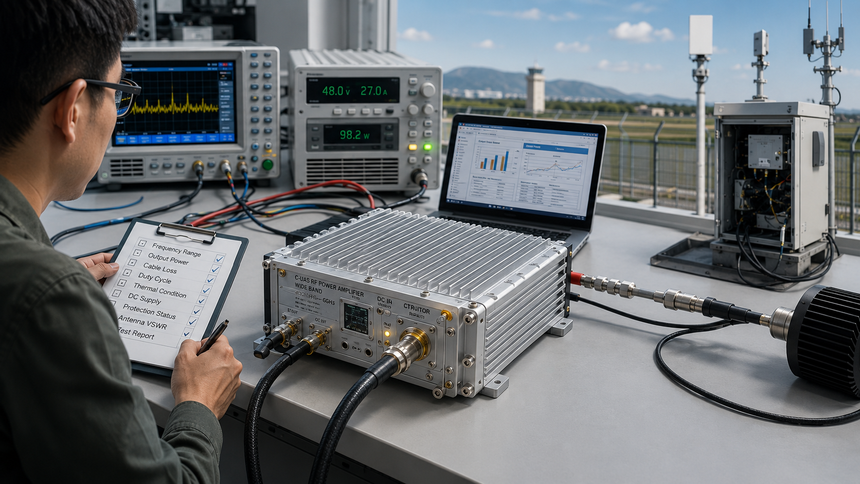
Choosing RF Power Amplifier power margin requires more than matching the target wattage, because real usable output is reduced by cable loss, connector loss, antenna mismatch, thermal derating, duty cycle, DC supply limits, and full-band variation. Even a module rated at 100W under controlled bench conditions may deliver less usable power once it is installed in a multi-channel C-UAS RF chain.
For system integrators, the real question is not only “Can this module reach the target wattage once?” The better question is whether RF Power Amplifier power margin is enough to keep the system stable after field losses and derating are included. In C-UAS projects, power margin affects suppression consistency, retest confidence, thermal stability, and long-term reliability. It is not wasted capacity. It is the engineering room that keeps the RF chain from operating at the edge of failure.
1. Why Is RF Power Amplifier Power Margin Not Optional?
RF Power Amplifier Power Margin is not optional because the module rarely works under the same clean conditions used for a short factory output test. In real deployment, you must account for cable length, RF transitions, antenna load, cabinet heat, power supply behavior, and operating time before deciding whether the selected wattage is truly enough.
Here’s the engineering point: power margin is not the same as blindly choosing a larger amplifier. It is the difference between the required usable RF output and the sustainable output that remains after field variables are included.
What Does Power Margin Really Mean?
Power margin means the RF chain has enough reserve capacity to maintain target performance without forcing the amplifier to work at its maximum limit all the time. You can think of it as engineering space across multiple areas:
- RF output margin after cable and connector loss
- Thermal margin under high ambient temperature
- DC supply margin under full load
- Load margin when VSWR is not ideal
- Frequency margin across the required operating band
If your project only checks the rated output number, you may approve a module that looks correct on paper but has little field tolerance.
Key Takeaway: Power margin helps you judge whether the RF amplifier can support the system under real operating conditions, not only under ideal test conditions.
| Margin Area | What It Protects | Why It Matters |
|---|---|---|
| RF output margin | Usable antenna-side power | Prevents field power shortage |
| Thermal margin | Long-duty stability | Reduces derating risk |
| DC supply margin | Voltage and current support | Prevents output drops |
| Load margin | VSWR tolerance | Reduces protection stress |
This table shows why power margin is a system-level requirement, not just a wattage number.
2. How to Avoid RF Power Amplifier Wattage Mismatch
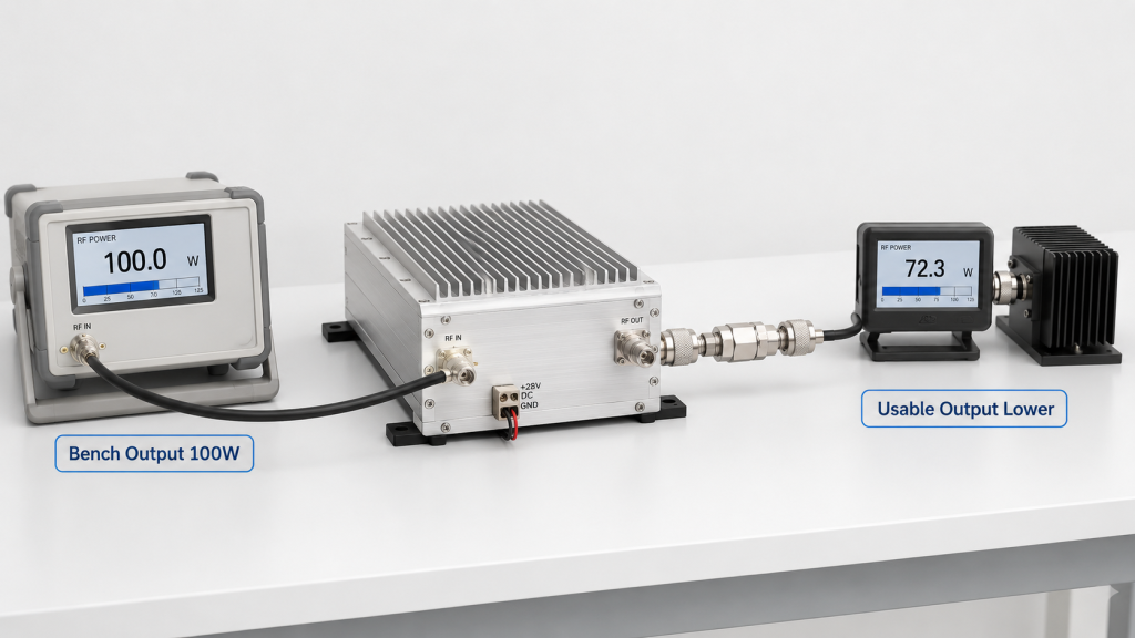
When target wattage is matched too closely, RF Power Amplifier Power Margin disappears before the system reaches the real antenna load. A 100W requirement does not automatically mean a 100W module will provide stable 100W usable output after installation.
The practical risk is clear: every small loss becomes important when there is no reserve. A cable loss, a slightly poor connector, a warm cabinet, or a less-than-perfect antenna match can turn an approved module into an underpowered system.
Where Does a Tight Selection Fail First?
A tight power selection usually fails in the areas that were not included in the early RFQ. These areas may look secondary during procurement but become visible during commissioning:
- Lower antenna-side output than expected
- More frequent thermal protection
- Different customer retest results
- Less tuning room during integration
- Higher sensitivity to batch tolerance
You do not need to assume that every close-match design will fail. The point is that it carries less tolerance for normal field variation.
Key Takeaway: Matching wattage too closely may reduce initial cost, but it also reduces your ability to absorb real RF chain loss and environmental derating.
| Close-Match Risk | Field Result | Engineering Impact |
|---|---|---|
| Cable loss ignored | Antenna-side power drops | Coverage may shrink |
| Heat ignored | Output derates | Long-duty stability weakens |
| Load mismatch ignored | VSWR alarms increase | Protection activates often |
| Retest setup differs | Disputes appear | Acceptance becomes harder |
This table helps buyers understand why a passing factory test may not equal a passing field system.
3. What Causes RF Power Amplifier Margin Loss in the RF Chain
Cable, connector, and antenna loss consume RF Power Amplifier Power Margin because output power must travel through the complete RF path before it becomes useful at the load. The amplifier output port is only the starting point, not the final delivered point.
This is where system integrators should pay attention: a clean module test can hide system-level loss. Long cables, extra adapters, bent cable paths, poor connector contact, and antenna mismatch all reduce or disturb usable RF output.
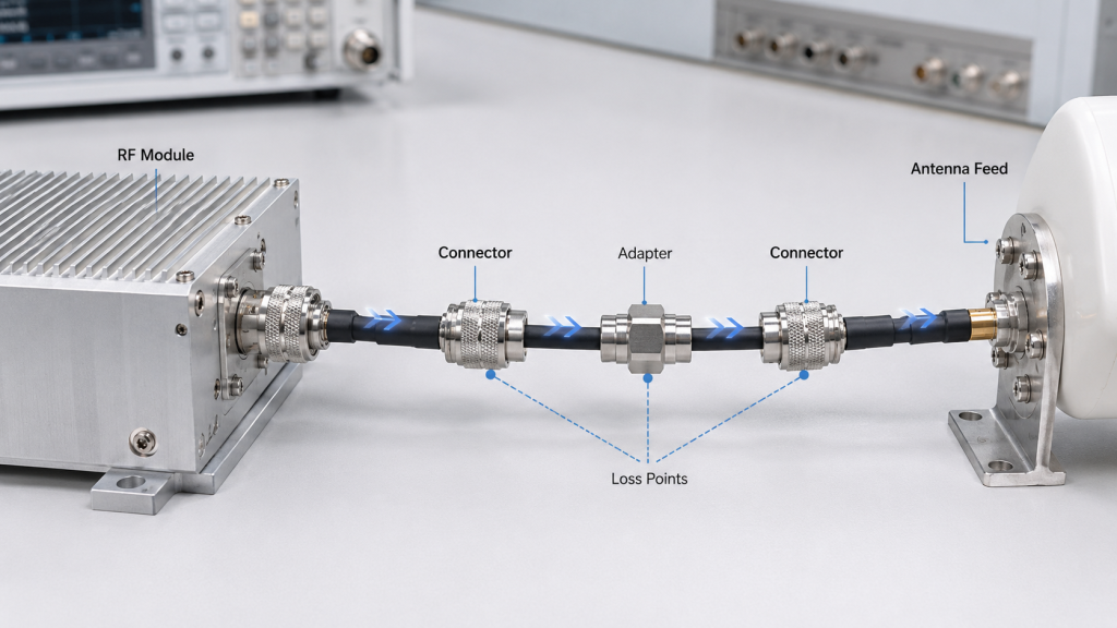
What Should Be Included in the RF Chain Budget?
An RF chain budget does not need to be complicated at the first review stage, but it should include the major loss points. You should at least check:
- Cable type, cable length, and frequency-related loss
- Connector quantity and contact quality
- Adapter count and impedance consistency
- Antenna feed condition and VSWR
- Bend stress or compression in the RF cable path
In wideband C-UAS systems, the same cable path may behave differently across frequency bands. Higher frequencies often make cable quality and connector repeatability more visible.
Key Takeaway: RF chain loss turns module-rated output into system-usable output, so power margin must cover the path between the amplifier and the real load.
| RF Path Element | How It Affects Margin | What to Review |
|---|---|---|
| Cable | Insertion loss | Length, grade, frequency |
| Connector | Contact loss | Torque, plating, fit |
| Adapter | Extra transition loss | Quantity and quality |
| Antenna feed | Reflected power | VSWR and installation |
| Cable bend | Local path disturbance | Bend radius and stress |
This table gives you a practical starting point before approving the amplifier wattage.
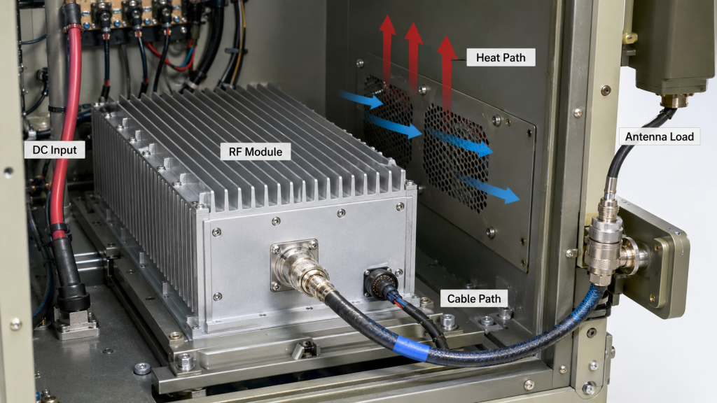
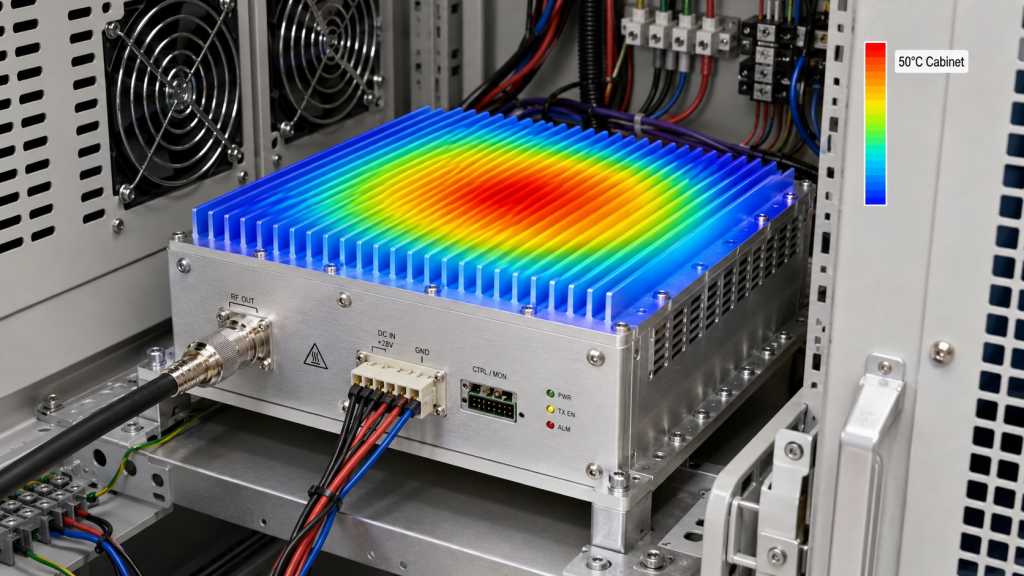
4. How to Account for Thermal Derating in RF Power Amplifier Selection
Thermal derating changes real output power because RF Power Amplifier Power Margin must be judged at the hottest expected operating condition, not only at room temperature. A module may reach rated output at 25°C but reduce output when cabinet heat, sunlight, duty cycle, or airflow limits increase internal temperature.
Here’s the field reality: derating is not automatically a quality problem. It is often a protection response that prevents device damage when thermal stress becomes too high.
What Thermal Conditions Should You Confirm?
Before approval, you should connect the power decision to the expected thermal condition. The useful questions are specific:
- What ambient temperature will the system face?
- Is the module inside a closed cabinet?
- Is airflow close to the factory test condition?
- Will multiple RF modules run at the same time?
- Is the duty cycle continuous, intermittent, or trigger-based?
A larger amplifier can still fail if the thermal path is weak. Power margin and thermal design must be reviewed together.
Key Takeaway: Thermal derating converts datasheet wattage into real operating wattage, so your selected margin must survive the hottest credible condition.
| Thermal Variable | Effect on Output | Selection Question |
|---|---|---|
| Ambient heat | Reduces safe operating room | What is the worst temperature? |
| Cabinet airflow | Controls heat removal | Is airflow restricted? |
| Duty cycle | Raises average heat | How long is output active? |
| Multi-module heat | Adds thermal load | Are channels simultaneous? |
This table shows why thermal review belongs in power selection, not only in mechanical design.
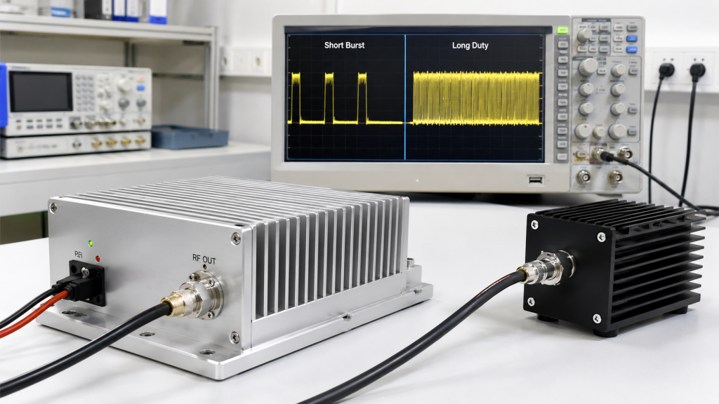
5. What Is the Impact of Duty Cycle on RF Power Amplifier Output
Duty cycle affects RF Power Amplifier Power Margin because short peak output and long-duty output create very different thermal, electrical, and reliability demands. The same 100W number can mean very different things depending on how long the amplifier must transmit.
Here’s the engineering point: you should not approve power only by peak wattage. You should ask whether that output is required for seconds, minutes, hours, or continuous operation.
What Duty-Cycle Details Should Be Stated?
A useful RFQ should describe the operating mode, not only the power number. You should define:
- Continuous wave or intermittent output
- Trigger-based or scheduled operation
- Single-band or multi-band simultaneous output
- Expected active time during an event
- Required recovery behavior after high-load operation
For C-UAS systems, duty cycle may change during a real incident. A system that normally works at a low duty cycle may face longer active periods during multi-target events.
Key Takeaway: Duty cycle tells you whether the amplifier is being selected for a short output event or a sustained field mission.
| Duty-Cycle Condition | Power Selection Risk | What You Should Ask |
|---|---|---|
| Short burst | Peak rating may be enough | How long is each burst? |
| Intermittent output | Heat accumulates slowly | What is the repeat cycle? |
| Long-duty output | Thermal stress rises | Can output be sustained? |
| Multi-band output | Heat stacks across modules | Are channels simultaneous? |
This table helps separate peak power approval from real operating approval.
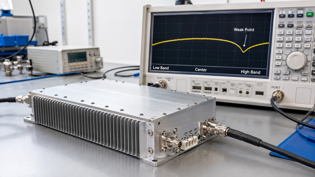
6. Why Do Frequency Range and Gain Flatness Affect Margin?
Frequency range and gain flatness affect RF Power Amplifier Power Margin because one strong frequency point does not prove enough usable output across the full band. A wideband module may show different gain, efficiency, heat, and output behavior at different frequencies.
This is where full-band evidence matters. Before defining margin, engineers should start by choosing the correct RF Power Amplifier frequency range and then checking whether output remains usable across that range.
What Should Be Checked Across the Band?
The power margin decision should look at the weakest relevant points, not only the best point. Review the following:
- Output power at low, center, and high band points
- Gain flatness and gain ripple
- Band-edge output behavior
- Efficiency variation across frequency
- Thermal behavior at difficult frequency points
This does not mean wideband modules are weaker than narrowband modules. It means wideband claims need full-band proof.
Key Takeaway: Power margin must be checked across the required operating band because the system fails at its weak points, not at its strongest test point.
| Full-Band Factor | What It Reveals | Why It Affects Margin |
|---|---|---|
| Output flatness | Power consistency | Finds weak output zones |
| Gain flatness | Amplification consistency | Predicts tuning difficulty |
| Band-edge behavior | Edge performance | Prevents false confidence |
| Efficiency variation | Heat difference | Affects derating risk |
This table gives buyers a simple way to connect full-band data with power selection.
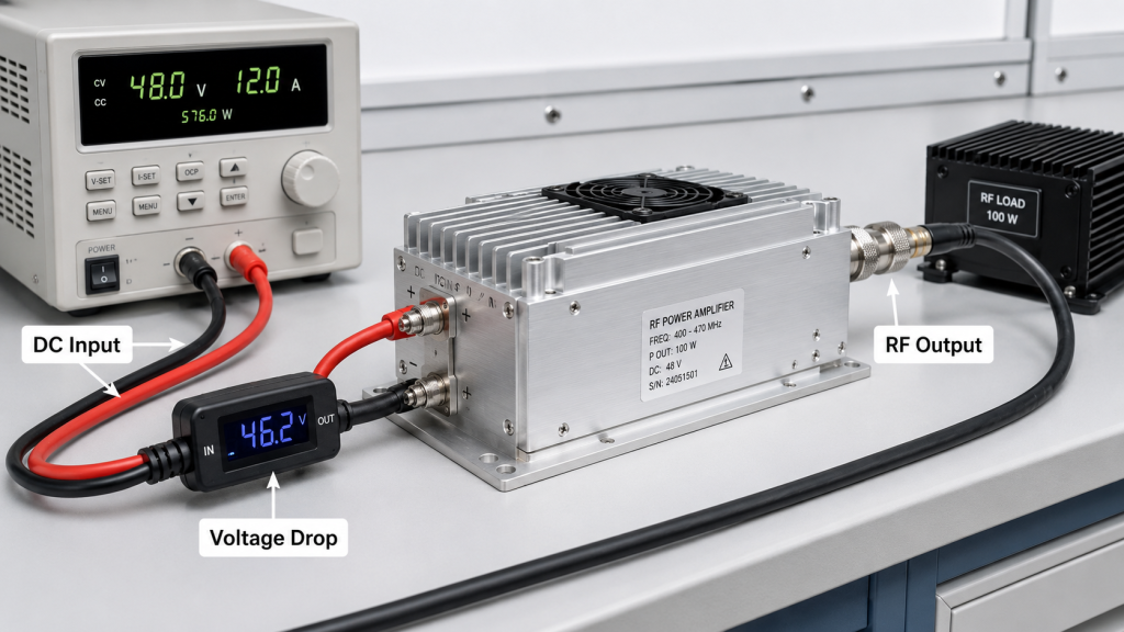
7. How to Ensure DC Power Supports RF Power Amplifier Margin
Power supply limits reduce RF Power Amplifier Power Margin because RF output depends on stable DC voltage, current capacity, and transient response under load. If the DC side cannot support the RF demand, the amplifier cannot maintain the selected output reliably.
The practical risk is clear: the RF module may be blamed for weak output when the real limitation is voltage drop, undersized wiring, weak power supply capacity, or poor multi-module power planning.
What DC Conditions Should Be Reviewed?
You should confirm the DC system as part of the RF power approval. The review should include:
- Module-side voltage under full RF load
- Current capacity with safety margin
- DC cable length and voltage drop
- Ripple and transient behavior
- Startup sequence for multi-module systems
If you need a deeper power-side review, use a dedicated guide on how to power RF Power Amplifiers without output drops before final cabinet wiring.
Key Takeaway: RF power margin only works when the DC power system can deliver the voltage and current needed under real load.
| DC Factor | Possible Problem | Field Symptom |
|---|---|---|
| Voltage drop | Lower module-side voltage | Output power falls |
| Low current capacity | Supply stress | Shutdown or instability |
| Ripple | RF chain disturbance | Noise or control issues |
| Weak transient response | Slow load support | Output dips during events |
This table shows why RF output approval must include DC input verification.
8. Why Do Protection Circuits Need Margin, Not Constant Stress?
Protection circuits need margin because RF Power Amplifier Power Margin should prevent constant thermal, voltage, and load stress rather than relying on alarms to rescue a tight design. VSWR, temperature, and voltage protection are safety mechanisms, not substitutes for proper selection.
Here’s the field reality: if protection activates often, the question should not only be whether the protection threshold is sensitive. You should check whether the RF chain has enough margin for heat, load, power supply, and duty cycle.
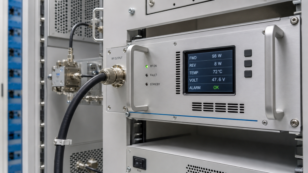
What Protection Signals Should Be Treated as Engineering Data?
Protection status can help integrators find where margin is being consumed. Useful signals include:
- Forward power feedback
- Reflected power or VSWR alarm
- Temperature alarm or thermal derating
- Voltage alarm
- Current status
- Enable and fault recovery status
A professional RF module should make these conditions visible enough for the system controller to react. But visibility does not remove the need for margin.
Key Takeaway: Protection circuits protect hardware from abnormal conditions, while power margin reduces the chance that normal operation constantly becomes abnormal.
| Protection Type | What It Indicates | What to Check First |
|---|---|---|
| VSWR protection | Load mismatch | Antenna, cable, connector |
| Temperature protection | Heat stress | Airflow, duty cycle, heatsink |
| Voltage protection | DC instability | Supply, cable, bus voltage |
| Current alarm | Load or supply stress | Operating mode and wiring |
This table helps your team treat alarms as diagnostic evidence rather than isolated faults.
9. How Should Power Margin Be Defined for C-UAS Scenarios?
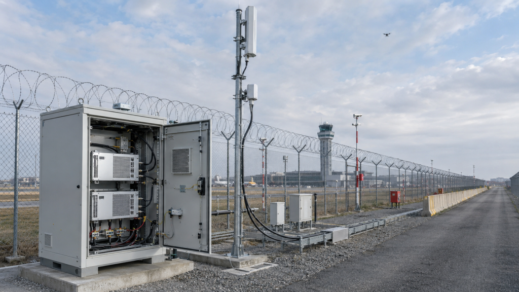
RF Power Amplifier Power Margin should be defined by the real C-UAS scenario because different platforms create different RF, thermal, power, and maintenance constraints. A vehicle-mounted system, fixed station, airport perimeter, remote border site, and critical infrastructure cabinet cannot all use the same margin logic.
This is where system context matters. In low-altitude security and C-UAS system integration, you should define margin from the target operating condition backward, not from a clean module label forward.
Which Scenario Variables Change the Margin?
You should review scenario variables before confirming wattage. Typical examples include:
- Vehicle vibration and DC bus fluctuation
- Fixed-site long-duty operation
- Airport perimeter reliability requirements
- Remote site maintenance limits
- Multi-band thermal stacking
- Long antenna feed paths
For example, an airport counter-UAS RF deployment may require stable output, controlled RF behavior, and predictable long-duty operation under perimeter conditions. That is a different approval logic from a short bench demonstration.
Key Takeaway: Power margin should be sized for the deployment scenario, not copied from a generic wattage table.
| Scenario | Main Margin Concern | Review Priority |
|---|---|---|
| Vehicle-mounted C-UAS | Vibration and DC fluctuation | Wiring and thermal path |
| Fixed station | Long-duty heat | Derating and airflow |
| Airport perimeter | Predictable operation | Validation and control |
| Remote site | Maintenance difficulty | Reliability and supply margin |
| Multi-band system | Heat stacking | Channel-level budgeting |
This table helps you connect the operating environment to the power selection method.
10. How to Define RF Power Amplifier Power Margin Before Approval
You should choose RF Power Amplifier Power Margin before approval by matching target output, full-band behavior, RF chain loss, duty cycle, thermal limits, DC supply, and protection status. The approval process should start with the field requirement, not the catalog wattage.
Here’s the engineering point: a better RFQ does not say only “100W module.” It states the frequency band, target usable output point, duty cycle, cable path, antenna condition, thermal environment, DC supply, and expected validation method.
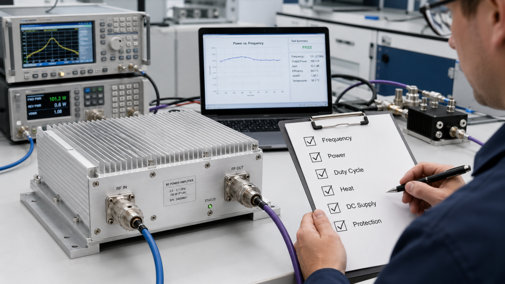
What Should Be in the Approval Checklist?
A useful approval checklist should let engineering, procurement, and the supplier review the same operating assumptions. Include:
- Required usable output point
- Frequency band and worst frequency points
- RF chain loss estimate
- Duty cycle and operating time
- Ambient temperature and cooling condition
- DC voltage and current support
- VSWR, temperature, and voltage protection visibility
- Factory test report conditions
As an RF Power Amplifier module and C-UAS core component source factory, RF SKYPOWER can support this discussion by reviewing frequency band, target output, duty cycle, cable loss, thermal condition, DC supply, protection status, and test evidence before final approval.
Key Takeaway: The best time to define power margin is before procurement approval, when RF, thermal, DC, and field conditions can still be aligned.
| Approval Item | Why It Matters | Evidence to Request |
|---|---|---|
| Target usable output | Defines the real requirement | Output point definition |
| Full-band behavior | Finds weak frequency zones | Sweep or multi-point data |
| RF chain loss | Converts module power to load power | Cable and connector review |
| Duty cycle | Sets heat demand | Operating mode statement |
| DC supply | Supports RF conversion | Voltage/current test data |
| Protection status | Shows operating stress | Alarm and feedback data |
This table can be copied into early RFQ or technical confirmation documents.
FAQ
Can I choose a 100W RF Power Amplifier for a 100W target?
Not safely in many real systems. You should first confirm whether the 100W target is required at the module output, cable end, antenna port, or another system reference point.
What’s the best power margin for a C-UAS RF chain?
There is no universal percentage. The best margin depends on cable loss, frequency range, antenna match, duty cycle, thermal condition, DC supply, and the required usable output point.
How do I know if my power margin is too low?
Your margin may be too low if field output drops below target, thermal derating appears quickly, VSWR alarms are frequent, or small installation changes cause large performance differences.
Can protection circuits replace power margin?
No. Protection circuits prevent damage during abnormal stress, but they cannot make a tightly selected RF chain stable under poor heat, weak supply, or mismatched load conditions.
What’s the best test evidence before approval?
The best evidence is test data that states frequency points, output power, input drive, DC voltage, load condition, temperature, duty cycle, test duration, and the RF path used during measurement.
Conclusion
RF Power Amplifier selection should not begin and end with target wattage. This article explained why power margin is affected by cable and connector loss, antenna load, thermal derating, duty cycle, frequency variation, DC supply limits, protection behavior, and real C-UAS deployment conditions. A module that matches the required number on paper may still fall short if the system has no room for field loss or derating.
For system integrators and technical buyers, the practical goal is clear: define the required usable output first, then work backward through the RF chain, thermal condition, DC supply, duty cycle, and validation evidence. RF SKYPOWER can help review RF Power Amplifier power margin before final approval for vehicle-mounted, fixed-site, airport, border, and critical infrastructure C-UAS projects. If your team needs engineering support before selecting the final module power level, contact us today.
Reliable C-UAS performance is not built by chasing the largest wattage label; it is built by engineering verified RF power that remains usable under real field conditions.