










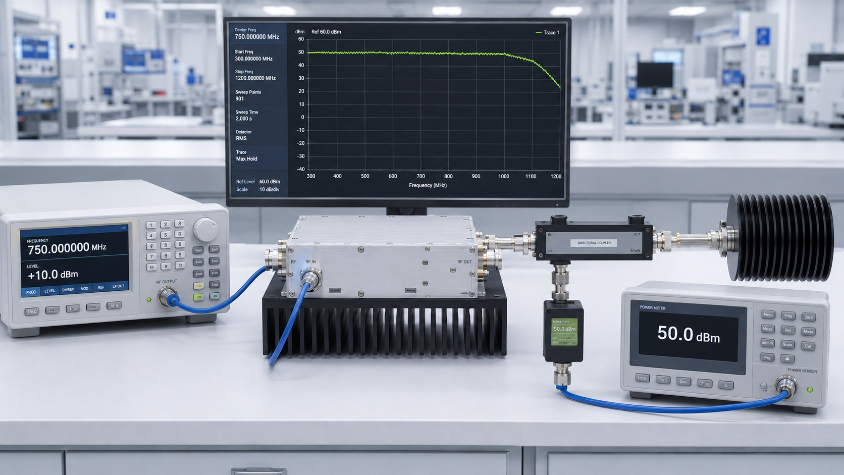
Band edge performance can reveal RF PA problems that a clean center-frequency result hides. A module may reach its target output in the middle of the band but produce less power, require more drive, run hotter, or trigger protection near a required low or high frequency.
The central conflict is simple: center-frequency data shows the PA at one favorable point, while project acceptance must prove that every required edge and critical channel remains usable under the same input, load, voltage, cooling, and hot-state conditions.
A low/center/high screenshot can support an early review. It should not be treated as complete full-band evidence.
1. Which Band Edges Actually Matter to the Project?
The frequencies that matter are not always the lowest and highest numbers printed on the datasheet.
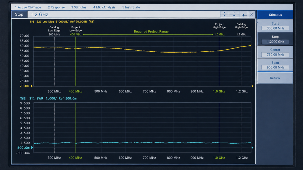
A project may need to distinguish:
- Catalog low and high edges
- Actual project low and high edges
- Critical operating channels
- Filter or switch transition points
- Overlap points between adjacent RF modules
- Frequencies that showed weak output in earlier tests
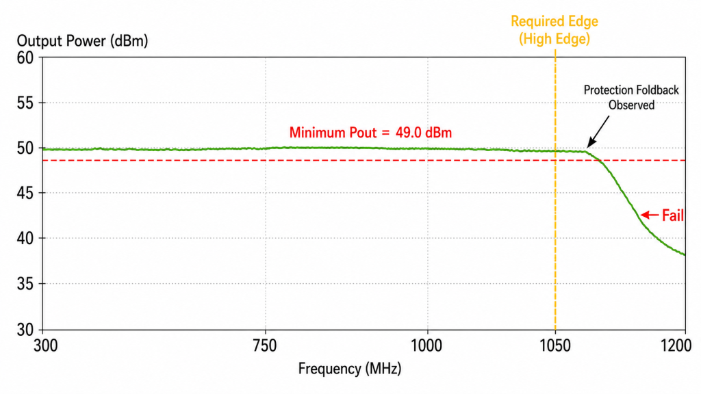
For example, a PA may be rated from 300 to 1200 MHz while the project only requires 400 to 1000 MHz. The project acceptance boundary should focus first on 400 MHz, 1000 MHz, and any critical channels inside that range.
Catalog endpoints may still be tested for product characterization, but they should not automatically replace project-defined pass/fail points.
This is why RF PA frequency range selection should be completed before the band-edge test plan is locked.
The RFQ should clearly separate:
- Required pass/fail frequencies
- Informational characterization points
- Out-of-band observations
Testing outside the required range does not silently extend the guaranteed operating band.
2. Why Can Center or Three-Point Data Miss a Real Failure?
A center-frequency test confirms that the setup works at one point. A low/center/high test provides a useful screen. Neither proves that the complete required band is stable.
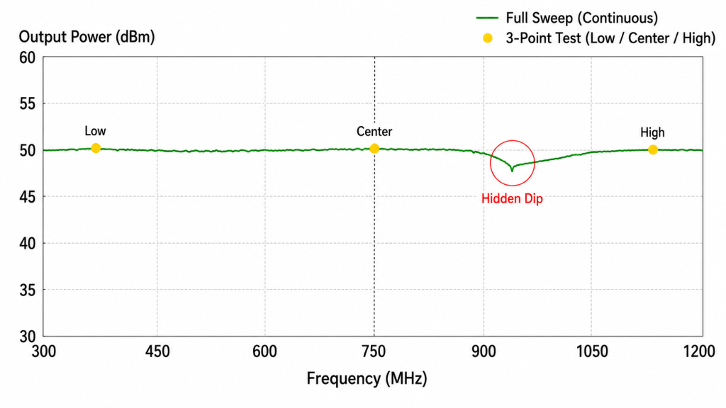
Three-point data can miss:
- A narrow output dip
- Local gain ripple
- Matching-network transitions
- Filter roll-off
- A weak project channel between test points
- Frequency-sensitive compression
- A protection event in a small frequency region
The test plan should therefore define either an exact frequency list or a maximum sweep step. Denser points should be added near rapid changes, required channel edges, filter transitions, or previously weak regions.
Temperature can also distort the result.
If the sequence is:
Low edge → Center → High edge
the high-edge result may look worse partly because the module is hotter when that point is tested. The difference may contain both a frequency effect and a thermal effect.
A practical method is:
- Run a broad cold-state sweep.
- Identify the weakest frequencies.
- Repeat the required edges with controlled dwell.
- Record case, heatsink, and ambient temperature.
- Repeat selected points after thermal stabilization.
- Use a reverse-order sweep when test-order bias is possible.
The goal is not to hold every frequency for the same long duration. The broad sweep finds risk, while focused hot-state tests prove the required edges and critical channels.
3. How Should Pin, Pout, and Gain Be Controlled?
A constant signal-generator setting does not guarantee constant RF power at the PA input.
Input cables, attenuators, switches, filters, and driver stages can all change the actual Pin with frequency. If Pin varies during the sweep, the resulting Pout curve cannot be attributed only to the PA.
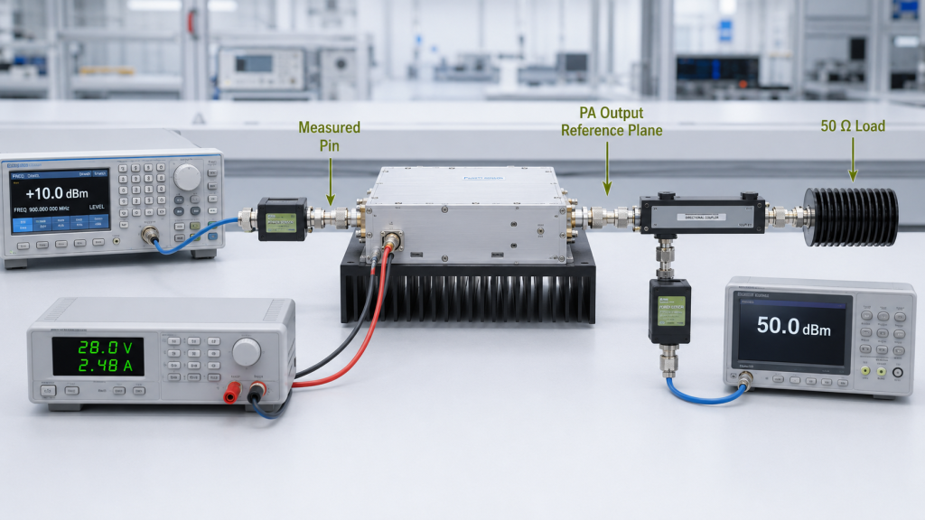
The test should record:
- Source setting
- Actual Pin at the PA input
- Pout at the defined output plane
- Gain
- Drive adjustments
- Module-terminal voltage
- Load condition
Two test modes are commonly useful.
Constant measured Pin is suitable for comparing how gain, Pout, current, and temperature change with frequency.
Adjusted Pin to target Pout is suitable for checking whether every required frequency can reach the target output and how much drive it needs.
The selected mode must be stated in the report. If Pin changes at every frequency, the resulting curve should not be presented as a constant-input gain-flatness test.
Gain and output power must also remain separate.
Gain = Pout − Pin
A smooth gain curve does not prove that full-power Pout is stable. Output may also change because of compression, load mismatch, voltage, temperature, protection foldback, or signal-linearity requirements.
Detailed gain behavior belongs in the RF PA gain-flatness check. Band-edge approval should use gain as one part of the evidence, not as a replacement for actual output data.
The output reference plane must remain consistent. Do not compare low-edge power at the PA connector with high-edge power after a feeder or filter.
For RF Power Amplifier Modules, the test boundary should state which cables, couplers, filters, switches, and adapters are included and which losses are corrected. The method should remain consistent with the swept-frequency full-power RF PA test.
4. What Makes a Band-Edge Result Pass or Fail?
The main pass/fail question is not:
How many dB below the center frequency is the edge?
The better question is:
Does every required frequency still meet its absolute minimum compliant output under the defined operating condition?
An edge may be 1 dB below the center and still pass if enough usable output remains. Another point may be only 0.3 dB lower but fail because it falls below the project requirement.
The acceptance limit should define, by frequency:
- Minimum compliant Pout
- Pin-control rule
- Output reference plane
- Signal type
- Duty cycle and dwell time
- Module-terminal voltage
- Load or VSWR condition
- Thermal condition
For modulated signals, maximum wattage is not enough. The output must still meet the required EVM, ACLR, spectral mask, or distortion limit.
Protection behavior must also be interpreted correctly. If the PA reduces output, alarms, or shuts down at a required edge, the protection system may be working as designed. That does not prove the original output requirement passed.
Record:
- Output before protection
- Output after protection
- FWD and REV
- VSWR
- Alarm or shutdown condition
- Recovery behavior
The weakest verified frequency should then be used in the RF PA power-margin calculation. Margin should not be calculated from the best center-frequency result.
5. What Evidence Is Strong Enough for Approval?
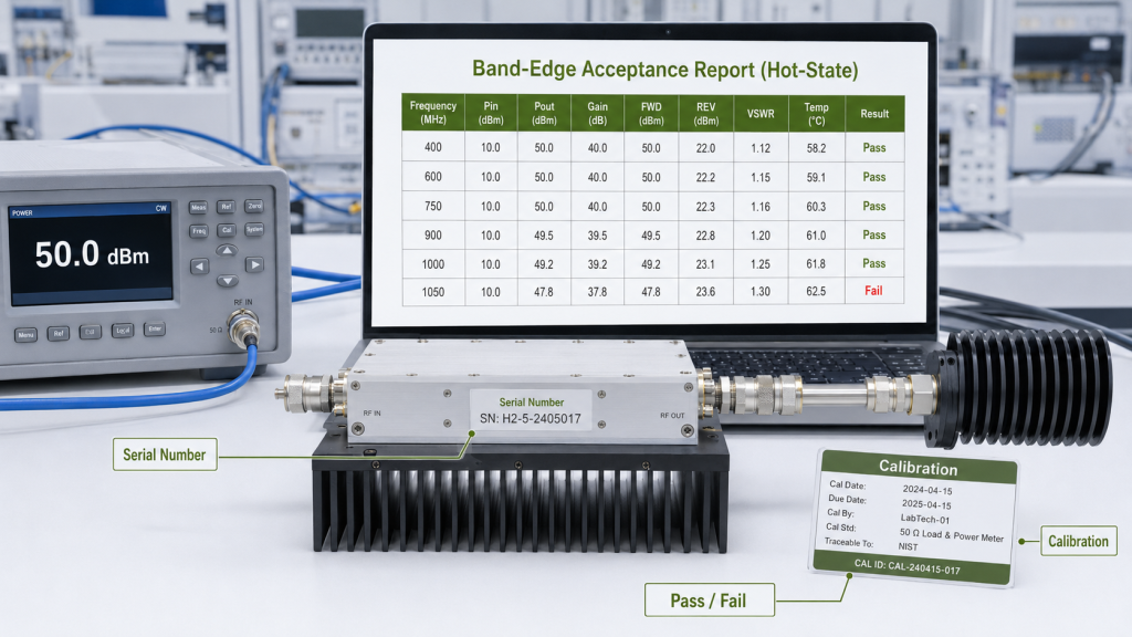
A smooth graph or three screenshots are not enough to approve band-edge performance.
| Weak evidence | Better acceptance evidence |
|---|---|
| Center-frequency output only | Required edge and critical-channel results |
| Low/center/high screenshots | Defined sweep point list and maximum step |
| Gain curve without Pin | Actual Pin, Pout, and gain by frequency |
| Pout without reference plane | Defined PA-port or system output plane |
| Cold sweep only | Cold sweep plus hot-state critical-point tests |
| Protection did not trip | Output, REV, VSWR, alarm, and recovery data |
| Generic model report | Report linked to the delivered unit’s S/N |
The final evidence package should include:
- PA model and serial number
- Exact test frequencies
- Pin, Pout, and gain by frequency
- Output reference plane
- Module-terminal voltage
- Duty cycle and dwell time
- Thermal records
- FWD, REV, and VSWR
- Cold and hot results
- Calibration and correction data
- Pass/fail status at each required point
This evidence should prove the exact delivered unit under the agreed test boundary.
What Band-Edge Information Should Be Defined Before RFQ?
| RFQ item | Customer input needed | What it confirms |
|---|---|---|
| Required frequency range | Actual low and high operating frequencies | Defines the project edges |
| Critical channels | Exact frequencies that must pass | Prevents important points from being missed |
| Sweep plan | Frequency list or maximum step | Defines test resolution |
| Pin-control rule | Constant Pin or adjusted drive | Makes frequency comparisons valid |
| Required Pout | Minimum output by frequency | Creates the main pass/fail boundary |
| Output reference plane | PA port, cabinet output, or another plane | Defines where power is measured |
| Signal type | CW or modulation details | Defines compliant output |
| Thermal condition | Ambient, cooling, duty, and duration | Defines hot-state performance |
| Load boundary | Dummy load, VSWR, or installed path | Defines the RF load condition |
| Protection requirement | Alarm, foldback, shutdown, and recovery limits | Defines acceptable protection behavior |
| Report requirement | Raw data, calibration, and S/N linkage | Makes the evidence reviewable |
Conclusion
Band edge performance should not be approved from center-frequency data or a basic three-point screen.
The correct decision uses project-defined edge frequencies, controlled Pin, one measurement plane, absolute minimum output limits, hot-state checks, load data, and S/N-linked evidence.
Send our RF engineering team your required frequency range, critical channels, Pin-control rule, minimum Pout by frequency, duty cycle, cooling condition, load boundary, and report requirements.
RF SKYPOWER will review the band-edge test boundary and required evidence before the final RF PA frequency range is approved.