










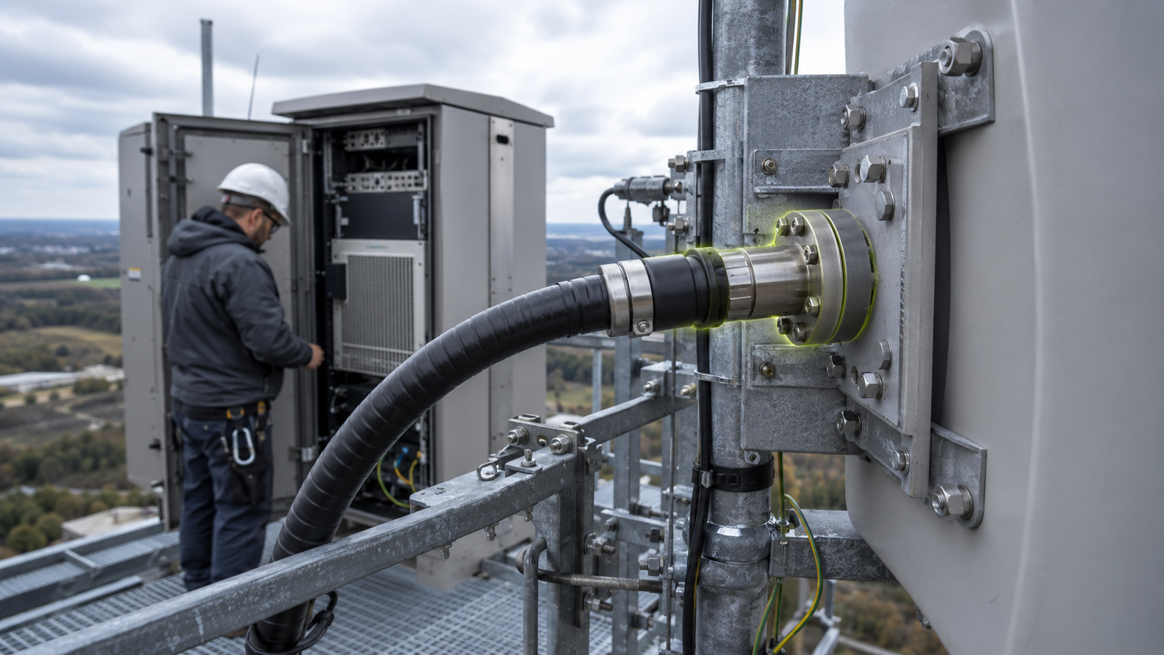
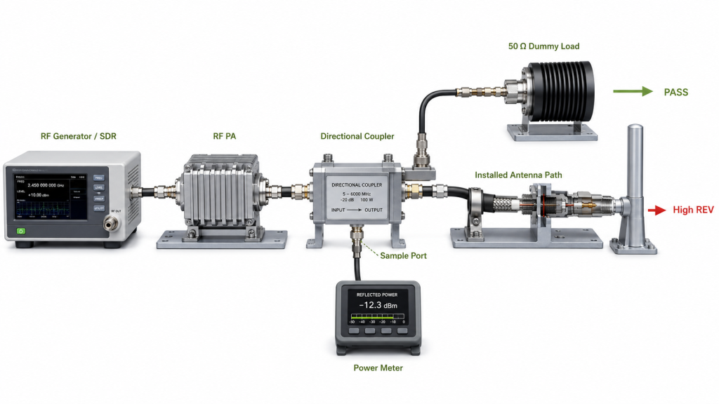
An RF PA can pass a controlled 50 Ω dummy-load test and still show higher reflected power, unstable VSWR, or intermittent alarms after the antenna-side connection is installed. That does not prove the amplifier is faulty. The problem may be local to the antenna feed interface: the mating connector, bulkhead, feed transition, adapter, contact surfaces, or mechanical support immediately around that connection.
Check that interface as its own RF boundary. Define the physical mating point and measurement plane, inspect contact geometry and seating, reproduce the result without changing several other parts, and repeat the check after the final assembly is mechanically supported and thermally stable.
A feed-interface check does not replace full installed-path acceptance. The broader comparison between the controlled PA baseline and the complete feeder-and-antenna chain belongs in dummy-load testing versus real antenna checks.
What an RF PA Antenna Feed Interface Includes—and Excludes
For this check, the antenna feed interface is the accessible RF connection between the feeder path and the antenna input. Depending on the installation, it may include:
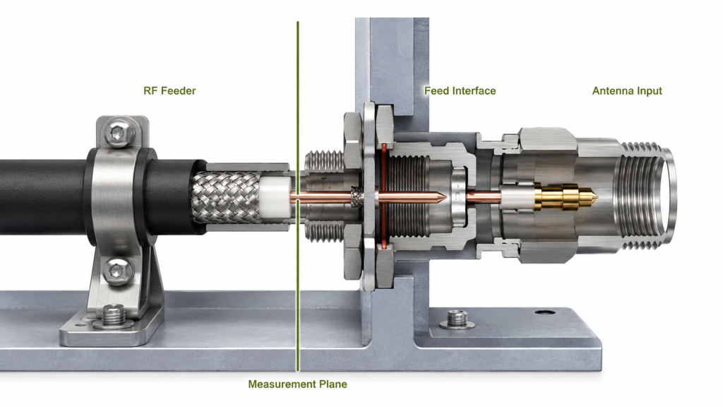
- the antenna input connector;
- a panel or bulkhead connector;
- a coaxial feed transition;
- a replaceable mating adapter;
- a weather-exposed feed point;
- the mechanical support that keeps the mating interface aligned.
Keep the diagnosis at that physical connection. The antenna’s internal matching network, the full feeder-loss budget, a cable crimp hidden behind the termination, and the complete installed antenna path need separate checks.
A stable interface needs more than electrical continuity. It must maintain:
- compatible connector geometry;
- stable center-contact alignment and mating depth;
- reliable outer-conductor contact;
- intact dielectric and plating;
- repeatable mechanical seating;
- cable support that does not side-load the connector;
- repeatable RF behavior after remating and warm-up.
A local defect can change impedance, contact resistance, current distribution, or mechanical stability. The observed result may be higher REV power, poorer return loss, VSWR drift, local heating, frequency-sensitive behavior, or an alarm. Those symptoms tell you where to investigate next, but not which part has failed.
How to Tell an Interface Fault From Cable, Antenna, or Whole-Path Problems
Start with the last controlled condition that is already known. If the PA cannot reproduce its approved baseline into a suitable 50 Ω load under the required operating condition, adding the antenna feed interface will not isolate the fault.
Once the controlled PA baseline is available, compare only the boundaries needed to answer one question: does the abnormal behavior follow the antenna-side interface?
| Observation | More likely boundary to investigate next | What it does not prove |
|---|---|---|
| Result changes after the antenna-side mating point is remated or mechanically supported | Local feed interface | Exact internal contact defect |
| Result follows one terminated cable assembly | Cable termination or cable body | Antenna input defect |
| Antenna-side power is lower without a corresponding mismatch change | Feeder, adapter, or path-loss boundary | PA-port output loss |
| Result follows antenna model, mounting position, or frequency | Antenna/load boundary | Feed-interface defect |
| Result follows rain, condensation, or resealing | Moisture/sealing boundary | Contact-pressure problem |
| Abnormal result remains on the controlled load | PA, sensing, test setup, or protection boundary | Installed-path fault |
Keep frequency, drive or control target, DC supply, duty cycle, thermal starting condition, measurement definition, and reference plane as consistent as the test requires. Change one compatible item at a time.
If the load path itself is not yet defined, complete the pre-integration RF PA load-condition check before assigning the problem to the feed interface.
When the engineering decision is whether PA output changed after the complete real antenna path was connected, use the real-antenna-load RF PA output verification rather than expanding an interface check into a full-chain acceptance test.
Which Contact, Mating, and Mechanical Defects Make the Interface Unstable
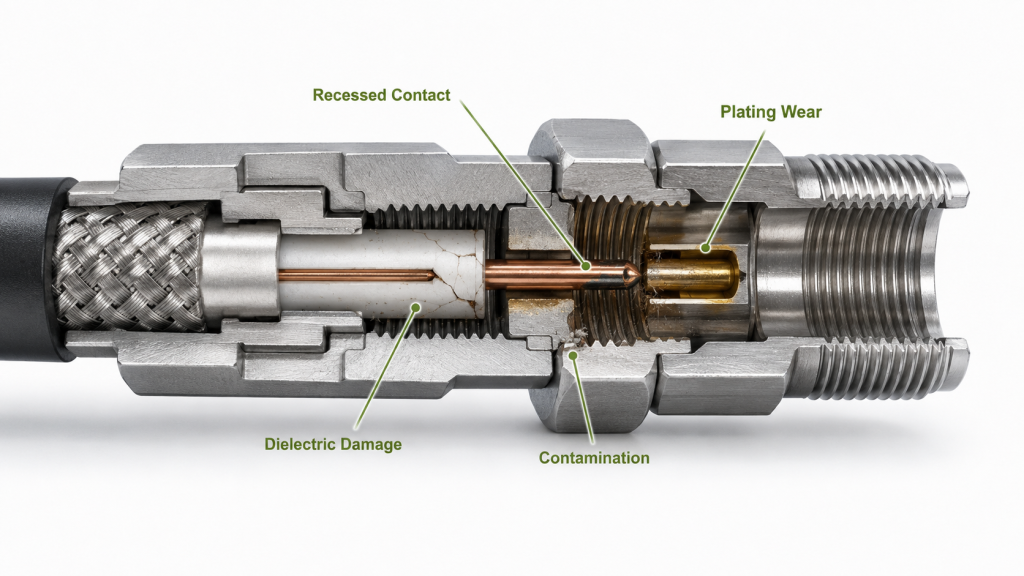
Inspect the actual mating boundary before increasing RF power. Look for defects that can change contact geometry or repeatability:
- bent, recessed, or misaligned center contact;
- incorrect mating depth;
- damaged or incomplete threads;
- loose panel or bulkhead mounting;
- cracked, displaced, contaminated, or heat-damaged dielectric;
- plating wear, oxidation, corrosion, pitting, or burn marks;
- metal particles, fibers, or cleaning residue;
- damaged or displaced gasket;
- incomplete mechanical seating;
- unsupported adapter or connector body.
Do not judge the interface from labels such as “high-quality connector” or “premium plating.” Use the connector, antenna, or interface specification that applies to the installed parts.
Torque is not the same as internal contact pressure
External coupling torque does not directly prove center-contact pressure. Connector systems use different spring contacts, gaskets, locking structures, panel arrangements, and mating geometries.
Follow the applicable mating, seating, locking, and torque procedure. Extra torque can damage threads, dielectric, gaskets, center-contact geometry, panel mounting, or body alignment. Too little seating force can leave the interface incomplete or mechanically unstable.
If the suspected defect is inside a crimped cable termination—such as shield capture, cable preparation, pin attachment, dielectric deformation, or strain relief—move that diagnosis to the RF PA connector crimping check.
Stop high-power testing when the interface is visibly unsafe
Do not continue increasing RF power when inspection finds:
- cracked or displaced dielectric;
- severe plating loss or deep corrosion;
- pitting, burn marks, or evidence of arcing;
- damaged threads or unstable connector body;
- a bent or recessed contact that prevents reliable mating;
- local overheating;
- moisture inside the interface or cable;
- seating that changes under light mechanical load.
Use the approved cleaning method for the connector system. Do not polish plated contact surfaces or use abrasive tools unless the service procedure explicitly permits it. Replace damaged parts when cleaning cannot restore a serviceable interface.
How Installation Stress and Remating Change the Interface
A feed interface can look stable on an open bench and change after the final cable route is fixed.
Mechanical conditions that can alter the mating boundary include:
- cable weight hanging from the connector;
- feeder and antenna misalignment;
- side load from a tight bend;
- unsupported adapters;
- mast or vehicle vibration;
- wind-driven cable movement;
- panel or bracket movement;
- thermal expansion;
- repeated mating during maintenance.
The connector should not carry the feeder’s weight. Support the cable independently, keep the first bend within the cable’s allowed radius, avoid sideways preload, and make sure the panel or bulkhead itself is stable.
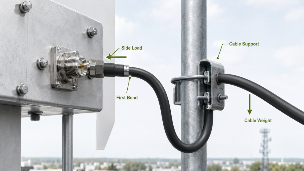
Remating is also a diagnostic variable. If a result improves after disconnecting and reconnecting the interface, record that as evidence of a repeatability problem. It is not a repair result until the final installed connection remains stable after the same mating procedure, support condition, and operating state are restored.
A cold connection may also behave differently after the connector body, panel, cable, and antenna structure warm at different rates. When the original symptom appears after warm-up, compare the fixed assembly before and after the required dwell without disturbing the connection between measurements.
Where rain, humidity, condensation, or resealing history tracks the fault, move the moisture diagnosis to the RF connector water-ingress check. A wet or corroded joint needs an environmental repair boundary, not more coupling torque.
How to Reproduce the Fault at a Defined Measurement Plane
Do not loosen, rotate, bend, or load the antenna feed interface while high-power RF is active.
Use a controlled sequence:
- Record the original frequency, RF operating condition, measurement plane, FWD/REV or VSWR evidence, and protection state needed to reproduce the symptom.
- Remove RF drive and confirm the path is safe to handle.
- Inspect the interface, its mounting, and the immediately adjacent cable support.
- Restore the specified mating and mechanical condition.
- Use low-power VNA, return-loss, or other approved interface measurements when the test plan calls for them.
- Substitute only one known-good compatible interface component when substitution is needed.
- Reinstall the final support and environmental protection.
- Restore RF power only after the assembly is secure.
- Repeat the required operating points without moving the connection.
- Compare the fixed-state cold and hot results when temperature is part of the original symptom.
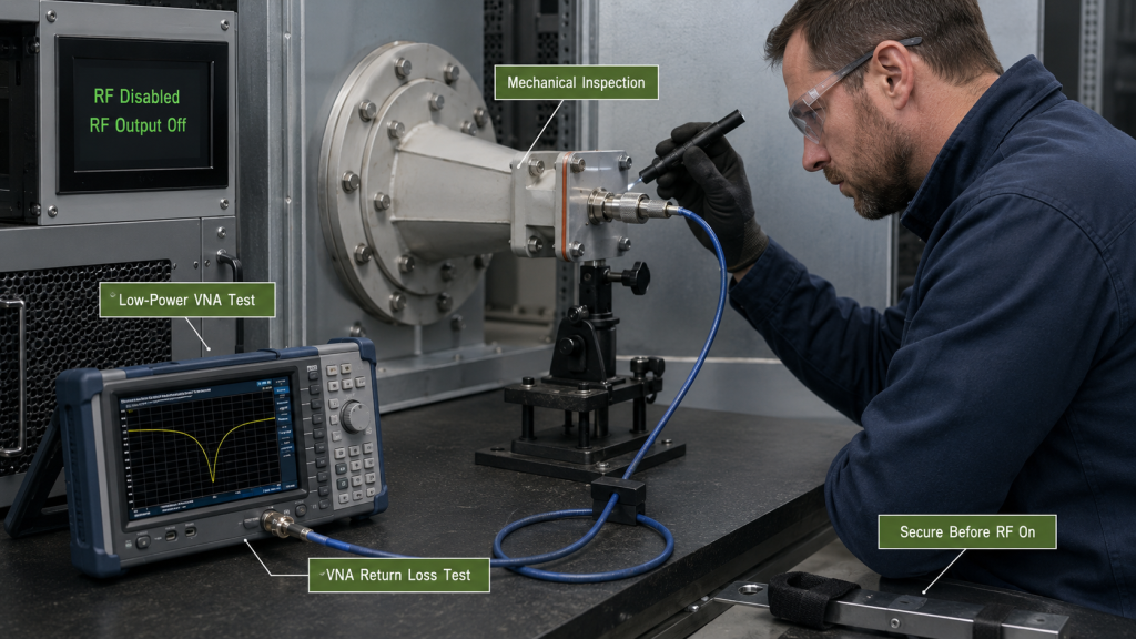
The reference plane must be named. A reading at the PA output port, cabinet output, feeder input, feed interface, or antenna input describes a different boundary. If a correction is applied, record the raw value, correction basis, corrected value, and the plane represented by the result.
Do not claim an isolated “interface loss” when the measurement still contains feeder cable, adapters, lightning-protection hardware, or other components that were not separately characterized.
What to record during the interface check
Use only the measurements needed for the decision. Typical fields include:
- frequency;
- RF operating point;
- FWD and REV, return loss, or VSWR as applicable;
- measurement reference plane;
- mating or support state;
- relevant interface temperature when thermal drift is suspected;
- test duration or dwell;
- alarm/protection state;
- before/after substitution or remating result.
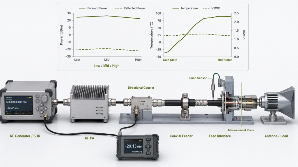
Keep the full PA/DC/thermal acceptance record in the broader system test. The interface record only needs enough detail to make the local conclusion traceable without duplicating that test program.
Pass/fail limits come from the project requirement, product evidence, or approved test plan. Do not apply one universal VSWR, return-loss, torque, temperature, or reflected-power limit to every antenna system.
What Evidence Is Enough to Accept or Reject the Feed Interface
An interface is not accepted because it looks clean, was tightened, or produced one good reading after reconnection.
The evidence should identify the actual installed interface and the condition that produced the result. Depending on project risk, record:
- PA or channel identity;
- antenna and feed-interface identity;
- connector or adapter part reference;
- final mechanical support and mating condition;
- applicable frequency points;
- measurement plane;
- defined RF operating condition;
- cold/hot or pre/post-maintenance comparison when relevant;
- local RF result needed by the acceptance rule;
- final alarm/protection state;
- photographs or assembly records when they are part of traceability.
Write the acceptance statement against that exact interface and test boundary:
With the identified antenna feed interface installed using the specified mating and support condition, the interface remained within the project-defined RF limits at the stated frequencies, reference plane, operating condition, and required dwell.

That statement does not approve the feeder, antenna radiation performance, complete installed RF chain, or every future maintenance condition.
Reject or retest the interface when the abnormal result follows the mating point, seating, support, remating, temperature state, or one replaceable interface component under a controlled comparison. Route the diagnosis elsewhere when the evidence follows a different boundary.
What to Define in the RFQ for the Antenna Feed Interface
Before the interface is specified, the RFQ should define only inputs that change the interface decision; post-test evidence belongs in the acceptance section above.
- antenna-side connector or feed-transition interface;
- mating cable or adapter interface;
- required frequency range or operating points;
- target PA-side RF condition and duty cycle relevant to the interface;
- mechanical support and allowable cable loading;
- mating, locking, and torque procedure when specified by the interface manufacturer;
- environmental exposure and sealing responsibility;
- measurement plane and required RF evidence;
- required hot-state or post-maintenance check;
- replacement criteria for contact, dielectric, plating, or mechanical damage;
- traceability required for the final installed interface.
Keep supplier responsibilities clear. RF SKYPOWER can review the submitted PA-side RF boundary, interface requirements, and evidence scope; final acceptance of the installed antenna path remains with the project-defined responsible party, while the antenna, cable, cabinet, and system integrator remain responsible for the parts and installation conditions they control.
Use these RFQ inputs as an engineering-review handoff; they do not establish that a particular PA module or antenna is suitable.
Conclusion
Reconnection alone is not a repair. Treat the interface as PASS only when the final mating point is mechanically supported, free of disqualifying damage, and repeatably stable at the defined measurement plane under the required RF and thermal condition.
If the result instead follows a cable termination, moisture path, antenna/load condition, or complete installed RF chain, move the investigation to that boundary rather than forcing an interface diagnosis.
For an interface or RFQ review, contact RF SKYPOWER engineering with the operating frequencies, target PA-side RF condition, antenna and connector interface, cable-support condition, environmental exposure, measurement plane, mismatch boundary, duty cycle, and required acceptance evidence.