










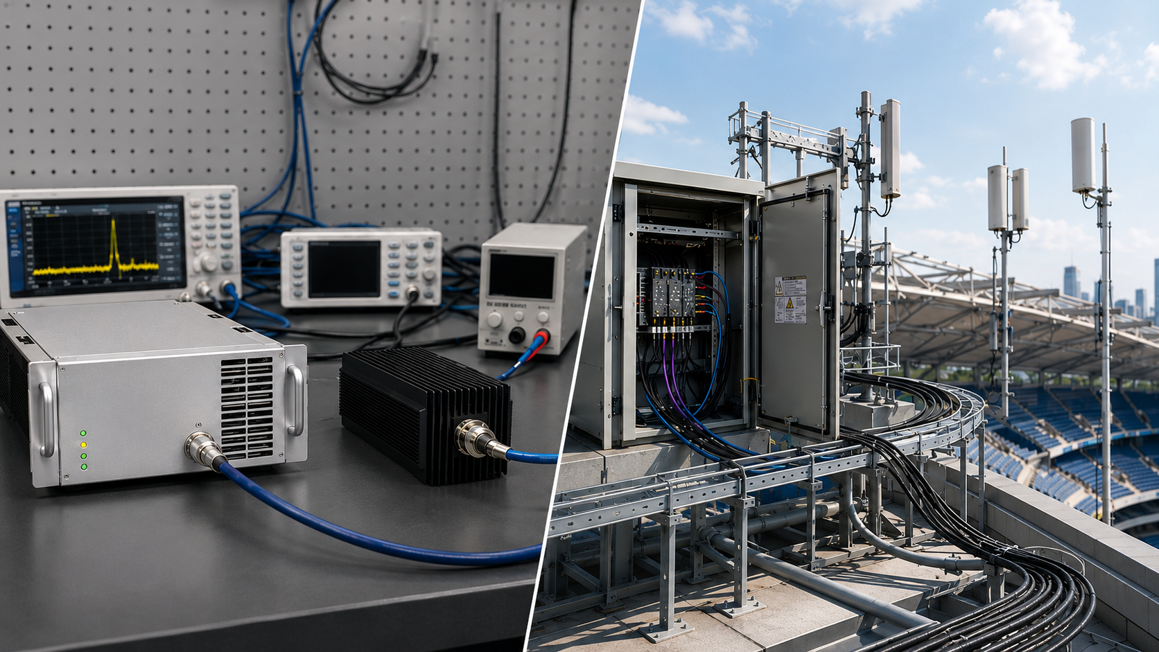
An RF PA can meet its target output on a qualified dummy-load setup and show a different result after the real antenna load and installed RF path are connected. The field reading may be lower, reflected power may change, or protection may become active—but that change does not yet identify where the difference comes from.
A bench result and an installed-path result are only comparable when the relevant operating and measurement boundaries are clear. Otherwise, downstream path loss can be mistaken for PA output loss, a change in REV can be overinterpreted as proof of mismatch severity, or a protection state can be treated as proof of a module or antenna-path fault.
So after the real antenna load is connected, what should engineers compare before deciding whether the change comes from the PA, the installed RF path, the reflection condition, or the measurement boundary?
1. What the Dummy-Load Baseline Actually Establishes
A qualified dummy load provides a controlled reference condition for checking the RF PA before the installed antenna path is introduced.
Depending on the test plan, that baseline may establish:
- RF output at a defined PA-side reference plane;
- frequency-point or swept-frequency performance;
- RF input drive;
- Vdc and Idc;
- operating duration;
- duty cycle;
- thermal condition;
- protection state;
- FWD and REV behavior under the qualified load.
That baseline is valuable because it provides a known comparison point.
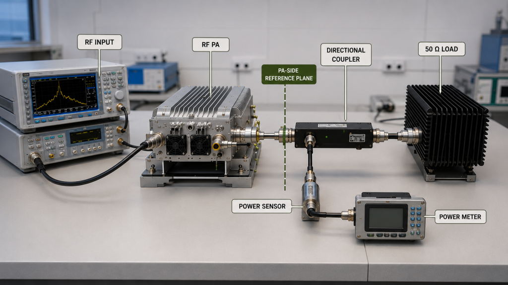
It does not automatically prove what the system will measure after adding:
- feeders;
- connectors;
- filters;
- switches;
- combiners;
- couplers;
- antenna branches;
- or the final antenna load.
After the installed antenna path is connected, the PA sees a different load boundary from the qualified dummy-load baseline.
The engineering question is therefore not simply whether the new reading is higher or lower. It is whether the test conditions and reference planes are sufficiently controlled to explain what changed.
For the broader relationship between dummy-load testing and installed-path validation, see the separate RF-chain acceptance boundary.
2. What Can Change After the Real Antenna Path Is Connected
An installed antenna path can change the reported result through several different mechanisms.
These mechanisms should not be combined into one generic “output loss.”
Path insertion loss
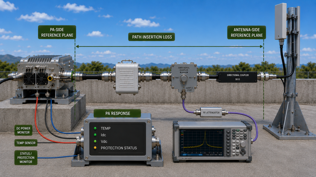
If power is measured farther downstream from the PA, feeder, connector, filter, switch, or other path loss can reduce the forward power measured at that later reference plane.
That does not automatically prove that PA-port Pout decreased.
For example, a lower reading at an antenna-side reference plane may be consistent with normal path loss while the PA-side forward output remains substantially unchanged.
This is why the measurement reference plane must be stated before comparing two RF power readings.
Do not assume that a path-loss value measured under a matched condition can always be applied directly to convert PA-port power into antenna-side forward or accepted power under mismatch. The correction method must be valid for the stated reference planes and installed load condition.
Mismatch and reflected power
A real antenna path can present a different impedance condition from the qualified dummy-load baseline.
That may change:
- FWD;
- REV;
- calculated or reported VSWR;
- return-loss behavior;
- or the PA operating condition.
A change in REV can indicate a different reflection condition, but REV should not be interpreted alone.
If FWD also changes, a higher or lower REV value by itself does not show whether the reflection ratio became better or worse.
Compare FWD and REV at the same defined reference plane and operating state, and use the corresponding reflection ratio, return loss, or VSWR where appropriate.
Where the required engineering decision involves accepted power rather than forward power alone, the distinction should be handled explicitly. See usable RF output power for that separate calculation boundary.
PA load-dependent response
The PA itself may also change operating state when the installed load changes.
Depending on the module architecture and protection design, this may appear as:
- changed forward output;
- different current behavior;
- alarm activation;
- foldback;
- shutdown;
- or recovery after the load condition changes.
This is different from simple downstream insertion loss.
The measured result should therefore be separated into three questions:
- Did power change because the measurement plane moved downstream through a lossy RF path?
- Did the reflection condition change relative to the qualified baseline?
- Did the PA operating or protection state itself change?
Only after those questions are separated should a root cause be assigned.
Representative installed-site conditions
In a complex fixed-site C-UAS installation, longer feeders, additional transitions, different antenna branches, or nearby structures can create installed-path conditions that differ from the controlled bench setup.
These are conditions to verify, not evidence that a specific site or PA will fail.
The purpose of the installed-path test is to measure the actual project boundary rather than assume that every field installation behaves the same way.
3. How to Separate Path Loss, Mismatch, and PA Response
The most useful comparison keeps the electrical and measurement boundaries as consistent as practical.
Start with the qualified dummy-load baseline, then record the installed-path result under the corresponding operating condition.
Compare power at defined reference planes
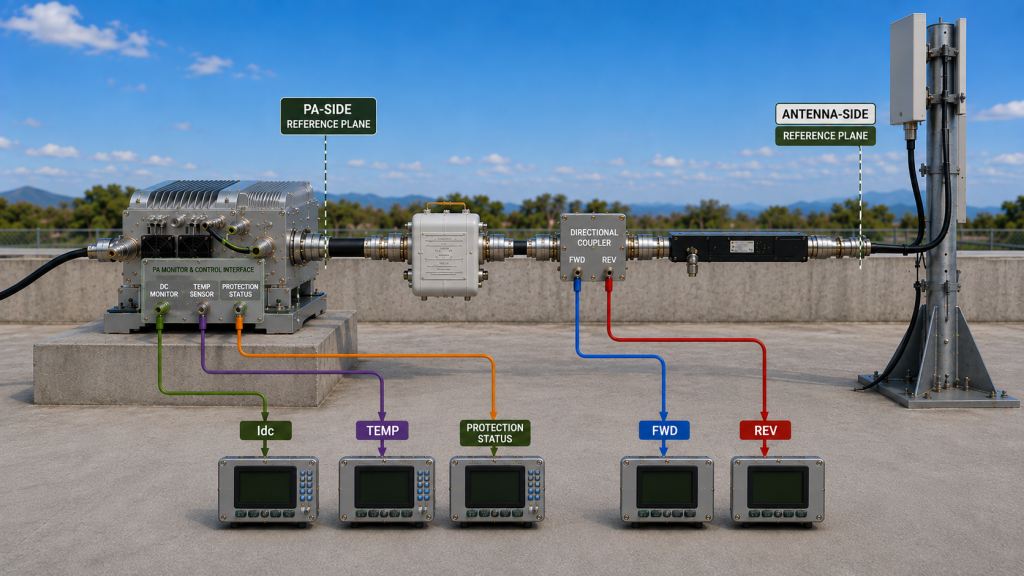
Do not compare a PA-port reading directly with an antenna-side reading and call the difference “PA output loss.”
Instead, identify:
- where PA-side forward power is measured;
- where antenna-side power is measured;
- which RF-path losses lie between them;
- whether those losses were characterized under conditions relevant to the installed load;
- whether they are measured, estimated, or corrected;
- and what quantity the acceptance requirement actually uses.
PA-port Pout and antenna-side power are different measurements unless the path boundary and correction method are explicitly defined.
If mismatch is material, do not assume that a scalar loss value obtained under a matched condition fully represents the real relationship between PA-port power, antenna-side forward power, and accepted power.
Compare FWD and REV under compatible conditions
FWD and REV values should be compared with attention to:
- frequency;
- RF input condition;
- PA operating state;
- reference plane;
- measurement timing;
- detector response;
- averaging or peak method where relevant;
- sensor or coupler calibration;
- directional-coupler directivity where it materially affects low-level REV measurement.
When FWD and REV are compared, use the same defined reference plane, a comparable operating state, compatible timing and power definitions, and measurement hardware suitable for the reflected-power range being evaluated.
A change in REV can justify further investigation of the installed load or RF path, but it should not be treated as a root-cause conclusion by itself.
Treat Idc as supporting evidence
DC current may change when the load condition or protection state changes, but the direction of the current change is architecture- and operating-state-dependent.
Idc may increase, decrease, or remain relatively stable depending on:
- PA architecture;
- bias behavior;
- control loops;
- protection logic;
- RF drive;
- thermal state;
- and the actual load condition.
A current change is supporting evidence, not a standalone mismatch diagnosis.
Correlate Idc with:
- FWD;
- REV;
- Vdc;
- temperature;
- protection status;
- and RF output.
Treat temperature as correlated evidence
A changed load condition may coincide with a different thermal result, particularly if the PA operating point or protection response changes.
Temperature alone does not prove that reflected power caused the thermal change.
Compare thermal data under a stated:
- frequency;
- RF output condition;
- duty cycle;
- cooling condition;
- ambient condition;
- and test duration.
Treat protection states as evidence, not root cause
A protection event shows that the sensing or control system reported or latched a defined protection state.
It does not by itself prove that:
- the underlying RF condition has been independently confirmed;
- the sensor value was valid;
- the configured threshold or delay was appropriate;
- the installed RF path was the root cause;
- or the PA hardware was defective.
The event should be correlated with:
- FWD;
- REV;
- sensor or detector state;
- threshold;
- delay or filtering;
- alarm timestamp;
- control state;
- reset or latch behavior.
If reflected-power alarms become the primary troubleshooting problem after installation, that root-cause isolation belongs in the dedicated reflected power alarm workflow.
4. What Evidence Should Be Compared on the Same Test Boundary
The strongest diagnosis comes from synchronized evidence rather than from one power reading or one alarm screenshot.
| Observed Change | What It Can Mean | Boundary to Hold Constant | Evidence Needed |
|---|---|---|---|
| Downstream RF power is lower | Installed-path loss, a non-equivalent measurement reference plane, or an actual PA-side output change | Frequency, Pin, operating state, measurement plane | PA-side Pout, antenna-side measurement, path-loss data, correction method |
| REV changes relative to FWD | Different reflection condition or measurement boundary | Same reference plane, frequency, timing, detector method | FWD, REV, return loss / VSWR, sensor or coupler method, branch / antenna ID |
| FWD changes | PA operating state, load interaction, protection response, or different measurement boundary | Pin, Vdc, thermal state, reference plane | FWD, Pin, Vdc, Idc, protection state |
| Protection becomes active | Protection logic reported or latched a defined state | Load, frequency, timing, protection configuration | Alarm timestamp, FWD / REV, sensor state, threshold, delay / filtering, control state |
| Idc changes | Different PA operating or protection state | Pin, Vdc, frequency, thermal condition | Idc synchronized with RF and protection data |
| Temperature changes | Different operating point, cooling state, duration, or load-related behavior | Duty cycle, duration, cooling, ambient | Temperature trend, RF data, Idc, protection state |
The important point is not to force every system into one identical test method.
The important point is to preserve enough measurement context that two observations can actually be compared.
Keep measurements tied to the actual configuration
Installed-path evidence should identify the configuration that produced the result.
Useful identifiers can include:
- PA module S/N;
- antenna or branch ID;
- feeder or RF-path configuration;
- frequency;
- signal condition;
- RF input condition;
- PA-side reference plane;
- antenna-side reference plane;
- FWD / REV acquisition method;
- sensor or coupler calibration where relevant;
- Vdc;
- operating duration;
- thermal condition;
- protection state.
For traceable acceptance:
One Unit → One Serial Number → One Test Dataset → One Test Report → Traceable Acceptance Evidence
S/N linkage identifies which delivered unit the data belongs to. It does not replace the need to define the test condition.
When a broader shipment-acceptance record is required, S/N-linked evidence can be reviewed together with the installed-path test result.
5. How to Define Real-Antenna Acceptance in the RFQ
A useful RFQ should not ask only:
“Will the PA work with our antenna?”
That question does not define what result must be demonstrated or where it must be measured.
Instead, define the actual installed-load acceptance boundary.
RFQ Checklist
| RFQ Item | Customer Input Needed |
|---|---|
| Frequency requirement | Required band and key test frequency points |
| PA-port output target | Required RF output at the defined PA output reference plane |
| Antenna-side power requirement | Define whether acceptance uses forward power at the antenna input, net accepted power at a stated plane, or another explicitly defined system metric |
| RF input condition | Required Pin, drive level, waveform, or other agreed input condition |
| Installed RF path | Feeder, connector, filter, switch, combiner, coupler, and branch configuration where applicable |
| RF-path loss | Measured, calculated, or corrected loss method, reference planes, and applicable load condition |
| FWD / REV measurement | Reference plane, sensor / coupler location, calibration, timing, detector or averaging method, directivity where relevant, and applicable power definition |
| VSWR / return-loss boundary | Required operating or protection boundary |
| DC input | Project-defined Vdc condition and relevant measurement point |
| Duty cycle | CW or specified operating duty cycle |
| Operating duration | Required test duration and stabilization condition |
| Thermal condition | Cooling method, ambient boundary, and relevant temperature point |
| Protection behavior | Alarm, foldback, shutdown, latch, reset, or recovery expectation where applicable |
| Configuration identity | PA S/N, antenna / branch ID, and installed-path configuration |
| Acceptance evidence | Required synchronized measurements, plots, logs, and report format |
The RFQ should define only the conditions that materially affect the project decision.
For some systems, PA-port output under a qualified load is the primary module acceptance requirement, while installed-path verification is handled separately.
For other systems, the customer may require an antenna-side measurement after the actual feeder and switching path is installed.
Those are different acceptance boundaries and should be written separately.
Do not let an antenna-side number hide the measurement definition
“Antenna-end output” is not precise enough by itself.
The required quantity might mean:
- forward power at the antenna input;
- net accepted RF power at a defined plane;
- corrected forward power after a valid path-loss treatment;
- or another system-level metric.
It should not be assumed to mean radiated performance, EIRP, or any other quantity unless the RFQ explicitly defines that requirement.
FAQ
Why can RF PA output look different after connecting the real antenna path?
The observed result can change because of RF-path insertion loss, a different reflection condition, a change in PA operating state, or a different measurement reference plane.
These mechanisms should be separated before assigning the change to the PA or antenna path.
Does higher VSWR mean the RF PA is bad?
No conclusion about PA hardware should be made from VSWR alone.
Higher VSWR indicates a different reflection condition at the stated measurement boundary when the measurement itself is valid. The reflection condition may originate in the antenna or installed RF path, while the PA may respond through output change, alarm, foldback, or shutdown.
The relevant FWD, REV, reference plane, operating state, and protection evidence should be correlated before assigning the cause.
Which reference plane should be used for RF PA approval?
The reference plane should match the decision being made.
PA module output can be accepted at the defined PA output port, while installed-system verification may use a separate antenna-side reference plane.
The two should not be treated as the same power measurement unless the RF-path boundary and correction method are explicitly defined.
What evidence should be captured during a real-antenna test?
Capture the measurements needed to reconstruct the same event and configuration.
Depending on the project, this may include PA-side output, antenna-side power, FWD, REV, VSWR or return loss, Pin, Vdc, Idc, temperature, protection state, frequency, operating duration, PA S/N, antenna or branch ID, and RF-path configuration.
The key evidence should be synchronized or otherwise traceable to the same operating condition.
Conclusion
RF PA output should be verified with a real antenna load by separating installed-path loss, reflection behavior, and any load-dependent PA response before assigning a root cause.
A lower downstream power reading does not automatically mean PA-port Pout has fallen. A change in REV should be interpreted relative to FWD and the measurement boundary rather than used alone as proof of mismatch severity. A protection event shows that the system reported or latched a protection state; it does not by itself prove which physical condition or RF-path element caused it.
The comparison becomes meaningful when the engineer keeps the relevant frequency, RF input, reference plane, measurement timing, path-loss treatment, DC, thermal, and protection boundaries clear and ties the resulting data to the actual installed configuration.
Once the installed-load boundary is defined, a custom RF power amplifier module can be reviewed against the project’s required frequency, PA-port output, installed RF path, reflection limit, thermal state, protection behavior, and acceptance evidence.
For RFQ review, provide the required frequency points, PA-port output target, installed RF-path layout, antenna-side measurement requirement, feeder and connector path, VSWR or return-loss boundary, FWD / REV measurement method, project-defined Vdc condition, duty cycle, operating duration, thermal requirement, protection criteria, antenna or branch ID, and required S/N-linked test evidence.