










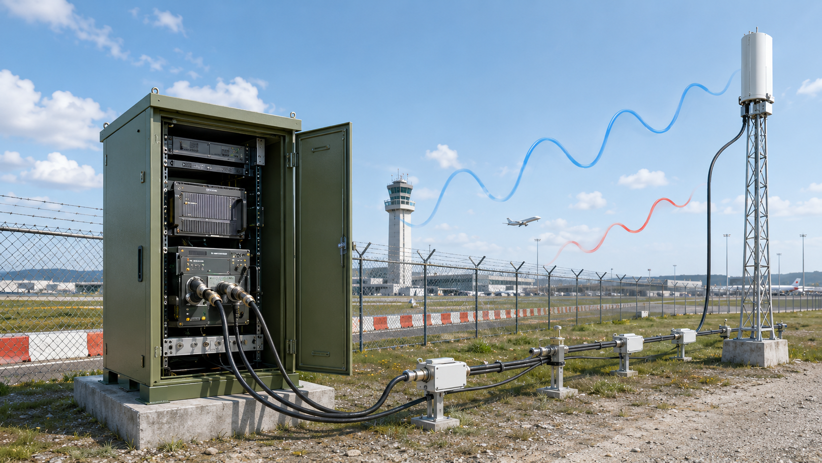
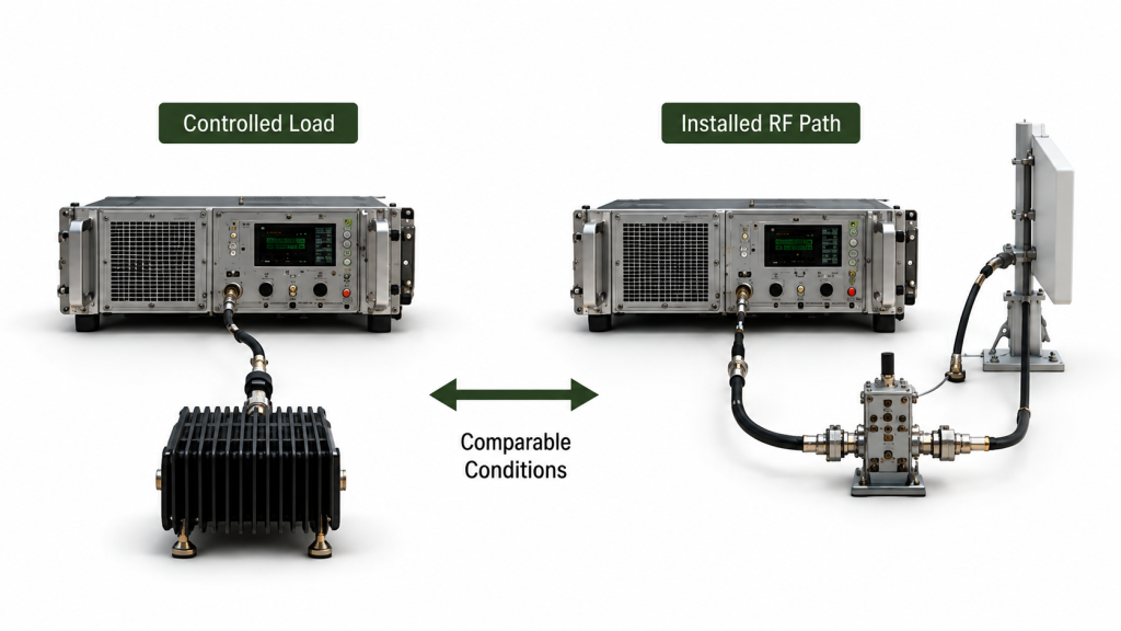
A reflected power alarm that appears only after a C-UAS RF PA is connected to the installed antenna path is a symptom, not a root-cause diagnosis. The same module may remain stable on a controlled dummy load yet alarm after the feeder, connectors, lightning protection, adapters, or antenna are added.
For a custom RF Power Amplifier Module, the useful comparison is not simply “bench passed, field failed.” The relevant frequency, RF operating condition, measurement boundary, and protection configuration must remain clear while the PA baseline and installed path are compared.
So when the alarm appears after installation, what evidence actually separates an RF PA problem from an installed-path mismatch or a protection-condition problem?
1. Why a Bench Pass Does Not Identify the Installed Alarm Cause
A PA that remains stable on a known-good load suitable for the relevant frequency and RF power has demonstrated behavior under that controlled test boundary. It has not automatically demonstrated the same behavior after the full installed RF path is added.
The installed path may include:
- cabinet RF routing;
- bulkhead connectors;
- adapters;
- feeder cable;
- lightning protection;
- outdoor connectors;
- antenna feed interfaces;
- the antenna itself.
Impedance discontinuities, poor terminations, damaged RF interfaces, or antenna mismatch within that chain can increase reflected power seen toward the PA.
That does not mean every post-installation alarm is an RF-path fault.
The bench and installed tests may also differ in:
- frequency;
- Actual Pin or commanded drive;
- measured Pout or FWD condition;
- DC supply condition;
- thermal state;
- cooling condition;
- measurement method;
- protection threshold or configuration.
A reflected power alarm that appears after installation should therefore be treated as a change-of-boundary symptom, not as automatic proof of either an RF PA fault or an installed-path fault.
The first task is to reproduce the event under a controlled condition and determine which changed boundary makes the alarm appear.
For projects still defining installation requirements before deployment, broader RF PA VSWR field failure prevention should be handled separately from this post-installation diagnostic process.
2. How to Isolate the PA Baseline From the Installed RF Path
Do not start by replacing the PA.
Start by separating the amplifier from the installed RF path and rebuilding the path in controlled steps.
A practical isolation sequence is:
- Connect the PA to a known-good load suitable for the relevant frequency and RF power.
- Repeat the test with the intended short RF test cable.
- Test through the cabinet RF output or bulkhead interface.
- Add the feeder cable.
- Add lightning protection, adapters, and outdoor connectors.
- Connect the actual antenna last.
The purpose is not simply to obtain another Pass or Fail result.
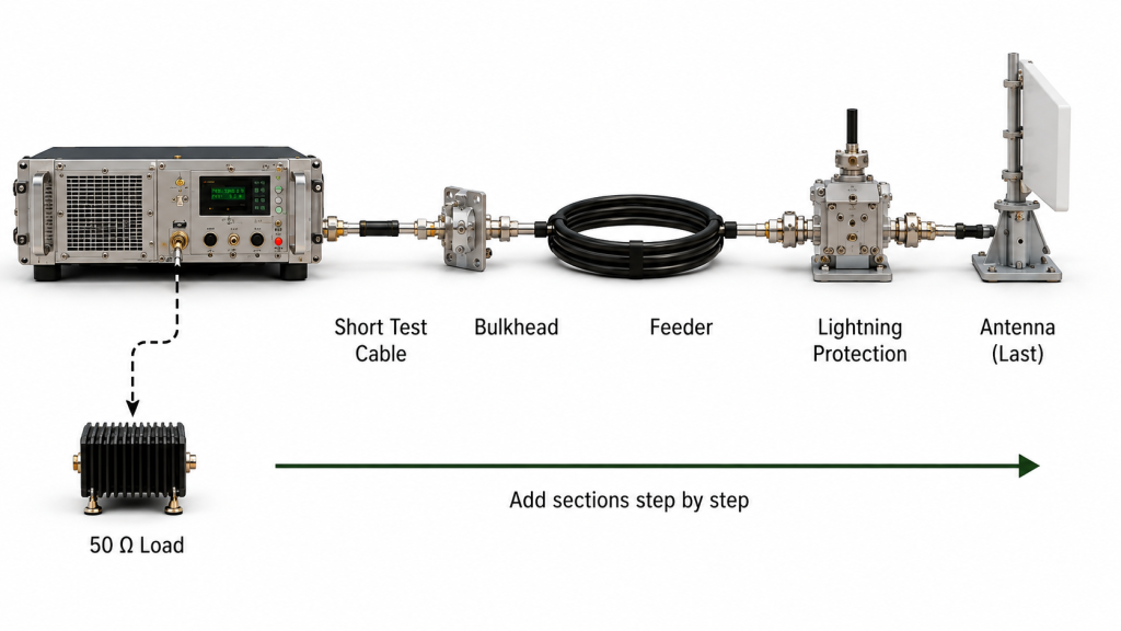
The purpose is to identify where the behavior changes.
If the alarm remains reproducible with the PA connected to the controlled load, the investigation should not continue downstream as if the installed antenna path had already been proven responsible.
If the PA remains stable under the controlled baseline but the alarm appears after a specific path section is added, the evidence shifts suspicion toward that section or its interfaces.
It still does not identify the failed component by itself.
Keep the Operating Boundary Comparable
Keep the relevant:
- frequency;
- Actual Pin or commanded drive, where available;
- measured Pout or FWD condition;
- Vdc / Idc where relevant;
- load definition;
- cooling condition;
- thermal state;
- protection configuration
as comparable as practical while switching between the controlled baseline and installed RF path.
Do not treat two tests as comparable only because the commanded output is the same.
If protection back-off, controller action, or another control response changes Actual Pin, Pout, or FWD power, that change must be considered before the installed RF path is assigned as the cause.
Likewise, do not compare a low-power dummy-load result with a higher-power installed-path alarm and treat the difference as proof of an RF-path fault.
Different frequencies, thermal states, or protection settings can also change the result.
When the alarm changes after cable repositioning, cabinet closure, or clamp installation, an RF cable bending check can help determine whether the final routed cable or a mechanically stressed interface needs further inspection.
3. How to Correlate FWD / REV / VSWR With the Alarm Event
The alarm flag alone is not enough.
A useful troubleshooting record should show what the RF system was doing when the event occurred.
Record, where applicable:
- Forward Power;
- Reflected Power;
- VSWR / SWR;
- frequency;
- Actual Pin or commanded drive;
- measured Pout or FWD condition;
- alarm timestamp;
- load condition;
- warning / back-off / shutdown / recovery state;
- Vdc / Idc;
- relevant temperature;
- controller or status feedback.
Identify the Measurement Source
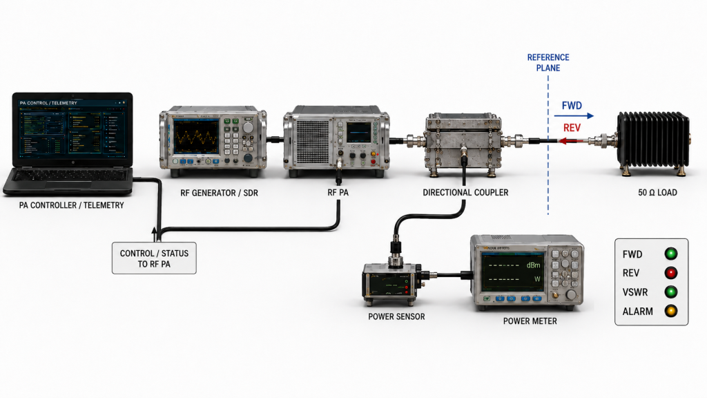
FWD and REV values are only useful when their source is clear.
The record should identify whether they come from:
- internal PA telemetry;
- an internal directional sensing path;
- an external directional coupler;
- a power sensor or meter;
- another system monitoring point.
It should also state whether the values are raw readings or corrected measurements at a defined reference plane.
Do not compare internal telemetry and an externally corrected measurement as if they were necessarily the same quantity at the same plane.
The same rule applies to VSWR or reflected-power limits: the acceptance or protection rule should be tied to the measurement definition actually used by the system.
Separate Absolute Reflected Power From Normalized Mismatch
A rise in absolute REV power does not automatically mean the VSWR has become worse.
If FWD power increases while the load reflection coefficient remains similar, absolute reflected power can also increase.
The troubleshooting record should therefore distinguish between:
- an absolute REV-power threshold;
- the ratio between reflected and forward power;
- VSWR or return loss;
- a protection threshold based on one of those quantities;
- a genuine change in the load mismatch.
This distinction is especially important when the alarm appears only at higher RF output.
Read the Pattern, Not Just the Alarm Flag
| Observed Pattern | Next Controlled Test | Evidence That Would Shift Suspicion |
|---|---|---|
| Alarm appears only after the installed antenna path is connected | Return to the controlled load, then reconnect path sections | Alarm disappears on baseline and returns after a repeatable path section is added |
| Alarm appears at one frequency | Repeat baseline and installed-path test at the same target frequency | REV / VSWR behavior changes at that frequency only after the path is added |
| Alarm appears after cabinet assembly | Inspect bulkhead, adapter, cable routing, and connector stress | Behavior changes with cabinet routing or interface condition |
| Alarm appears after rain or outdoor exposure | Inspect exposed connectors, sealing, feedthroughs, and lightning protection | Alarm or mismatch follows moisture-affected hardware or changes after repair |
| Alarm appears only at higher RF output | Repeat controlled power steps while logging FWD, REV, VSWR, and protection state | Determine whether the alarm follows an absolute REV-power threshold while VSWR remains similar, or whether the normalized mismatch itself worsens as RF output increases |
| Alarm follows one removable RF component | Repeat with a known-good replacement under the same boundary | Symptom follows the component rather than the PA |
| Alarm remains on the controlled load | Recheck PA, sensing path, test setup, and protection configuration | Alarm remains independent of the installed RF path |
The strongest troubleshooting record does not say only:
“Reflected power alarm occurred.”
It shows the RF operating condition, measurement source, measurement boundary, path configuration, and protection response associated with the event.
When status reporting is ambiguous, the PA alarm should also be interpreted through the correct RF PA status feedback mapping rather than assuming every shutdown or alarm code represents reflected power.
4. Which Installation Changes Should Be Rechecked After the Alarm?
A post-installation alarm can appear after the RF path changes even when the PA itself has not changed.
Relevant changes may include:
- feeder replacement;
- cable repositioning;
- tighter bend or mechanical compression;
- connector re-mating;
- adapter replacement;
- bulkhead installation;
- lightning protector installation or replacement;
- antenna replacement;
- antenna feed-point work;
- waterproofing or resealing;
- cabinet closure;
- mechanical pull on the cable or connector.
These changes should be treated as changes to the installed test boundary.
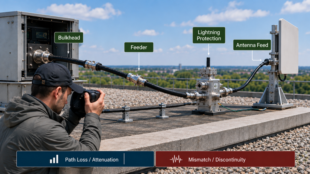
Do Not Treat Cable Loss and Reflected Power as the Same Problem
A lossy feeder can reduce antenna-end power without necessarily creating a large reflected-power alarm.
Reflected power is more directly associated with impedance mismatch or discontinuity.
The troubleshooting process should therefore distinguish:
- attenuation through the RF path;
- mismatch seen toward the PA;
- local connector or adapter discontinuity;
- antenna mismatch;
- protection response.
That distinction prevents a simple insertion-loss problem from being mislabeled as a reflected-power root cause.
If the remaining suspect is the antenna-side connection, use an RF PA antenna feed interface check before replacing either the PA or antenna.
If the event follows rain, condensation, resealing, or outdoor maintenance, inspect RF connector sealing and water-ingress risks as a separate physical-path check.
5. When Should the Investigation Return to the RF PA or Protection Threshold?
Troubleshooting should not become a process of endlessly replacing downstream RF components.
If the reflected power alarm remains reproducible with a known-good load under the same approved operating boundary, the investigation should return to the PA, sensing path, test setup, or protection configuration.
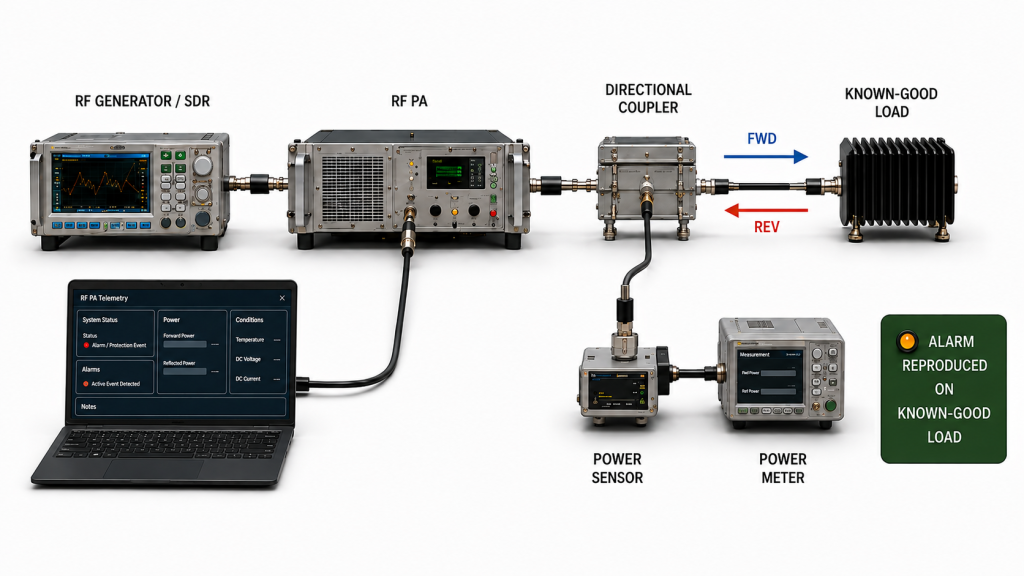
Check whether the result changes with:
- known-good load;
- RF test cable;
- measurement instrument;
- sensing or coupler path;
- frequency;
- Actual Pin or commanded drive;
- measured Pout or FWD condition;
- PA configuration;
- threshold or protection file;
- hardware or firmware state where applicable.
Separate a Protection Response From the Root Cause
A warning, output back-off, or shutdown can be the expected protection response to a load condition.
That response does not by itself prove what caused the reflected power.
Likewise, an alarm that disappears after reducing RF output does not prove that the PA was defective or that the installed path was defective.
It shows that the event is operating-condition dependent and should be interpreted together with the corresponding FWD / REV / VSWR data, measurement source, and protection configuration.
Where threshold files or protection settings are part of the acceptance configuration, compare the event against the approved RF PA alarm threshold file.
The key question is:
Did the PA respond incorrectly, or did it correctly respond to a load or sensing condition that still needs to be identified?
That distinction should be made before hardware is replaced.
6. What Evidence Should Be Saved for Retest and Acceptance?
Once the alarm has been isolated or corrected, the troubleshooting record should support a repeatable retest.
For a shipment or project where the event affects acceptance, save:
- delivered model and S/N;
- applicable hardware / firmware / configuration revision;
- target frequency point;
- Actual Pin or commanded drive where relevant;
- measured Pout or FWD condition;
- load condition;
- cooling and thermal state where relevant;
- measurement source;
- measurement reference plane where applicable;
- FWD / REV / VSWR record;
- alarm timestamp;
- Vdc / Idc where relevant;
- dummy-load baseline;
- installed RF-path configuration;
- suspect path section;
- corrective action;
- post-correction retest result.
The record should make clear which evidence belongs to the PA itself and which evidence belongs to the installed system boundary.
A batch-level or configuration-level validation should not be presented as if it were an individual event record for a specific delivered unit.
When the event affects shipment or field acceptance, connect the troubleshooting record to the applicable C-UAS RF PA acceptance checklist and keep the evidence linked to the delivered S/N where unit-level evidence is required.
A troubleshooting case is not fully closed unless the record shows what changed, what was tested again, and under which operating and measurement boundary the retest passed.
FAQ
Does a reflected power alarm prove the RF PA is defective?
No. A reflected power alarm indicates that the PA or controller reported a reflected-power-related protection state under its configured sensing and threshold logic. The alarm alone does not prove the actual RF load condition or identify the root cause.
The cause still has to be isolated between the PA, test setup, installed RF path, sensing method, and protection configuration.
Why can a PA pass on a dummy load but alarm on the installed antenna path?
A dummy load and an installed antenna chain are different RF boundaries. The installed path adds feeder cable, connectors, adapters, lightning protection, feed interfaces, and the antenna.
If the tests are performed under comparable frequency, drive, output, supply, thermal, and protection conditions, a repeatable change after one of those sections is added helps narrow the investigation.
What evidence should be saved before replacing the PA or RF-path hardware?
Save the frequency, Actual Pin or commanded drive where relevant, Pout or FWD condition, FWD / REV / VSWR data, measurement source, reference plane where applicable, alarm timestamp, protection status, S/N, relevant configuration, controlled-load baseline, installed-path condition, and isolation-test result.
Replacement decisions should follow that evidence rather than the alarm flag alone.
Conclusion
A reflected power alarm after C-UAS installation should not be treated automatically as either an RF PA failure or an installed RF-path failure.
The correct diagnostic process is to establish a controlled PA baseline, keep the relevant frequency, drive, RF output, supply, thermal state, measurement boundary, and protection configuration comparable, reconnect the installed RF chain in controlled sections, and correlate the alarm with FWD / REV / VSWR and the protection response.
If the alarm disappears on the controlled load and returns repeatably after a defined installed-path section is added, the evidence shifts suspicion toward that section. If the alarm remains on the controlled load under the same operating boundary, the investigation should return to the PA, sensing path, test setup, or protection configuration.
When the event appears only at higher RF power, do not treat higher absolute REV power alone as proof that VSWR has worsened. Determine whether an absolute reflected-power threshold is being crossed or whether the normalized mismatch itself is changing.
Before the issue is closed, save the S/N-linked alarm record, test boundary, corrective action, and retest evidence so the result can support later maintenance or acceptance decisions.
For a custom RF Power Amplifier Module, define the target frequency range, PA-port output requirement, installed RF path, feeder length, connector and lightning-protection details, allowed VSWR or reflected-power condition, protection configuration, and required test-report format in the RFQ.
Contact us with these project requirements together with the alarm log and FWD / REV / VSWR evidence for your C-UAS RF PA project.