










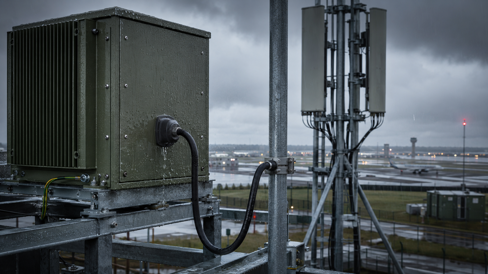
RF connector water ingress usually starts with the complete outdoor joint. Moisture can enter at the mating interface, cable-to-connector transition, external weatherproof layer, cabinet feedthrough, or another opening that lets water reach the RF path. Adding tape over a faulty boundary does not remove that entry path.
A joint can look tight and still be unsafe for service. The useful test is whether the final outdoor connection remains dry, mechanically supported, and electrically stable under the frequency, RF power, thermal state, and environmental conditions that matter to the installation.
For an RF PA path, prevention and diagnosis should follow one boundary: find how moisture can enter, remove the condition that allows it, decide whether any damaged hardware must be replaced, rebuild the seal, and then repeat the RF checks that can show whether the repaired path is stable.
1. What Water Ingress Changes in an RF PA Path
Water does not need to create a direct short to disturb RF behavior. Moisture around a connector can change local impedance, contact resistance, dielectric behavior, shield continuity, insertion loss, or the stability of a mating interface. Under RF power, those changes can appear as higher reflected power, VSWR drift, output reduction, local heating, or intermittent protection alarms.
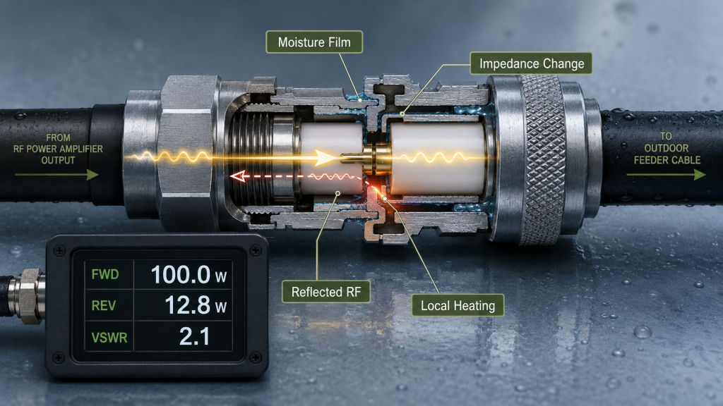
The symptom is useful, but it is not a component diagnosis. A reflected-power alarm after rain can come from a wet connector, a feedthrough, a cable section, an antenna-side interface, or another installed-path boundary. A PA that reports the alarm may be responding correctly to the load it sees.
| Observation | What it supports | What it does not prove |
|---|---|---|
| REV or VSWR rises after rain | An environmental condition may be changing the RF path | Which connector or component is wet |
| Fault improves after drying | Moisture is a plausible contributor | That the joint is repaired |
| Connector temperature rises | Contact or mismatch stress needs investigation | That water is the only cause |
| One branch repeats the fault | A branch-specific path problem is more likely | That the PA module is defective |
| Dummy-load baseline is stable | The controlled PA-side path is useful as a reference | That the installed antenna path is acceptable |
If reflected-power or VSWR behavior remains unstable after the moisture-related joint has been ruled out or repaired, check the broader RF PA VSWR field-failure causes, including other installed-path conditions that can raise reflected power.
2. Where Water Enters an Outdoor RF Connector Assembly
An outdoor RF joint has several moisture boundaries. Inspecting only the front of the connector can miss the actual entry path.
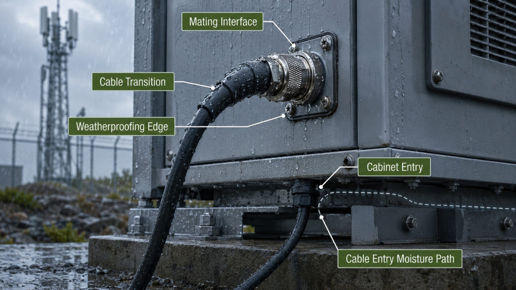
Mated interface
Water can reach the mating surface when the connector is incompletely seated, the coupling mechanism is loose, a gasket or O-ring is missing or damaged, the sealing surface is contaminated, or the two connector parts are not compatible.
A wet mating interface may also show corrosion, pitting, plating damage, dielectric contamination, or unstable contact. Those findings matter because resealing damaged hardware can hide the entry point without restoring a reliable RF transition.
Cable-to-connector transition
Moisture can move along the cable jacket, shield structure, rear connector body, crimp area, or heat-shrink edge. Water can also migrate inside a cable after the outer jacket or termination has been compromised.
If inspection instead points to pin position, shield capture, dielectric deformation, crimp quality, or strain-relief workmanship, the RF PA connector crimping guide can help separate termination defects from moisture damage.
External weatherproof layer
Tape, cold-shrink, boots, molded seals, or other external weatherproofing can fail when overlap is insufficient, adhesion is poor, UV exposure has degraded the material, the wrap direction sheds water toward the joint, cable movement works an edge loose, or the seal is reused after maintenance.
A continuous outer layer can still trap moisture that was present during assembly. The connector and surrounding surfaces need to be clean and dry before the seal is rebuilt.
Cabinet entry and feedthrough
The RF connector may not be the original entry point. Check bulkhead mounting, feedthroughs, cable glands, cabinet seams, lightning-protection interfaces, drainage paths, and nearby openings. Water can travel before it reaches the visible RF joint.
The repair should address the first credible entry path, not just the first place where moisture is found.
3. How to Build a Seal That Does Not Trap Water or Carry Cable Load
Prepare and inspect the joint before adding weatherproof material. Remove RF drive and follow the applicable equipment and connector service procedure before disconnecting, cleaning, or remating a high-power RF path.
Before sealing, verify:
- The connector and cable are compatible.
- The center contact, dielectric, threads, plating, gasket, and sealing surfaces have no damage that requires replacement.
- The connector is fully mated using the approved interface procedure.
- The cable has independent support, so its weight does not pull on the mating interface.
- The first bend respects the cable’s required bend radius.
- The joint and surrounding surfaces are dry.
- The planned seal can extend over the connector body and cable transition without blocking a drain or service feature.
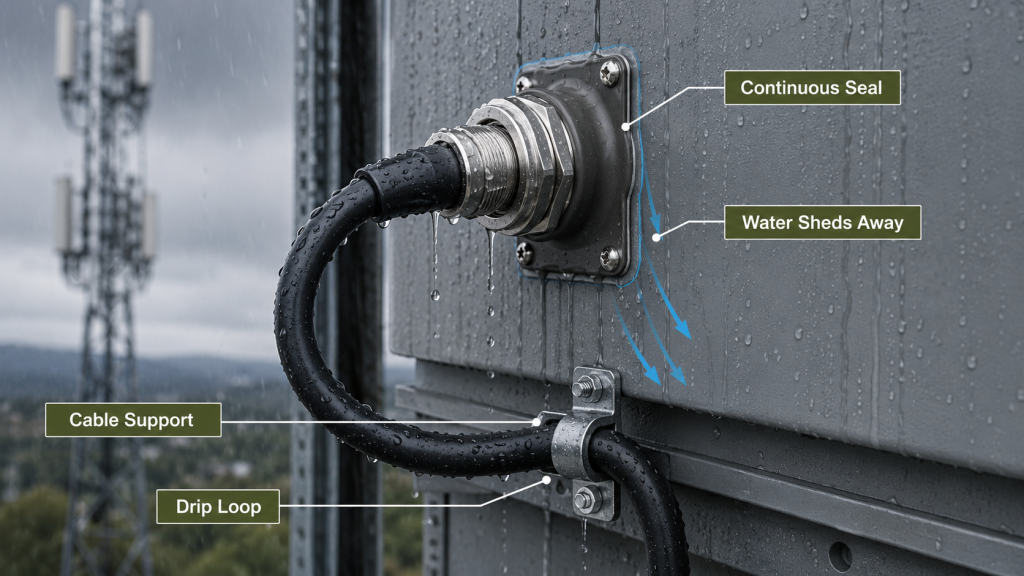
The final assembly has three separate jobs. The mating interface maintains the RF connection. The external weatherproof layer limits moisture entry. Cable support and strain relief keep movement from opening the joint again.
A drip loop adds another control by directing water below the connection before the cable rises toward the connector. It does not replace the seal, and the seal does not replace a drip loop or mechanical support.
Do not use extra coupling torque as a sealing method unless the connector procedure explicitly calls for it. Excess torque can damage threads, gaskets, dielectric geometry, panel mounting, or contact alignment.
4. How Condensation, Routing, and Maintenance Reopen the Moisture Path
Rain is only one source of moisture. Condensation can form when humid air is trapped inside a joint or cabinet and the hardware cools below the local dew point. Repeated thermal cycling can also move air and moisture through small gaps that are difficult to see during a dry inspection.
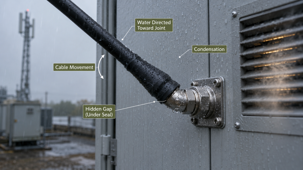
Routing can make the same problem worse. Risk increases when a cable slopes toward the connector, water sits at the edge of the seal, a heavy feeder pulls sideways on the mating interface, the first bend starts directly behind the connector, or vibration repeatedly loads the same point.
Maintenance is another common reopening event. A joint that was dry before service can become vulnerable if the original seal is cut away and not rebuilt to the same boundary, if a gasket is displaced, if contamination is introduced, or if the cable is re-routed so that water now drains toward the connection.
Record weather and maintenance timing when the fault is intermittent. Useful fields include rain start/stop time, humidity, ambient temperature, morning condensation, connector service date, resealing date, drying time, alarm timestamp, affected branch, and the available FWD/REV or VSWR data.
If the fault follows antenna alignment, cable support, warm-up, or reassembly rather than weather exposure, check the RF PA antenna feed interface before treating it as a sealing problem.
5. How to Isolate a Weather-Linked VSWR or Reflected-Power Fault
A weather-linked alarm narrows the investigation, but it still does not identify the failed component. Preserve the failing condition before several parts are changed at once.
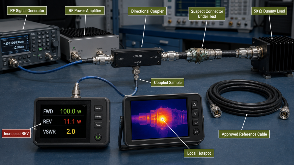
Use a controlled sequence:
- Record the original frequency, RF input or control target, forward power, reflected power or VSWR, DC condition, thermal state, alarm/protection state, and the measurement reference plane.
- Inspect the exposed connector, cable transition, feedthrough, sealing layer, and nearby cabinet entry for water, corrosion, staining, damaged dielectric, plating loss, loose hardware, or trapped moisture.
- Establish a controlled baseline before changing field hardware. A dummy-load versus installed-path comparison can show whether the PA behaves normally before the feeder, connector, and antenna path are reintroduced.
- Change one path section at a time. Keep the relevant frequency, drive rule, DC supply, load, correction settings, and thermal starting condition as comparable as practical.
- Begin the repaired-path check at low RF power. Increase power only after the connector and cable condition are safe for the required test.
- Repeat the observation after the joint is rebuilt, mechanically supported, and resealed.
A fault that follows one wet or damaged section under controlled comparison supports an external path cause. It does not prove the exact internal failure mechanism until the suspect section is inspected or replaced and the result is repeated.
Stop high-power testing when inspection finds severe corrosion, pitting, burned contact surfaces, cracked or swollen dielectric, damaged threads, an unstable connector body, water inside the cable, or other damage that makes the connection unsafe or non-repeatable.
6. When to Repair, Replace, and Retest the Connector or Cable Assembly
Drying can remove moisture without reversing material damage. The decision after a wet joint is therefore repair versus replacement, followed by a controlled retest.
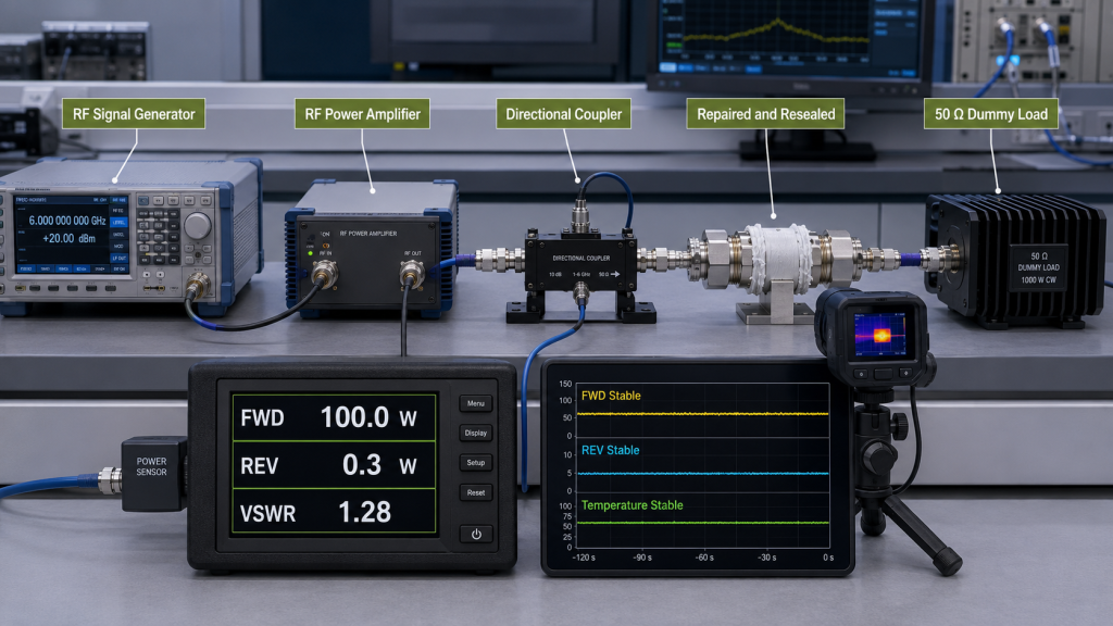
Reuse or approved rework is reasonable only when the service procedure permits it and the parts that define the RF transition remain serviceable. Check the center contact, plating, dielectric, threads, shield termination, cable interior, connector body, gasket, and sealing surfaces.
Replace or formally rework the affected connector or cable assembly when you find:
- corrosion or pitting on contact surfaces;
- burned or badly discolored contact areas;
- cracked, swollen, displaced, or contaminated dielectric that cannot be restored by the approved procedure;
- damaged threads or unstable seating;
- water migration inside the cable;
- a loose or damaged connector body;
- repeatable RF instability that follows the suspect termination after controlled substitution.
After repair, use the same engineering boundary that matters for acceptance. Record the required frequency points, RF input or control rule, forward and reflected behavior, VSWR or return loss where applicable, cable routing, load condition, DC state, thermal condition, connector temperature if relevant, test duration, and protection state.
Compare the original fault condition, the dry condition before repair when it can be captured safely, the repaired/resealed condition, and the required hot-state or outdoor-condition retest. A joint that passes immediately after service may still fail after thermal cycling or environmental exposure.
The repaired path is acceptable only when the defined RF result is stable and the final mechanical and weatherproof boundary is the same one that will remain in service.
7. What Sealing and Post-Repair Evidence Belongs in RFQ and Acceptance
A statement such as “waterproof connector” is too broad for an RFQ. The requirement should identify the installed condition that must stay dry and the evidence needed after installation or maintenance. Any environmental or ingress rating should also state the tested connector condition, such as mated, capped, panel-mounted, or assembled with the final cable, because a component rating cannot automatically be extended to a different installed configuration.
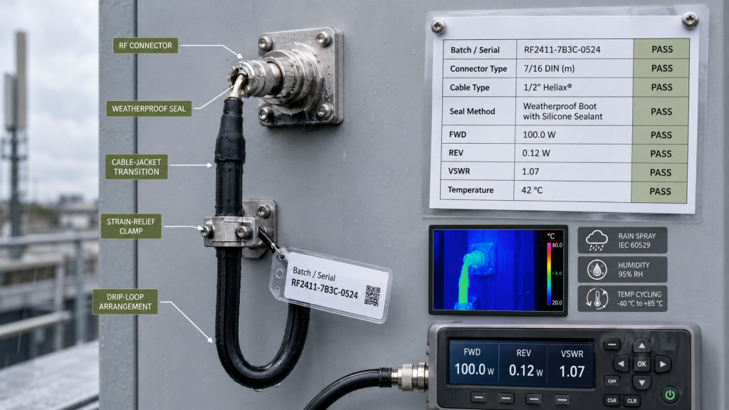
| RFQ / acceptance item | Evidence to define |
|---|---|
| Connector and mating interface | Connector types, mating condition, gasket/O-ring requirement, approved assembly procedure |
| Cable transition | Cable type, termination method, rear-body sealing boundary, strain relief |
| Outdoor exposure | Rain/spray, humidity, temperature range, UV, salt-fog or other project-specific conditions |
| Routing and drainage | Connector orientation, cable support, bend radius, drip-loop arrangement, cabinet entry |
| Maintenance | How the seal is removed, inspected, rebuilt, and recorded after service |
| RF verification | Frequency points, measurement reference plane, FWD/REV or VSWR boundary, RF power/duty condition, thermal state, test duration |
| Repair acceptance | Replacement criteria, post-repair comparison, alarm/protection result, final resealed condition |
| Traceability | PA/channel identity, cable/connector identity, service date, final path or S/N linkage where required |
For a project using RF SKYPOWER RF power amplifier modules, the engineering review should receive the frequency range, target RF output, connector and cable interface, feeder layout, environmental exposure, sealing method, mismatch boundary, and required post-repair evidence before the outdoor interface is finalized.
That information is enough to review the PA-side interface and acceptance boundary. It does not establish that a particular module is suitable until the project-specific electrical, thermal, mechanical, control, and RF requirements have been checked.
After repair, release the joint only when the identified, supported, sealed connection remains within the defined RF limits under the environmental and operating conditions required by the project.
For an interface or RFQ review, contact RF SKYPOWER engineering with the same boundary data.