










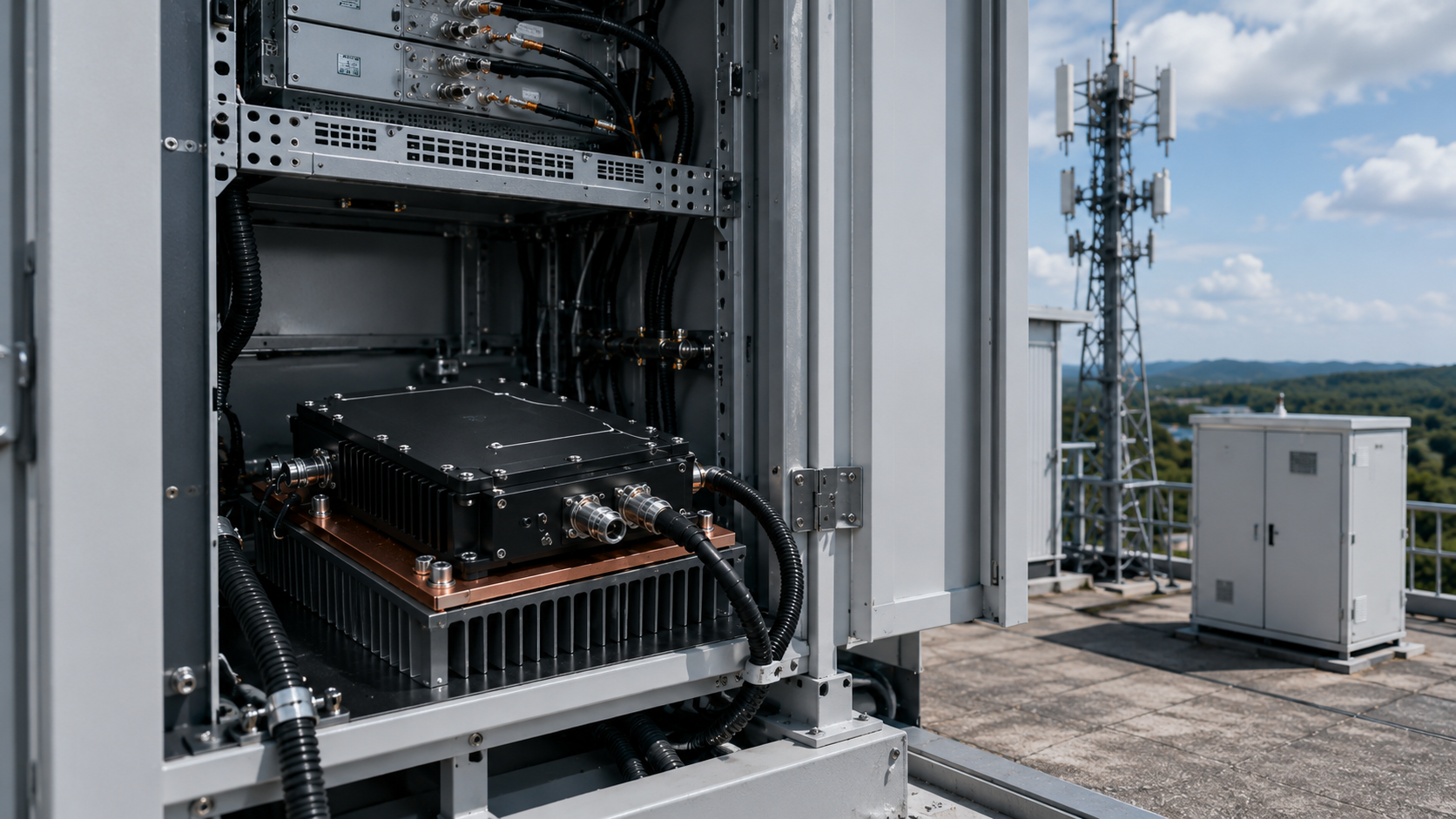
Prevent RF PA fastener failure by defining what each joint must hold, checking the screw and hole geometry before assembly, and using a controlled tightening and retention process suited to the installed environment. A wrench reaching its target torque does not establish that the parts were clamped: the screw may have bottomed in a blind hole, the threads may be damaged, or friction may have consumed much of the applied torque.
Start with the joint’s function. A baseplate screw, shield-cover screw, and RF connector bracket can have similar hardware but very different failure consequences. Their drawings and inspection criteria should reflect those differences.
1. Define What Each Joint Must Hold
Mark the critical fasteners on the assembly drawing. Record which parts each screw clamps and what must remain stable after installation, transport, operation, and service. For each joint, define the failure boundary: separation, slip, rotation, loss of thermal or conductive contact, or connector movement beyond its alignment limit.
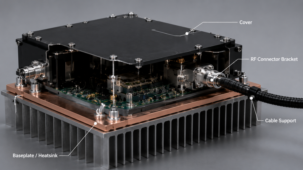
| Joint | Condition the fastener must maintain | What movement can change |
|---|---|---|
| PA baseplate to heatsink | Seating and pressure across the specified thermal interface | Local contact and temperature |
| Shield cover or chassis bond | Specified mechanical seating and conductive contact | Shielding or bonding condition |
| RF connector bracket | Connector position without cable side load | Alignment or RF-interface contact |
| Cable support or cabinet mount | Restraint and assembly position | Load at the connector, fatigue, or module alignment |
Use the joint-specific drawing or assembly procedure to set clamp and torque requirements for each location. For a thermal joint, the fastener controls part of the contact condition; the RF PA heatsink design review covers the spreader, thermal-interface material, heatsink, and airflow as a complete heat path.
2. Check RF PA Screw Grip, Blind-Hole Depth, and Thread Engagement
Confirm the installed stack before selecting screw length. Include the bracket or baseplate thickness, washers, any specified interface layer, and the depth of usable mating threads. In a blind hole, the drawing must leave clearance between the screw tip and the bottom when the head has seated the joint.
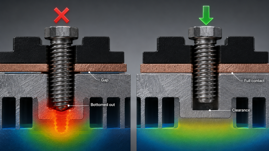
Check the screw diameter, pitch, material, finish, and intended engagement against the drawing and the actual mating thread or insert. Do not count the drilled tip or an incomplete thread as usable engagement. Inspect tapped aluminum, inserts, and screw threads for damage before final assembly.
A bottomed screw can resist the tool while leaving the clamped parts loose. A partially stripped thread can also give a misleading reading or lose load after installation. Stop assembly if either condition appears. Correct the length, hole, or thread under the specified repair process; increasing torque cannot restore a missing load path.
There is no universal engagement length for every PA housing. The required value depends on the mating material, insert, joint geometry, expected load, and service-removal cycle.
3. Apply Clamp Load Without Distorting the PA
Torque is an assembly control; clamp load is the result the joint needs. Thread and bearing-surface friction affect the relationship between them. A change in screw finish, washer, lubricant, or threadlocker can change preload even when the wrench shows the same number.
With a prevailing-torque nut, locking patch, or self-locking insert, the assembly instruction should define how running torque is measured and treated. The tool’s total reading includes resistance from the locking feature; that portion does not create clamp load. NASA’s Fastener Design Manual gives general engineering context for friction, locking torque, and temperature effects. Set RF PA acceptance from the joint-specific drawing and operating limits.
Seat the joint on clean, specified mating surfaces. Start all screws before taking any one fastener to final torque. Follow the tightening stages and sequence specified for that assembly, using a calibrated tool in its applicable range. Record the controlled process when the drawing or acceptance plan requires it. A cross pattern may be appropriate for some baseplates, but it should come from the assembly instruction rather than a generic rule.
Too little clamp can let a thermal interface open or a bracket slip. Too much can damage threads or inserts and distort a baseplate. Do not copy a torque value from another screw size or housing. If the thermal result depends on grease or another interface material, use its specified application and compression method; extra torque is not a substitute for controlling the RF PA thermal interface.
4. Maintain RF PA Joint Clamp Through Heat, Vibration, and Service
A correctly preloaded joint resists relative movement. A locking feature adds retention when the operating or maintenance condition calls for it; it does not repair bottoming, damaged threads, or inadequate clamp.
Thermal cycling can raise or lower clamp load without visible screw rotation when a steel screw and a stack containing aluminum, copper, or heatsink materials expand differently. Review the joint across the required temperature range; witness marks alone cannot reveal this load change.
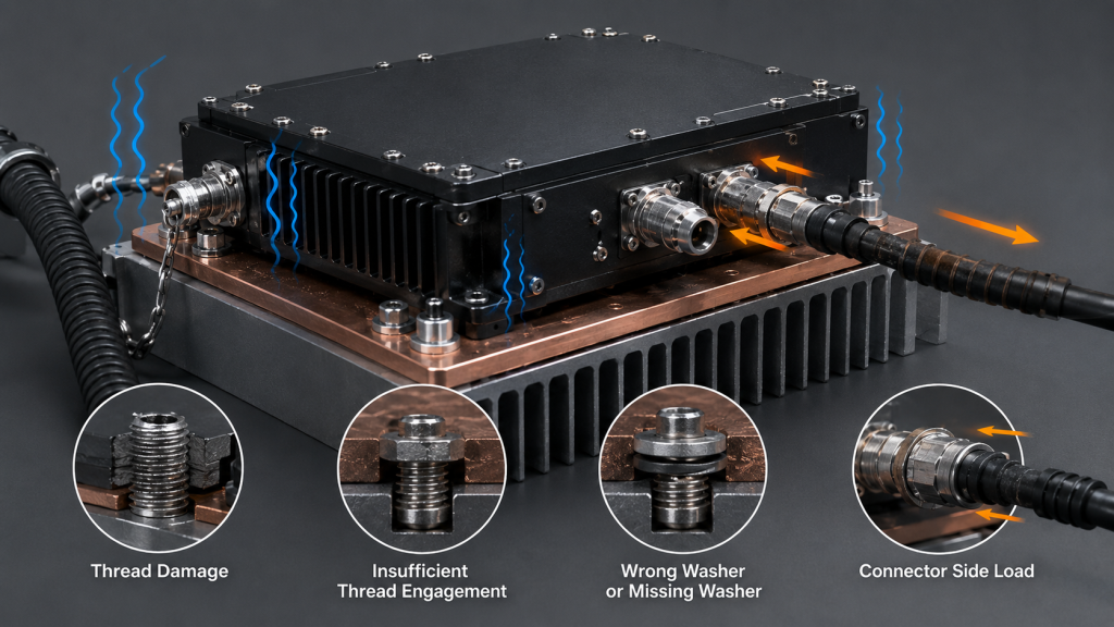
Choose a locking method specified for the joint temperature, vibration or shock exposure, materials, and removal plan. Threadlocker requires a specified product, surface preparation, cure, and service procedure. Keep it off RF contacts, thermal mating surfaces, and conductive bond faces. A prevailing-torque feature or mechanical lock can help keep a fastener from backing out after preload falls. Check clamp-load stability separately. Account for every washer or locking part in the installed stack and bearing-surface design.
Support heavy or moving RF cables so their bending load does not reach the connector bracket. After service, replace single-use locking parts or reapply threadlocker as specified, then restore the defined tightening sequence. If a joint needed retightening, investigate the original loss of load.
5. Protect Mixed-Metal Contacts
Moisture at a joint containing dissimilar metals can damage a finish, seize a thread, or change clamping and electrical contact conditions. Review the actual stack: screw, washer, insert, housing, spreader, finish, and the path by which water or condensation could reach them.
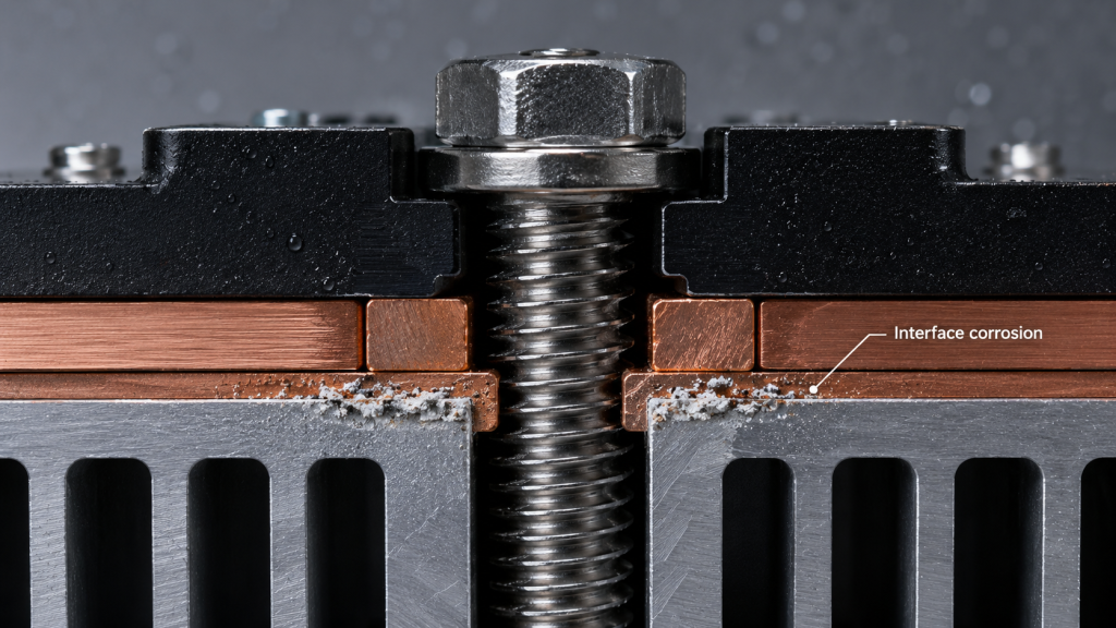
Specify materials and surface protection for the expected environment and maintenance interval. A coating or insulating washer that helps one corrosion boundary may be unsuitable at a joint required to provide conductive bonding. Resolve that tradeoff in the joint design and verify the resulting contact, rather than adding a generic washer at assembly.
Treat discoloration as an inspection prompt. Check whether corrosion has affected the thread, bearing face, contact surface, clamp condition, or ability to disassemble and reassemble the joint. A corroded or seized fastener needs a documented disposition before reuse.
6. Inspect a Suspect Joint and Decide on Rework
After heat cycling, vibration, transport, or maintenance, look for a shifted bracket, changed witness mark, cover gap, damaged thread, corrosion, or a cable pulling the connector off its intended alignment. Temperature rise or an intermittent RF symptom can make a joint worth inspecting, but neither symptom identifies a fastener as the cause by itself.
First compare the hardware with the joint-specific drawing and the pre-exposure condition. Check seating, screw length and hole clearance where accessible, thread or insert damage, washers, locking features, cable support, and the relevant bond or thermal interface. A witness mark can reveal rotation; an unchanged mark cannot prove the original preload was correct.
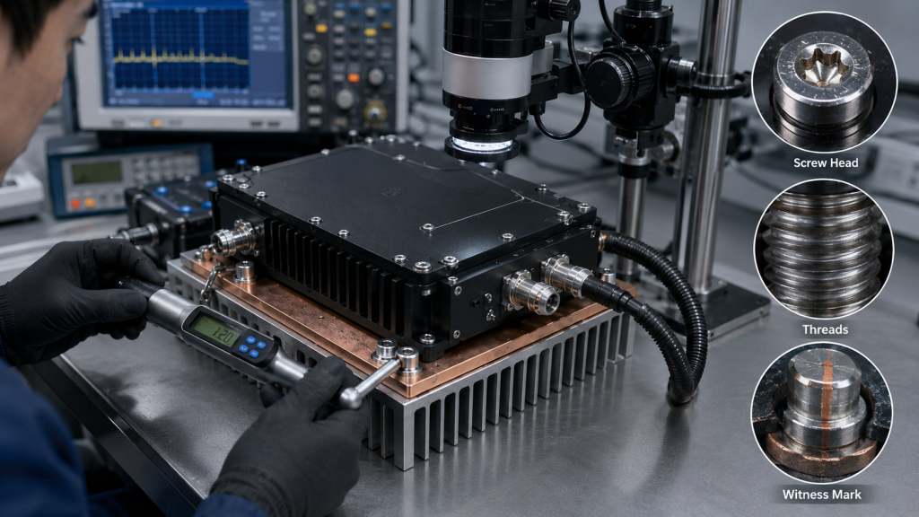
If the load path, thread, insert, or contact condition is uncertain, stop and inspect or disassemble under the documented procedure. Rework the defect, restore the specified joint stack and tightening process, and repeat the checks relevant to that joint. Do not use a quick retorque to erase an unexplained fault.
When RF or thermal readings are part of the comparison, keep the decision-relevant frequency, drive, load, DC supply, duty cycle, cooling condition, measurement point, and test duration aligned. Local fastener inspection cannot establish post-vibration RF performance; that separate decision needs a defined exposure and comparable RF measurements, as the RF PA vibration test guide explains.
7. Define the Fastener Boundary Before Integration
Before ordering or assembling a PA, put the joint requirements into the applicable drawing or RFQ. Identify each critical fastener’s location and function, the installed stack and mating material, the screw and insert specification, usable hole depth, required engagement and clearance, tightening process, locking method, environmental exposure, service cycle, and inspection or rework rule. Define which local checks are required after the project’s relevant thermal or mechanical exposure.
Where a new module or mounting arrangement is being considered, the RF power amplifier module family is a configuration starting point. Confirm the selected module’s baseplate, bracket, heatsink, and fastener joints against the applicable drawing and assembly evidence.
Conclusion
Approve a fastener joint only after its function, geometry, clamp process, retention method, and relevant service condition agree with the project drawing. Use geometry, seating, and service checks alongside torque records and witness marks.
Before approving the joint, compare the actual hardware with the drawing and resolve any bottoming, thread damage, uneven seating, movement, or corrosion through the documented repair and retest process. If the mounting interface needs supplier review, send RF SKYPOWER’s engineering team the module and mating drawings, joint stack, materials, operating environment, tightening method, and required inspection evidence.