


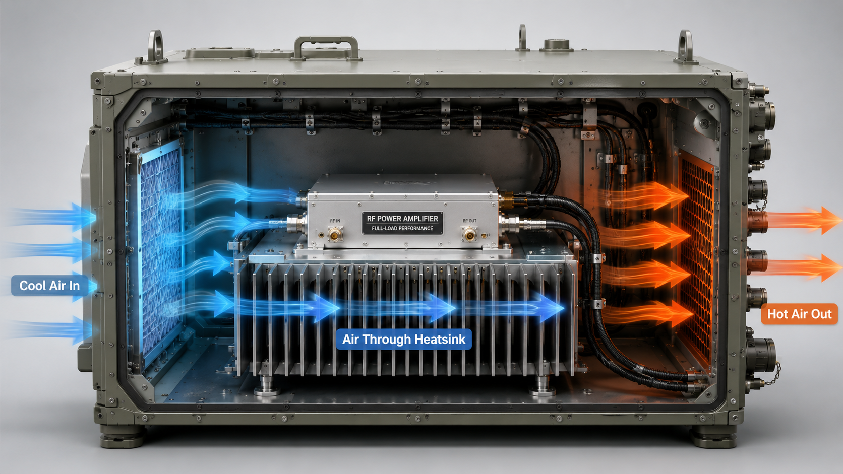
Cabinet airflow affects RF Power Amplifier full-load performance because heat must leave the heatsink, not just move inside the enclosure. In a C-UAS cabinet, vehicle-mounted RF box, or fixed-site perimeter system, an amplifier module may pass open-bench testing but run hotter after installation because the cabinet adds airflow resistance, cable blockage, filter pressure drop, and heat recirculation. This is why RF Power Amplifier Cabinet Airflow should be treated as part of the system boundary, not as a fan accessory topic.
The real question is not whether the fan looks large. The real question is whether air passes through the heatsink, removes heat from the module area, and exits the cabinet without being pulled back into the inlet. For system integrators, that difference can decide whether a high-power RF module maintains stable long-duty output or triggers temperature protection during real operation.
1.What Does Cabinet Airflow Mean for RF Power Amplifier Modules?
Cabinet airflow means the controlled path that carries heat away from RF Power Amplifier modules after heat reaches the heatsink. RF Power Amplifier Cabinet Airflow includes inlet position, outlet position, fan direction, heatsink fin orientation, module spacing, cable routing, filter resistance, and whether hot air is separated from cold intake air.
Here’s the engineering point: airflow is not the same as “air movement.” A fan can create visible air movement while still failing to move air through the thermal path that matters.
How does heat travel before air removes it?
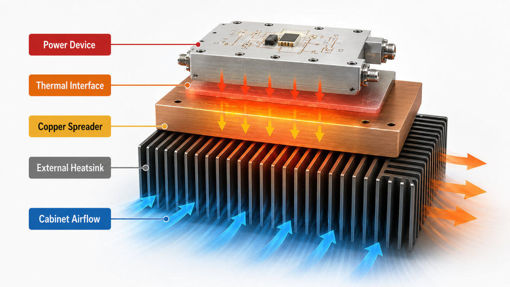
Heat usually moves from the RF power device into the module structure, then into an external heatsink or chassis surface before air removes it. If one step in this chain is weak, the next step cannot fully correct it.
Key heat path elements include:
- Power device junction and package
- Thermal interface layer
- Copper spreader or module base
- External heatsink or chassis wall
- Forced airflow through the cabinet
The practical risk is clear: you may test a module on a bench with good open airflow, then see higher temperature after the same module is installed inside a closed cabinet.
What should engineers check first?
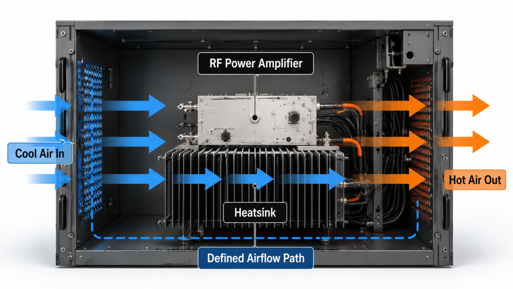
Engineers should first check whether air actually passes through the heatsink area, not just near the module. The airflow path should be visible as a route from inlet to outlet.
Typical first checks include:
- Is the inlet blocked by a filter, door, or cable bundle?
- Is the outlet large enough for exhaust air?
- Are heatsink fins aligned with the airflow direction?
- Can hot air escape without looping back?
- Do nearby modules share the same hot air path?
Key Takeaway: Cabinet airflow helps you judge whether the module’s thermal path can keep working after the heat reaches the heatsink. Without a defined air path, even a well-designed RF module can become limited by the enclosure.
| Airflow Element | What It Controls | Integration Risk |
|---|---|---|
| Inlet | Cold air access | Module receives warm or restricted air |
| Heatsink path | Heat transfer to air | Fins do not receive useful airflow |
| Outlet | Hot air removal | Cabinet temperature rises |
| Module spacing | Local heat buildup | One module heats another |
| Cable routing | Flow obstruction | Air bypasses the heatsink |
This table gives you a simple way to separate module heat design from cabinet-level airflow conditions.
2.Why Can’t Fan Size Define RF Power Amplifier Cooling?
Fan size cannot define RF Power Amplifier cooling because mechanical diameter does not prove usable airflow through the cabinet. RF Power Amplifier Cabinet Airflow depends on resistance, pressure, inlet design, outlet design, and whether the air reaches the heatsink surface.
A large fan can still perform poorly if it blows against a closed path. This is where system integrators should pay attention: a fan datasheet often describes performance in open or low-resistance conditions, while a real RF cabinet is full of restrictions.
Why does a large fan sometimes fail in a cabinet?
A large fan can fail because the cabinet does not allow the rated airflow to pass through the required path. The fan may move air near the inlet while the heatsink area receives only weak flow.
Common causes include:
- Small outlet openings
- Dense heatsink fins
- Dust filters with high pressure drop
- Cable bundles across the main path
- Fan blowing at the cabinet wall instead of through fins
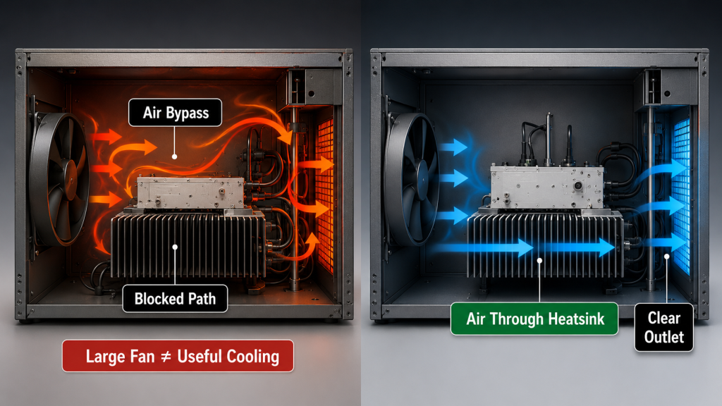
Here’s the field reality: if the air has no low-resistance path to exit, the fan may simply stir warm air inside the enclosure.
What does useful airflow look like?
Useful airflow enters from a cooler zone, crosses the heat source, and exits before it mixes back into the intake area. It should support the real module layout, not only the fan mounting position.
Useful airflow should show:
- Cold intake separated from hot exhaust
- Air crossing the heatsink face or fins
- Minimal blockage from harnesses
- Enough outlet area
- No obvious recirculation loop
Key Takeaway: Fan size is only a mechanical clue. Real cooling performance depends on whether air reaches the heatsink, absorbs heat, and leaves the cabinet.
| Fan Assumption | Real Engineering Question | Better Check |
|---|---|---|
| Fan is large | Does air reach the heatsink? | Smoke test or airflow mapping |
| Fan RPM is high | Is pressure enough under restriction? | Static pressure curve |
| Air is moving | Is hot air leaving the cabinet? | Intake and exhaust temperature |
| Fan is near module | Is flow direction correct? | Fin orientation check |
| Fan feels strong | Does the far module receive air? | Multi-point temperature test |
This comparison keeps the discussion focused on RF system cooling, not fan appearance.
3.How Does Airflow Remove Heat After the Heatsink Works?
Airflow removes heat by carrying thermal energy away from the heatsink surface and out of the cabinet. RF Power Amplifier Cabinet Airflow becomes the next limiting factor after the device, thermal interface, copper structure, and external heatsink have already moved heat away from the active components.
A heatsink is not where heat disappears. It is a transfer structure between the RF module and the surrounding air, which is why cabinet airflow must support the heatsink instead of being treated as a separate accessory.
Why is the heatsink only part of the answer?
The heatsink spreads heat across a larger surface area, but it still needs air to remove that heat. If air does not move across the fins, the heatsink temperature rises until the module reaches a higher operating temperature.
Important heat transfer points include:
- A larger heatsink helps only if airflow reaches it
- Fin spacing must match airflow capability
- Heat must be exhausted, not trapped nearby
- Long-duty operation depends on continuous heat removal
The practical risk is clear: a strong heatsink can look correct mechanically while failing thermally inside a restricted cabinet.
What happens when air does not carry heat away?
When air cannot carry heat away, the heatsink becomes a heat reservoir. The module may operate normally at first, then slowly approach a temperature limit during long-duty operation.
You may see:
- Gradual shell temperature rise
- Output power drift or reduction
- Temperature alarm activation
- Higher internal cabinet temperature
- Different results between open bench and closed cabinet
Key Takeaway: The heatsink spreads heat, but airflow removes it from the system. Your cabinet design decides whether the heatsink can keep working under full RF load.
| Thermal Stage | Main Function | Failure If Unsupported |
|---|---|---|
| Power device | Generates RF power and heat | Junction temperature rises |
| Thermal interface | Transfers heat to structure | Local hotspot forms |
| Copper spreader | Spreads heat laterally | Heat concentrates near device |
| External heatsink | Expands surface area | Heat accumulates in fins |
| Cabinet airflow | Removes heat from cabinet | Full-load temperature rises |
This sequence helps you locate the real bottleneck instead of blaming the wrong component.
4.Why Does Static Pressure Matter inside RF Cabinets?
Static pressure matters because it decides whether airflow can pass through the resistance created by heatsinks, filters, cables, openings, and compact module layouts. RF Power Amplifier Cabinet Airflow cannot be judged only by free-air fan volume because real cabinets create pressure drop.
Airflow ratings often look strong in ideal conditions. Here’s the engineering point: once the fan faces dense fins, dust filters, narrow vents, and blocked outlets, actual airflow can fall sharply.
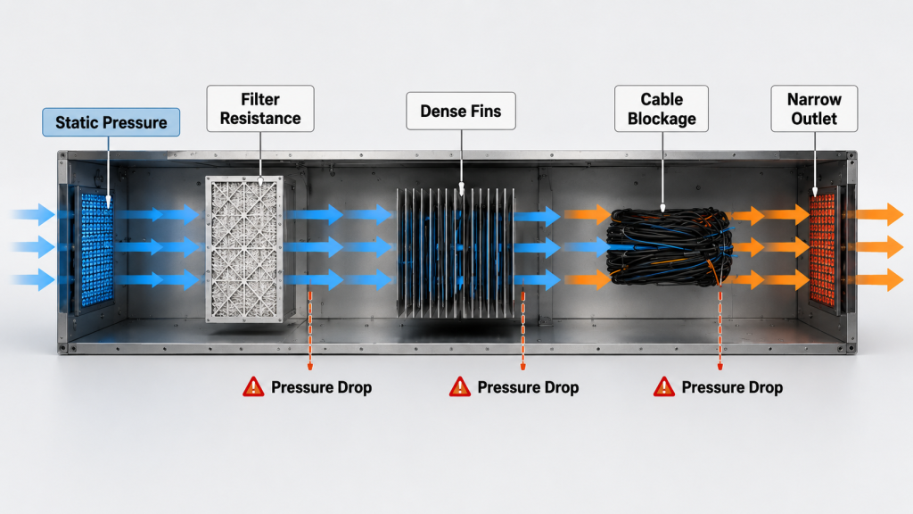
What creates resistance in a real cabinet?
Resistance appears anywhere air must squeeze, turn, pass through material, or move around obstacles. RF cabinets often contain many of these restrictions at the same time.
Common airflow resistance sources include:
- Dense heatsink fins
- Dust filters and mesh screens
- Narrow vent holes
- Sharp airflow turns
- Harnesses and RF cables
- Power supplies and control boards
- Closely stacked RF modules
This is where system integrators should pay attention: the fan must be matched to the cabinet load, not only to the module power level.
How can weak static pressure affect RF modules?
Weak static pressure can reduce actual airflow through the heatsink even when the fan is spinning at high speed. The result is not always immediate failure; it often appears as gradual thermal rise during longer operation.
Likely effects include:
- Lower airflow through fin channels
- Uneven cooling across multiple modules
- Hot zones near rear cabinet corners
- More frequent temperature protection
- Higher noise from fans working inefficiently
Key Takeaway: Static pressure is what makes airflow useful inside a restricted cabinet. Without enough pressure capability, rated fan volume may not translate into real cooling.
| Cabinet Restriction | Effect on Airflow | Engineering Response |
|---|---|---|
| Dense fins | Higher pressure drop | Match fan pressure curve |
| Filter | Reduced intake flow | Check clogged and clean states |
| Small outlet | Exhaust backpressure | Increase vent area |
| Cable bundle | Local blockage | Re-route harnesses |
| Tight module spacing | Uneven cooling | Add spacing or ducting |
This table shows why cabinet airflow should be reviewed with mechanical layout, not only with electrical load.
5.How Can Cabinet Resistance Make Bench Tests Misleading?
Cabinet resistance can make bench tests misleading because open-air testing removes the restrictions that appear after installation. RF Power Amplifier Cabinet Airflow may look sufficient during bench testing, while the final cabinet layout creates higher temperature under the same RF output.
An RF module may cool well on an open bench because heat escapes freely. In a vehicle-mounted or fixed-site C-UAS platform, the same module may sit near other heat sources, behind a filter, under a cable bundle, or inside a narrow exhaust path. In low-altitude security and C-UAS systems, multiple RF channels may also share one enclosure, so airflow must support the complete RF chain.
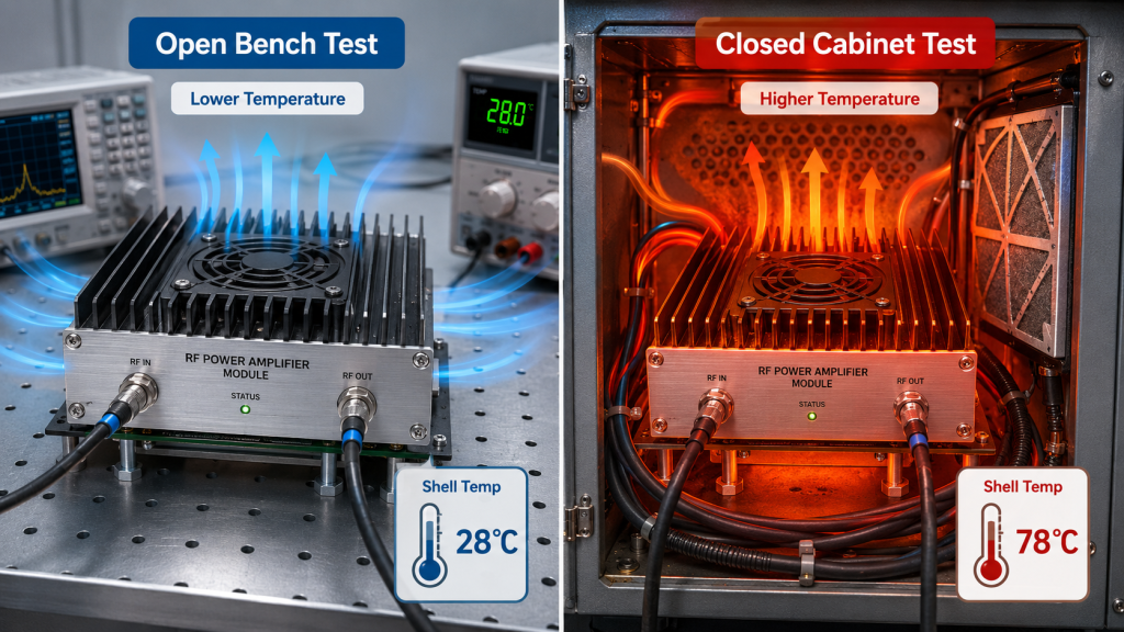
Why does open-bench cooling look better?
Open-bench cooling looks better because the module has fewer airflow restrictions and more free convection around it. The heatsink can release heat into the surrounding air without competing with other cabinet components.
Open-bench advantages include:
- No closed-door temperature rise
- Less inlet restriction
- No shared hot exhaust
- Easy heat escape from all sides
- More space around the heatsink
Here’s the field reality: a clean bench test is useful, but it does not prove cabinet thermal behavior.
What changes after cabinet installation?
Cabinet installation changes the air path, local ambient temperature, and interaction between modules. These changes can turn a stable bench result into a borderline field result.
Typical installation changes include:
- Door closed during operation
- Filter installed at the intake
- RF cables blocking local airflow
- DC power supply adding heat
- Several modules operating together
- Hot exhaust trapped near the rear panel
Key Takeaway: Bench testing proves module behavior under a controlled condition, while cabinet testing proves system behavior under the real installation boundary.
| Test Condition | What It Proves | What It May Miss |
|---|---|---|
| Open bench | Basic module operation | Cabinet resistance |
| Fan near module | Local cooling response | Real inlet and outlet path |
| Single module | Individual heat behavior | Multi-module heat coupling |
| Short RF test | Initial stability | Long-duty heat buildup |
| Cabinet closed test | Real integration behavior | Requires better setup control |
This comparison helps you decide when a passing bench result is not enough for approval.
6.Why Does Heat Recirculation Raise RF Amplifier Temperature?
Heat recirculation raises RF amplifier temperature because the fan pulls warm exhaust air back into the intake side. RF Power Amplifier Cabinet Airflow must separate cold intake from hot exhaust, or the module will keep cooling itself with air that is already heated.
This problem can be hard to notice because the fan is still spinning and air is still moving. Here’s the engineering point: cooling requires directed airflow, not random air movement.
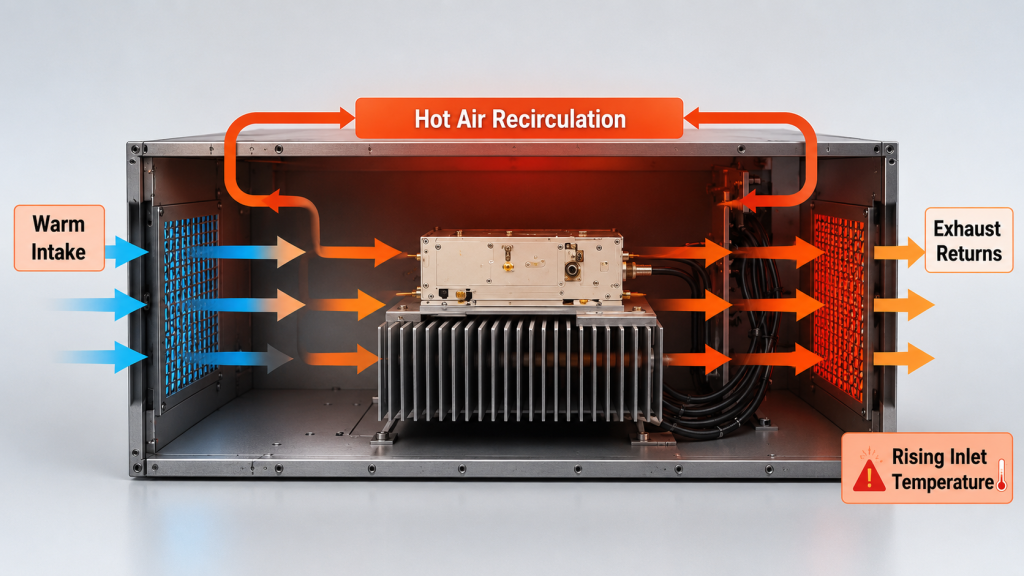
Where does recirculation usually happen?
Recirculation usually happens near poor inlet-outlet placement, blocked exhaust routes, or fan layouts that fight each other. It can also happen when one module’s exhaust becomes another module’s intake.
Common recirculation points include:
- Intake and exhaust openings placed too close
- Fan installed in the wrong direction
- Rear exhaust blocked by a wall or panel
- Internal baffles reflecting hot air
- Modules stacked in the same hot airflow path
- No separation between hot and cold zones
The practical risk is clear: a system can appear ventilated while the module inlet temperature keeps rising.
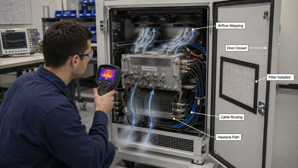
How can engineers identify hot-air loops?
Engineers can identify hot-air loops by comparing intake air temperature, exhaust temperature, cabinet internal temperature, and module shell temperature during load. A thermal camera can also make recirculation visible.
Useful checks include:
- Measure inlet temperature near each module
- Measure exhaust temperature near each outlet
- Run the test with cabinet door closed
- Check fan direction physically
- Watch for rising intake temperature over time
- Compare front module and rear module temperatures
Key Takeaway: Hot-air recirculation turns airflow into a closed heat loop. If exhaust air returns to the intake, fan movement cannot guarantee cooling.
| Recirculation Cause | Symptom | Correction Direction |
|---|---|---|
| Inlet near outlet | Intake air warms quickly | Separate openings |
| Wrong fan direction | Heat trapped inside | Verify airflow direction |
| Blocked exhaust | Cabinet temperature rises | Open exhaust path |
| Module-to-module heating | Rear module runs hotter | Reorder layout or duct air |
| Poor baffle design | Local hot pocket | Guide air across heatsink |
This table turns an invisible airflow problem into practical inspection points.
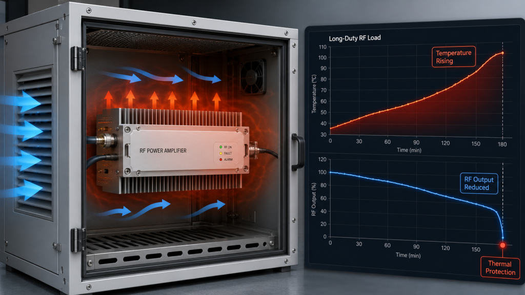
7.How Does Poor Airflow Affect Long-Duty RF Output?
Poor airflow affects long-duty RF output by allowing heat to accumulate faster than the cabinet can remove it. RF Power Amplifier Cabinet Airflow becomes especially important when the module must support continuous or repeated high-power operation inside a closed system.
Short tests may not reveal the problem because the heatsink and chassis still have thermal capacity. This is where system integrators should pay attention: long-duty operation exposes airflow limits that a short acceptance test may hide.
Why do short tests hide airflow problems?
Short tests hide airflow problems because heat has not reached steady-state conditions. The module may look stable for several minutes, while cabinet temperature continues rising over a longer period.
Short-test blind spots include:
- Slow heatsink temperature rise
- Cabinet ambient temperature buildup
- Filter pressure effects
- Multi-module heat coupling
- Fan performance after warm-up
- Protection behavior under sustained load
Here’s the field reality: long-duty RF operation is a system test, not only a module test.
What symptoms appear during extended operation?
Extended operation can show symptoms that do not appear during initial power-on. These symptoms often look like module weakness unless airflow is checked.
Possible symptoms include:
- Gradual output reduction
- Temperature alarm activation
- Thermal protection or shutdown
- Higher module shell temperature
- Fan speed staying at maximum
- Different performance after cabinet door closes
Key Takeaway: Long-duty RF output depends on continuous heat removal. Temperature protection can protect the module, but it cannot replace correct cabinet airflow.
| Long-Duty Symptom | Possible Airflow Cause | What to Check |
|---|---|---|
| Output drops over time | Heat buildup | Shell and heatsink temperature |
| Thermal alarm | Restricted airflow | Intake and exhaust path |
| Rear module hotter | Shared hot air | Module placement |
| Fan always at high speed | High cabinet resistance | Static pressure and vents |
| Door-open test passes | Closed cabinet restriction | Repeat test with door closed |
8.How Should Engineers Evaluate RF Cabinet Airflow?
Engineers should evaluate RF cabinet airflow under real layout, real RF load, and closed-cabinet conditions. RF Power Amplifier Cabinet Airflow should be reviewed as part of integration, not after temperature alarms appear.
A useful airflow review asks where air enters, what it cools, what blocks it, and where it exits. The question is not “is there a fan?” The question is “does the airflow path support the RF power level and duty profile?”
What layout checks should come first?
Layout checks should confirm that the airflow path matches the heatsink and module arrangement. If air bypasses the heatsink, airflow capacity on paper does not matter much.
Start with these checks:
- Air enters from a cool source
- Air crosses the heatsink fins
- Fin direction matches fan direction
- Outlet is not smaller than the inlet path needs
- Cable routing avoids the main air channel
- Modules have enough spacing for airflow
Here’s the engineering point: airflow should be inspected in the same mechanical layout that will ship.
What test conditions should match the field?
Test conditions should match the cabinet’s real working state as closely as possible. A test without the door, filter, harness, or nearby modules can miss the real airflow limit.
Field-like test conditions include:
- Cabinet door closed
- Filters installed
- Normal cable routing used
- Multiple RF modules operating if applicable
- Expected DC supply and load condition
- Ambient temperature recorded
- Run time long enough to see stabilization
Key Takeaway: Airflow evaluation should be performed in the final cabinet layout. A fan datasheet cannot replace a closed-cabinet RF load test.
| Evaluation Area | Question to Ask | Good Sign |
|---|---|---|
| Intake | Is air cool and unrestricted? | Low inlet temperature |
| Heatsink | Does air cross the fins? | Even fin temperature |
| Exhaust | Can hot air leave? | Stable cabinet temperature |
| Layout | Are cables blocking flow? | Clear main path |
| Test setup | Does it match field use? | Door-closed load data |
This table gives engineers a basic airflow review structure before final integration approval.
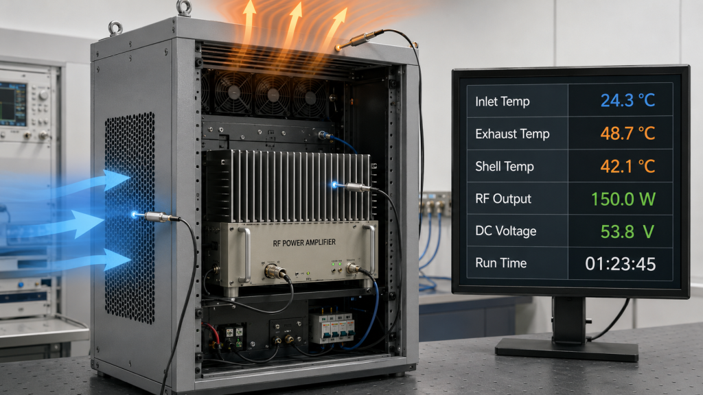
9.What Data Should Cabinet Airflow Testing Record?
Cabinet airflow testing should record thermal, electrical, airflow, and operating-condition data under real RF load. RF Power Amplifier Cabinet Airflow cannot be judged confidently from a single temperature reading because the issue may come from inlet restriction, exhaust blockage, static pressure loss, or hot-air recirculation.
Good data helps you separate module thermal limits from system airflow limits. In airport or perimeter installations, for example, cabinet environment and maintenance workflow can become part of deployment reliability, as shown in airport counter-UAS integration scenarios.
Which thermal data matters most?
Thermal data should show both module temperature and air temperature around the cooling path. This makes it easier to locate whether heat is trapped at the heatsink, inside the cabinet, or at the inlet.
Useful thermal data includes:
- Ambient room temperature
- Cabinet internal temperature
- Module shell temperature
- Heatsink inlet temperature
- Heatsink exhaust temperature
- Temperature alarm status
- Run time at each power level
This is where system integrators should pay attention: a shell temperature alone does not explain why the shell is hot.
Which operating data should be recorded?
Operating data should connect the thermal result to the RF and power condition. Without this, you may not know whether the test reflects real load or only a light operating state.
Record these operating items:
- RF output power
- Frequency or band under test
- DC voltage at module input
- DC current draw
- Fan speed or control state
- Cabinet door position
- Filter condition
- Number of active modules
- Load duration
Key Takeaway: Cabinet airflow validation should record the complete operating condition. Good records help engineers decide whether the problem is airflow, heatsink design, module load, or test setup.
| Data Type | Example Measurement | Why It Matters |
|---|---|---|
| Thermal | Shell and heatsink temperature | Shows heat buildup |
| Air path | Inlet and exhaust temperature | Detects recirculation |
| RF load | Output power and band | Confirms real stress |
| Electrical | DC voltage and current | Separates power issues |
| Mechanical | Door, filter, fan direction | Confirms real installation |
This table makes airflow testing easier to repeat and easier to discuss with suppliers.
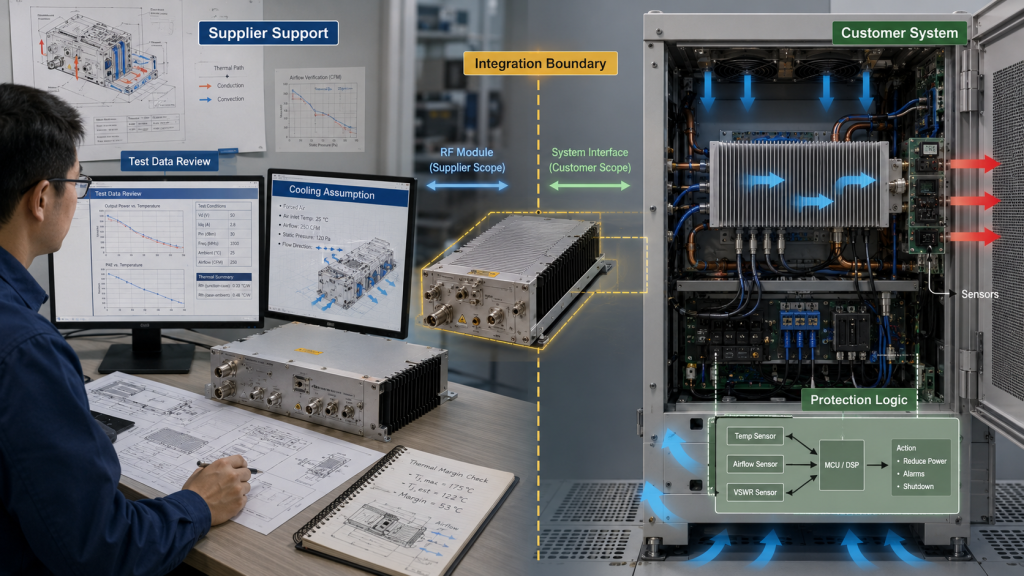
10.How Can Suppliers Help Avoid Airflow Misjudgment?
Suppliers can help avoid airflow misjudgment by defining module limits, external cooling assumptions, protection behavior, and test conditions clearly. RF Power Amplifier Cabinet Airflow should be discussed as part of the module integration boundary, especially for high-power C-UAS core components.
A mature supplier should not simply say that the module has a certain frequency, power level, and size. Here’s the practical risk: without cooling boundary information, a customer may treat a cabinet airflow problem as a module quality problem.
What should supplier support clarify?
Supplier support should clarify what the module can control internally and what the system integrator must provide externally. This prevents unrealistic expectations during cabinet design.
Useful clarification points include:
- External heatsink requirement
- Module base mounting condition
- Temperature detection behavior
- Thermal protection response
- Recommended test duration
- Load and airflow assumptions
- Data needed for troubleshooting
The practical risk is clear: if these boundaries are unclear, thermal discussions become guesswork after installation.
How does source-factory support reduce mistakes?
Source-factory support can connect amplifier design, mechanical mounting, heatsink assumptions, protection logic, and RF load testing into one discussion. That is different from treating cooling as a separate fan purchase.
Support can help customers review:
- Module thermal path
- Cabinet airflow layout
- External heatsink contact
- Long-duty RF test condition
- Protection alarm interpretation
- Batch consistency and test records
Key Takeaway: Good supplier support helps you separate module thermal performance from cabinet airflow problems. That saves time during integration, acceptance testing, and field troubleshooting.
| Supplier Input | Customer Benefit | Misjudgment Avoided |
|---|---|---|
| Cooling boundary | Knows external requirements | Blaming module for weak airflow |
| Protection logic | Understands alarm behavior | Treating protection as failure |
| Test condition | Runs realistic validation | Passing only open-bench tests |
| Mechanical review | Improves heatsink contact | Missing mounting problems |
| Data request | Speeds troubleshooting | Guessing from symptoms |
This table shows why RF module support should include system boundary discussion, not only a product specification sheet.
FAQ
Can I judge RF amplifier cooling by fan size alone?
No. Fan size does not prove usable airflow through the cabinet, heatsink, filter, and exhaust path. You need to check airflow direction, static pressure, heat recirculation, and closed-cabinet temperature behavior.
What’s the best way to test cabinet airflow?
The best way is to test under real RF load with the cabinet closed. Record inlet temperature, exhaust temperature, module shell temperature, output power, DC voltage, fan state, and run time.
How do I know if overheating is caused by airflow?
You know airflow is likely involved when open-bench testing passes but closed-cabinet testing shows rising temperature, output reduction, or temperature alarms. Compare door-open and door-closed results, then check inlet and exhaust temperatures.
Can a stronger heatsink solve poor cabinet airflow?
Not always. A stronger heatsink can spread heat better, but it still needs air to remove heat from the cabinet. If hot air is trapped or recirculated, the heatsink will still heat up over time.
What’s the best layout for multiple RF modules in one cabinet?
The best layout gives each module access to cool intake air and prevents one module’s exhaust from entering another module’s intake. Keep cable bundles out of the main airflow path and verify the final layout under simultaneous load.
Conclusion
Cabinet airflow explains why an RF Power Amplifier can behave differently on an open bench than inside a real cabinet. This article covered fan size limitations, heatsink airflow, static pressure, cabinet resistance, heat recirculation, long-duty output, airflow evaluation, test data, and supplier support. The core lesson is simple: cooling is not finished when heat reaches the heatsink; the cabinet must remove that heat from the system.
For C-UAS integrators, fixed-site security platforms, vehicle-mounted systems, and multi-channel RF cabinets, this is a practical engineering boundary. We can help you review RF module selection, external heatsink assumptions, cabinet airflow conditions, full-load test data, and protection behavior before field deployment. If you need factory-direct RF core component support for a real integration project, contact us today.
Stable RF output is built at the system boundary, where the amplifier, heatsink, airflow path, and validation method are engineered together.