


Grounding wires affect RF power amplifier system stability because they define the return path, reference point, shielding boundary, and noise behavior of the whole RF chain. In a C-UAS cabinet, vehicle-mounted jammer, airport perimeter system, or fixed-site RF platform, the amplifier module is not working alone. It shares power distribution, control signals, SDR sources, antennas, cable shields, test equipment, and metal structures with other devices.
This is why RF Power Amplifier Grounding should not be treated as a final wiring detail. A module may pass a bench test on a clean power supply and 50Ω dummy load, but behave differently after it is installed into a real cabinet with long harnesses, multiple modules, fans, controllers, and RF output cables. If the ground path is unclear, high-current return and noise can enter control and measurement paths. The result may look like module instability, false alarm, drifting feedback, communication errors, or unstable test data.
The practical solution is not simply “connect more ground wires.” The solution is to define which ground path carries current, which point acts as the signal reference, how the chassis is bonded, and how control signals remain protected from RF and power noise.
1.What Grounding Points Matter in RF Amplifier Systems
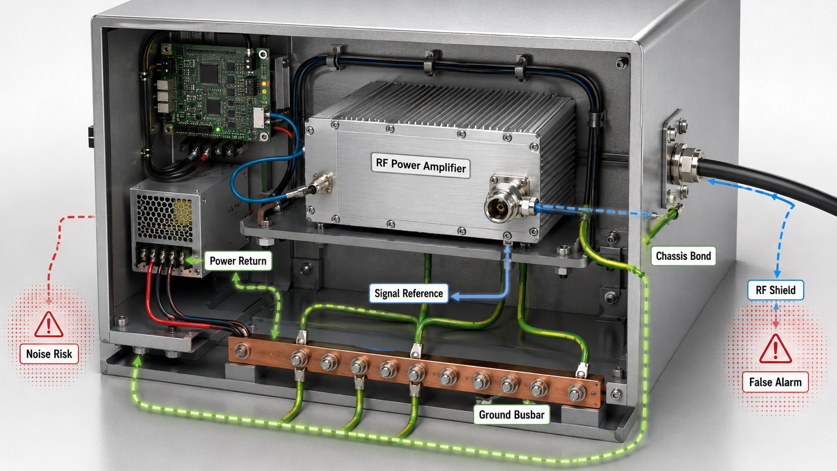
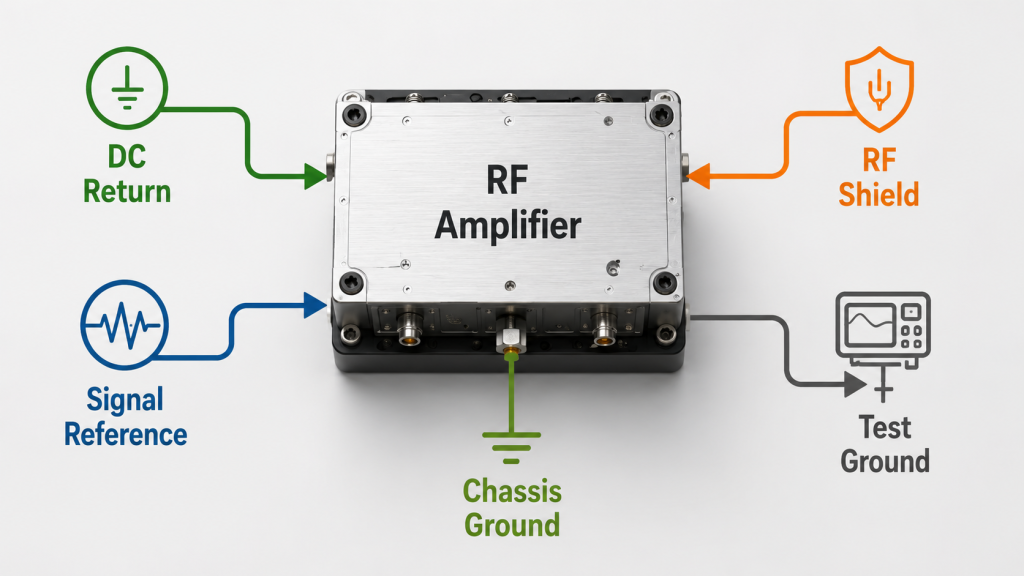
Grounding in an RF Power Amplifier Grounding discussion means return paths, reference points, shielding behavior, and safety bonding working together. It is not only one wire connected to a metal case. In a real RF system, “ground” may refer to the DC negative return, module GND, chassis ground, signal reference ground, RF connector shield, controller ground, test instrument ground, or protective earth.
Here’s the engineering point: these grounds may be connected, but they do not always carry the same current or noise. If you treat every ground as the same node without considering current direction, cable length, impedance, and shared return paths, the system may power on but still become unstable under RF load.
Why one ground name can hide several paths
Different ground functions exist because each one serves a different system purpose. A power return path must handle current, while a control reference must stay quiet enough for the controller to read status and alarm signals correctly.
- DC negative return carries operating current.
- Chassis ground supports shielding and mechanical bonding.
- Signal ground defines the control reference.
- RF shield ground affects coupling and EMI behavior.
- Test equipment ground can change the measurement reference.
Key Takeaway: Grounding should be defined by function, not only by connection point. When you separate power return, chassis bonding, signal reference, and RF shield behavior during planning, you reduce noise and troubleshooting confusion later.
| Ground Function | Main Role | Stability Risk if Unclear |
|---|---|---|
| DC return | Carries module current | Voltage shift and shared noise |
| Signal reference | Defines control logic levels | False alarm or status drift |
| Chassis ground | Provides bonding and shielding | EMI leakage or coupling |
| RF shield path | Controls RF boundary | RF noise entering harnesses |
| Instrument ground | Sets test reference | Measurement drift |
This table helps you avoid one common mistake: assuming that all ground labels mean the same thing in a high-power RF system.
2.How to Define Proper Grounding Paths in RF Amplifiers
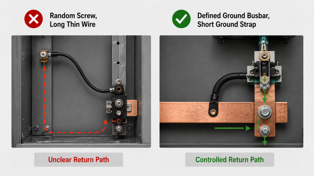
A ground path is different because RF Power Amplifier Grounding depends on where current returns, not only where a wire touches metal. A random screw on a cabinet may be mechanically convenient, but it may not provide the quiet, low-impedance, controlled path your amplifier and controller need. Two metal points can still have different potentials when high current, cable resistance, RF energy, or vibration enters the system.
The practical risk is clear: a ground connection is only useful when its return path is controlled. If the return path crosses sensitive control wiring, shares a thin harness with monitoring signals, or runs through a noisy chassis section, the amplifier may look unstable even when the RF output stage is healthy.
What makes a ground point trustworthy?
A trustworthy ground point is not only conductive. It must be suitable for the current, frequency behavior, mechanical reliability, and reference stability required by the system.
- It is close to the intended return point.
- It has low resistance and low practical impedance.
- It does not force high current through control wiring.
- It has clean metal-to-metal contact.
- It is repeatable across production units.
Key Takeaway: Connecting to metal is not the same as designing a ground path. For vehicle, cabinet, and fixed-site RF systems, the ground path should be planned together with power distribution, module placement, and control harness routing.
| Grounding Choice | Looks Acceptable? | Engineering Risk |
|---|---|---|
| Random cabinet screw | Yes | Uncontrolled return path |
| Long thin ground wire | Yes | Reference drift under load |
| Shared control/power ground | Sometimes | Noise enters signals |
| Short bonded ground strap | Yes | Lower path uncertainty |
| Defined ground busbar | Yes | Easier repeatability |
The best ground point is the one that makes current flow predictable, not the one that is easiest to reach.
3.How to Minimize Noise with Effective Grounding
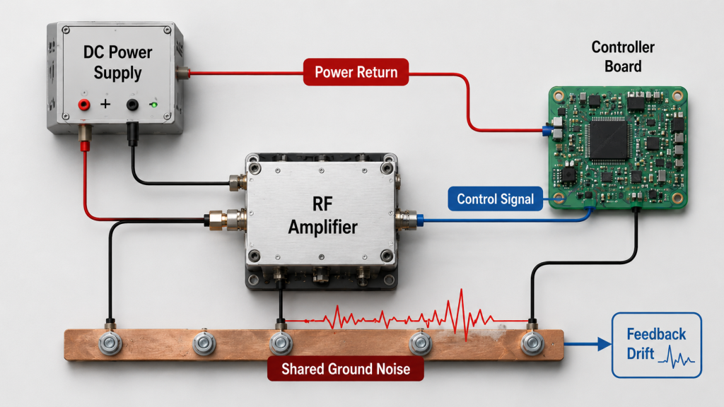
Poor grounding introduces noise because RF Power Amplifier Grounding controls how power noise, RF leakage, and switching currents return to the system reference. A high-power RF module can create large current changes, heat-related fan activity, monitoring feedback, and strong RF fields inside a compact cabinet. If those currents share ground impedance with control or measurement circuits, noise can appear where the controller expects a clean signal.
Here’s the field reality: the noise may not look like a dramatic failure. It may appear as small data jumps, unstable analog feedback, intermittent communication errors, or occasional alarm behavior that is hard to repeat.
Where does the noise enter?
Noise often enters through shared impedance and poor routing rather than through a single obvious broken wire. This is why grounding problems can be slow to diagnose.
- High-current return shares a path with control ground.
- RF cable shield current flows through the cabinet.
- Fan or relay noise couples into signal reference.
- Long ground wires pick up external interference.
- Test equipment creates another reference path.
Key Takeaway: Poor grounding lets power noise and RF energy enter measurement and control paths. When you see unstable readings, you should check whether the signal is truly wrong or whether the reference point is moving.
| Symptom | Possible Grounding Cause | What to Check |
|---|---|---|
| Analog feedback drift | Shared return impedance | Module GND to controller GND |
| Communication errors | Noisy reference | Cable routing and isolation |
| Raised noise floor | RF shield coupling | Connector and chassis bonding |
| Status flicker | Ground reference shift | Alarm/Status ground path |
| Test data jitter | Instrument ground loop | Bench grounding layout |
This is why a stable RF system is not judged only by amplifier output power; the reference paths must also stay quiet.
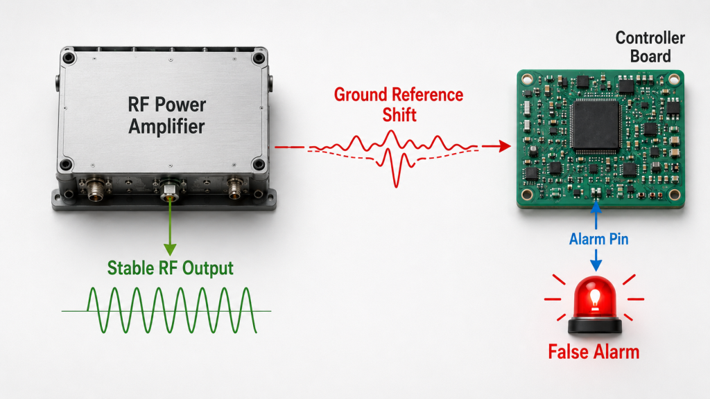
4.Why Can Grounding Problems Trigger False Alarms?
Grounding problems can trigger false alarms because RF Power Amplifier Grounding provides the reference that alarm, status, reset, current, voltage, and temperature feedback signals depend on. If that reference shifts or receives noise, the controller may see a false logic level or a distorted analog value. The amplifier may not be in real protection, but the system may report it as if it were.
This is where system integrators should pay attention: feedback signals are only as reliable as their reference path. When Alarm, Status, Reset, and reporting signals behave strangely, engineers should check the ground reference before assuming the control logic itself is wrong.
Why alarm pins are sensitive to ground noise
Alarm and status signals often appear simple, but they sit inside a noisy power system. A short pulse, floating reference, or poor common ground can confuse the controller.
- Alarm pin briefly changes state.
- Reset line receives a noise pulse.
- Enable logic becomes unstable.
- Temperature feedback appears higher than reality.
- Current or voltage reporting shifts under load.
Key Takeaway: False alarms often appear when the controller sees noise on a signal that should have a stable ground reference. Before replacing the amplifier module, verify whether the alarm condition remains when the ground reference is cleaned up.
| Feedback Signal | Normal Purpose | Grounding-Related Failure Mode |
|---|---|---|
| Alarm | Fault reporting | False trigger or flicker |
| Status | Operating state | Unstable state reading |
| Reset | Recovery control | Unwanted reset pulse |
| Current report | Load monitoring | Drifting analog value |
| Temperature report | Thermal monitoring | Incorrect protection judgment |
If the alarm disappears after grounding changes, the root cause was likely system wiring, not the amplifier protection circuit.
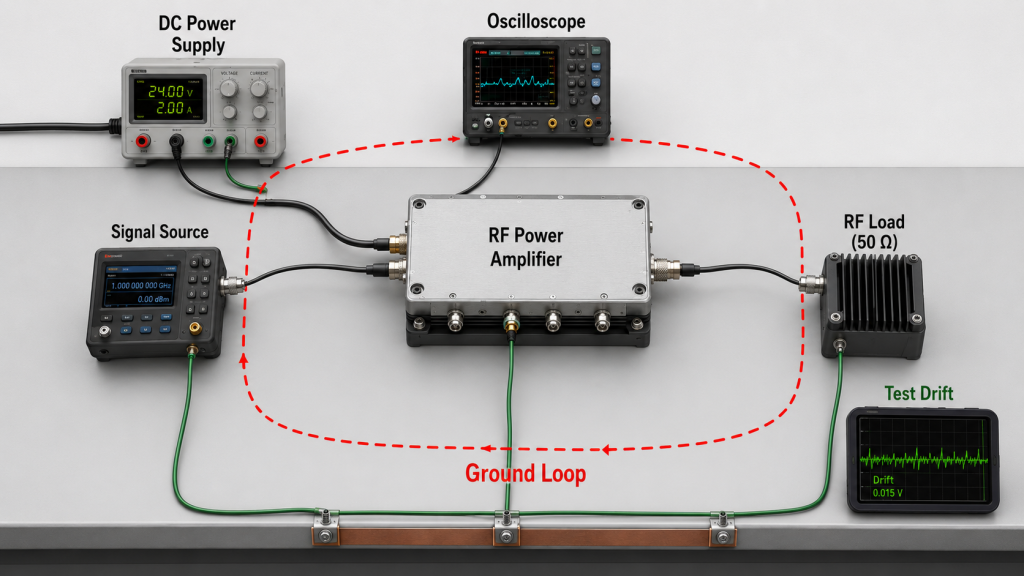
5.What Ground Loops Reveal About RF Amplifier Grounding
Ground loops create problems because RF Power Amplifier Grounding becomes unclear when several ground paths exist at the same time. A loop can form between the power supply, cabinet, oscilloscope, signal source, controller, RF cable shield, and protective earth. Once the loop exists, noise current can flow through measurement or control paths that were never meant to carry it.
Here’s the engineering point: a ground loop can make test data look unstable even when the amplifier output stage is not the real problem. This is especially common when a module passes single-unit testing but behaves differently during full cabinet integration.
How ground loops appear during testing
Ground loops often appear because bench instruments introduce their own ground references. The test setup becomes part of the circuit.
- Oscilloscope ground connects to protective earth.
- Signal generator shield connects to another ground point.
- Power meter and load add shield paths.
- Cabinet chassis is bonded at more than one location.
- Controller USB or Ethernet creates another reference.
Key Takeaway: Measurement instability may come from the test setup, not the RF module. When readings drift, compare single-module tests, cabinet tests, and instrument grounding before judging amplifier reliability.
| Loop Source | Typical Effect | Practical Check |
|---|---|---|
| Oscilloscope ground | Noise or shifted reference | Use safe differential methods |
| Signal source shield | Extra RF return path | Check shield continuity |
| Cabinet bonding | Multiple current paths | Map chassis connections |
| Controller interface | Reference conflict | Check isolated communication |
| RF cable shield | Coupled RF current | Verify connector bonding |
A clean test layout helps you avoid blaming the module for a problem created by the measurement system.
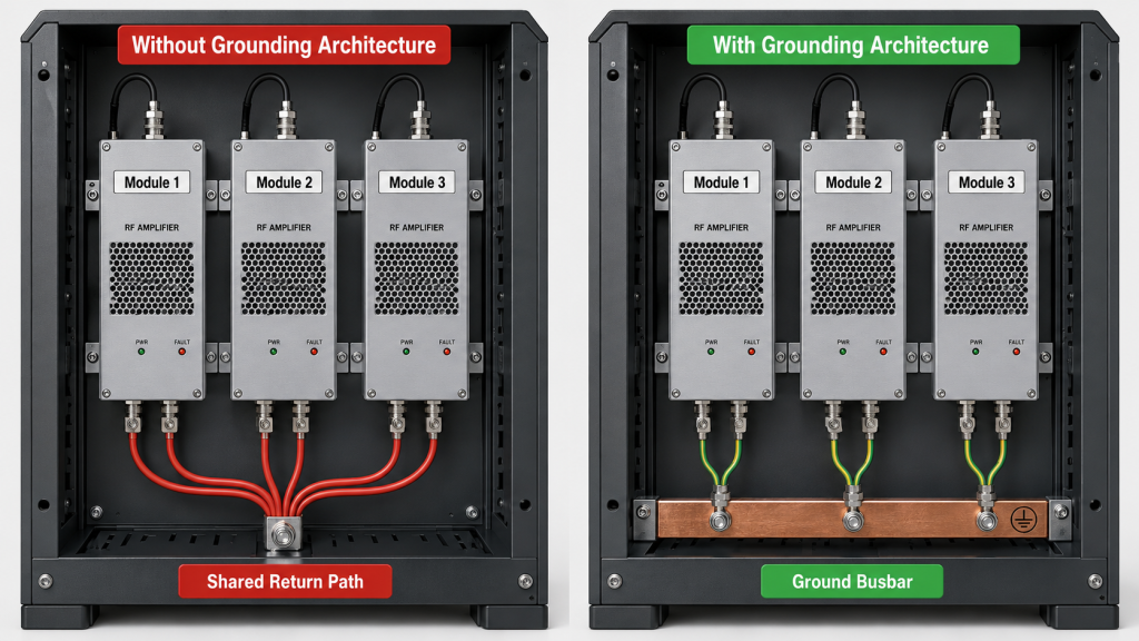
6.What Grounding Architecture Ensures Multi-Module Stability
Multi-module systems need grounding architecture because RF Power Amplifier Grounding becomes harder when several amplifiers, SDR sources, controllers, fans, antennas, and power paths share the same cabinet. One module may run cleanly by itself, but several modules operating together can create shared return currents and noise coupling. Without a clear grounding structure, one channel can affect another channel’s control or monitoring behavior.
The field reality is simple: multi-module RF systems need architecture, not random ground wires. In low-altitude security and C-UAS systems, multiple RF channels, SDR sources, antennas, and control boards must share a stable system environment rather than depend on improvised wiring.
What changes when several modules work together?
The return current grows, and the number of coupling paths increases. A grounding method that worked for one module may not be safe for a full RF assembly.
- Module returns may share one undersized path.
- Fan current may enter controller reference.
- RF cable shields may connect across several chassis points.
- Different modules may see different ground potentials.
- Alarm signals may become unstable only at full load.
Key Takeaway: Multi-module RF systems need a defined grounding structure before wiring begins. This reduces channel-to-channel interference, false alarms, and late-stage cabinet rework.
| Multi-Module Issue | Grounding Reason | Integration Impact |
|---|---|---|
| One module affects another | Shared return path | Hard-to-repeat faults |
| Alarm appears only at full load | Reference shift | False protection judgment |
| Controller readings differ by channel | Unequal ground paths | Calibration confusion |
| RF noise enters harness | Poor shield bonding | EMI symptoms |
| Cabinet rework required | No early ground plan | Delayed acceptance |
When more channels are added, grounding moves from a wiring detail to a system-level design decision.
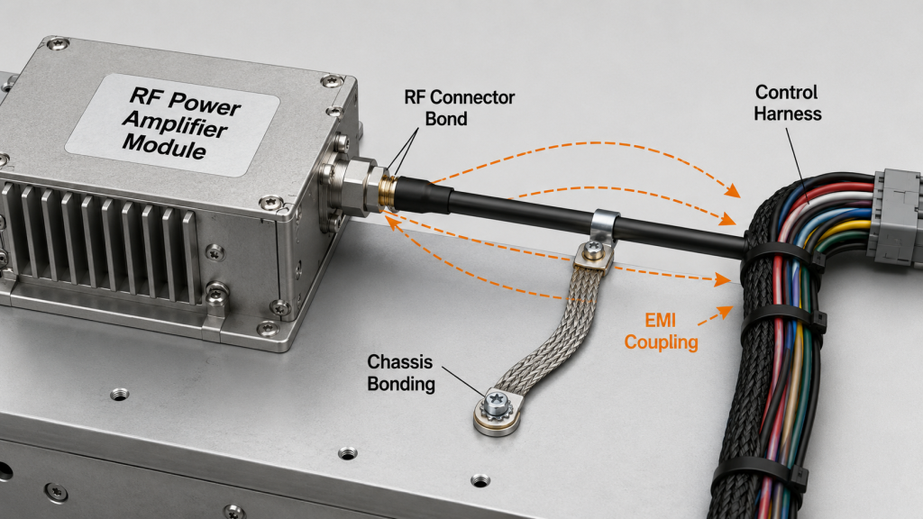
7.How Does Grounding Affect RF Shielding and EMI Behavior?
Grounding affects shielding because RF Power Amplifier Grounding decides whether shields, housings, connector bodies, and cabinet structures control RF energy or become unintended coupling paths. A shield without a clear ground path may not behave like a shield in a real system. It may carry unwanted current, radiate noise, or couple RF energy into nearby control wiring.
This is where the system context matters. In airport and perimeter systems, protected communications and adjacent sensitive RF channels make grounding, shielding, and cable routing part of the RF safety margin.
Why shields can become coupling paths
A shield must be connected in a way that supports its purpose. If the connection is long, loose, or forced through a noisy path, the shield can create new problems.
- RF connector outer conductor has poor chassis contact.
- Cable shield connects at unintended points.
- Long shield drain wire increases impedance.
- Control harness runs beside RF output cable.
- Cabinet panels lack reliable bonding.
Key Takeaway: Shielding works only when grounding supports it. A stable RF enclosure, connector bond, and cable routing plan can reduce EMI symptoms that might otherwise be mistaken for amplifier instability.
| Shielding Detail | Good Practice | Risk if Ignored |
|---|---|---|
| RF connector body | Firm bonded contact | Leakage or coupling |
| Cable shield | Controlled termination | Unwanted current path |
| Cabinet panels | Reliable bonding | EMI gaps |
| Control harness | Separated from RF output | Noise pickup |
| Ground strap | Short and wide | High RF impedance |
For RF systems, grounding and shielding are not separate topics; they are two parts of the same noise-control structure.
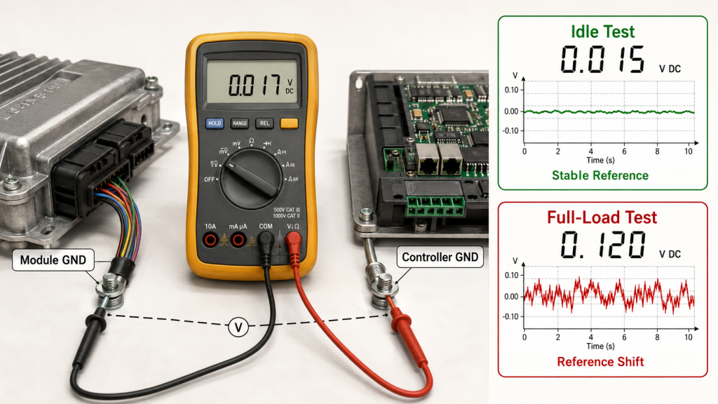
8.How to Test RF Amplifier Grounding for Stability
Engineers can check grounding by comparing RF Power Amplifier Grounding behavior under idle, full-load, single-module, and full-system conditions. A visual inspection is not enough. A ground wire may look connected, but the real question is whether the reference remains stable when current, RF output, fans, controllers, and instruments are active.
Here’s the practical test mindset: grounding should be checked under real operating load, not only during idle inspection. If an alarm, control error, or measurement drift appears only at high output power, the ground path must be tested under the same condition.
What should you test first?
Start with the paths that carry current and the points that define control reference. Then compare what changes between bench and system operation.
- Measure module GND to controller GND under load.
- Check whether high-current return shares control ground.
- Compare idle and full-power feedback readings.
- Move control harness away from RF and DC power paths.
- Test one module, then test all modules together.
- Check whether instrument grounds change the symptom.
Key Takeaway: Grounding faults often reveal themselves only when the system is operating like it will in the field. A full-load comparison can separate module failure from wiring, cabinet, or test setup problems.
| Check Item | Idle Test | Full-Load Test |
|---|---|---|
| Module GND to controller GND | May look normal | Shows reference shift |
| Alarm signal | Stable | May flicker |
| Analog feedback | Clean | May drift |
| Instrument reading | Repeatable | May become unstable |
| Multi-module operation | Not tested | Reveals shared path issues |
If the symptom changes when the grounding path changes, you have found a system-level clue.
9.What Grounding Details Should Be Confirmed Before Integration?
Grounding details should be confirmed before integration because RF Power Amplifier Grounding is much easier to control during layout than after the cabinet is wired. Late-stage ground fixes often add new paths, new loops, and new confusion. A ground wire added after a false alarm appears may hide the symptom while creating another return path somewhere else.
The practical risk is clear: grounding should be defined before wiring. If you wait until the system fails during final test, you may need to redesign harness routing, cabinet bonding, power distribution, and control reference at the same time.
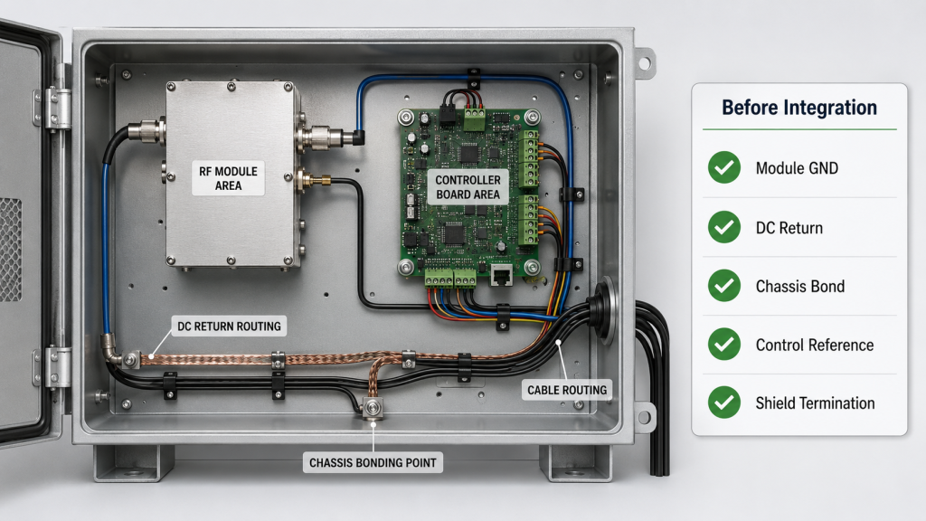
What should be reviewed before cabinet wiring?
The review should connect the module, power supply, controller, chassis, RF output path, and test setup. It should not be left to final assembly.
- Module GND definition.
- DC negative return route.
- Chassis bonding point.
- Controller reference ground.
- RF connector outer conductor path.
- Shield termination method.
- Power and ground wire gauge.
- Multi-module common point.
- Test equipment grounding plan.
- Alarm signal filtering or isolation need.
Key Takeaway: Grounding review before integration reduces false alarms, unstable feedback, and late wiring changes. It also helps purchasing and engineering teams judge whether a supplier understands system-level RF behavior.
| Detail to Confirm | Why It Matters | Best Time to Decide |
|---|---|---|
| Module GND | Defines return reference | Before harness design |
| Chassis bond | Supports shielding | Before cabinet assembly |
| Control reference | Stabilizes feedback | Before controller layout |
| Shield termination | Controls EMI path | Before cable routing |
| Multi-module ground point | Prevents shared noise | Before power distribution |
A clear grounding plan saves more time than a late-stage troubleshooting patch.
10.How Do Suppliers Help Reduce Grounding-Related Misjudgment?
Suppliers help reduce grounding-related misjudgment by treating RF Power Amplifier Grounding as part of system integration, not as a customer-side afterthought. A mature supplier should help you separate true module faults from cabinet wiring, shared return paths, noisy references, and ground-loop measurement errors. This prevents unnecessary returns, repeated tests, and delays during acceptance.
This is where source-factory RF core component support becomes useful. For tactical defense systems, reducing integration complexity requires compatible RF modules, SDR sources, antennas, control paths, and grounding strategy to be considered together.
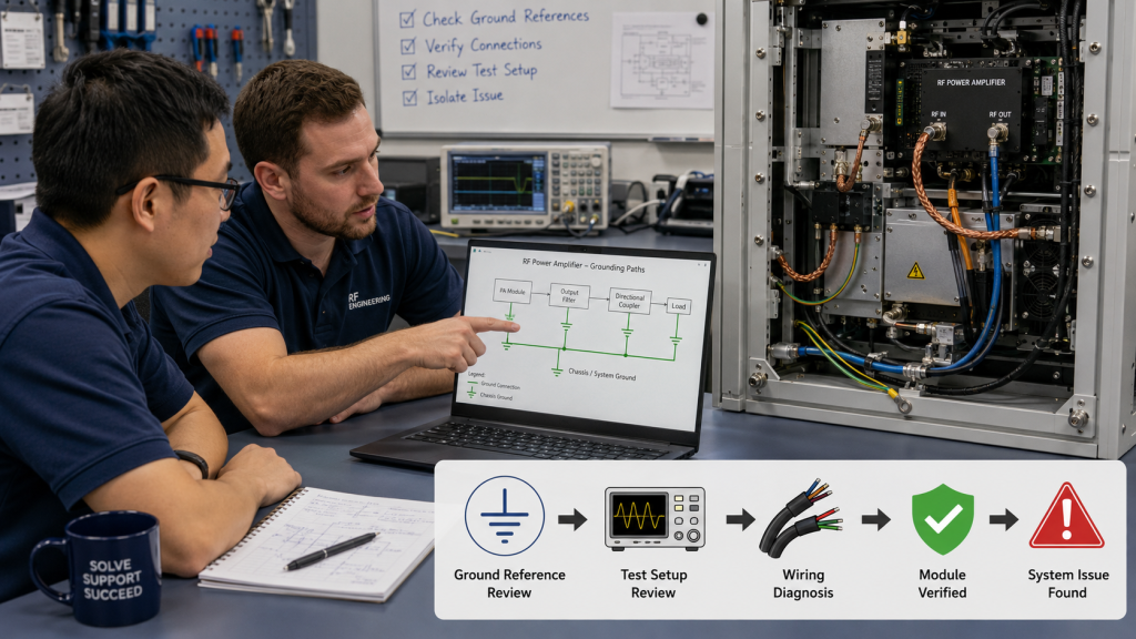
What support should you expect?
Good support is not limited to frequency and wattage selection. It should help you avoid misreading system wiring issues as amplifier quality problems.
- Clarify module GND and interface reference.
- Review alarm, reset, and reporting signal needs.
- Recommend separation of power return and control paths.
- Discuss shielding and chassis bonding.
- Support repeatable test setup planning.
- Help compare bench results and cabinet results.
Key Takeaway: A good RF power amplifier supplier helps customers separate real module faults from grounding and system-wiring problems. This is especially valuable in C-UAS systems where RF power, control logic, SDR sources, antennas, and cabinets must work together.
| Supplier Support Area | Customer Benefit | Misjudgment Reduced |
|---|---|---|
| Ground reference review | Stable control feedback | False alarm blame |
| Power return guidance | Lower shared noise | Voltage and noise confusion |
| Test setup advice | Repeatable data | Instrument-related drift |
| Shielding discussion | Lower EMI risk | RF coupling symptoms |
| Multi-module planning | Cleaner integration | Channel-to-channel interference |
The right supplier does not use grounding as an excuse; it helps you prove where the real problem is.
FAQ
Can I connect the ground wire to any metal part of the cabinet?
No, not if system stability matters. A random metal point may be conductive, but it may not provide a controlled return path or stable reference point for the RF amplifier, controller, and measurement system.
What’s the best grounding method for a multi-module RF system?
A defined grounding architecture is best. Many systems use a planned ground bus, short bonding paths, separated high-current returns, and controlled signal references, but the exact layout depends on cabinet structure, power level, module count, and control design.
How do I know if grounding is causing false alarms?
Check whether the alarm changes with load, cable routing, instrument connection, or ground point changes. If the module works in single-unit testing but alarms inside the full cabinet, the ground reference and shared return paths should be reviewed.
Can poor grounding damage an RF power amplifier?
Yes, in some cases it can contribute to unsafe system behavior. Poor grounding may not directly damage the RF stage by itself, but it can cause unstable control, wrong protection judgment, EMI coupling, or incorrect test decisions that increase system risk.
What’s the best way to test RF amplifier grounding?
Test it under real operating load. Compare idle and full-power conditions, measure ground potential differences, check feedback stability, and repeat tests with single-module and full-system configurations.
Conclusion
Grounding wires affect RF power amplifier system stability because they shape the return path, reference point, shielding boundary, and measurement behavior of the whole RF system. This article showed why grounding is not just a safety wire, why metal contact is not the same as a controlled ground path, how poor grounding creates noise, why false alarms may appear, how ground loops distort test results, and why multi-module C-UAS systems need grounding architecture from the start.
For system integrators, the practical lesson is direct: do not judge amplifier reliability only from the module label, output power, or bench result. Review the module GND, power return, chassis bond, control reference, RF shield, instrument ground, and cabinet layout together. RF SKYPOWER can support RF module selection, interface review, grounding discussion, and source-factory integration planning for C-UAS, airport, perimeter, tactical defense, and fixed-site RF systems. If you need help reviewing the RF amplifier, power path, control reference, and grounding structure together, contact us today.
Stable RF defense is not built by adding more wires after failure; it is built by controlling every path that power, noise, signal, and RF energy can follow.