


RF power loss caused by DC cable size can be avoided by measuring the amplifier input voltage under load, selecting cable gauge based on real current demand, and checking the complete DC supply path before full-power operation. In a fixed-site C-UAS cabinet, vehicle-mounted RF system, or multi-channel perimeter defense installation, the DC supply cable is not just a wiring accessory. It is part of the operating condition that allows the amplifier to reach rated output.
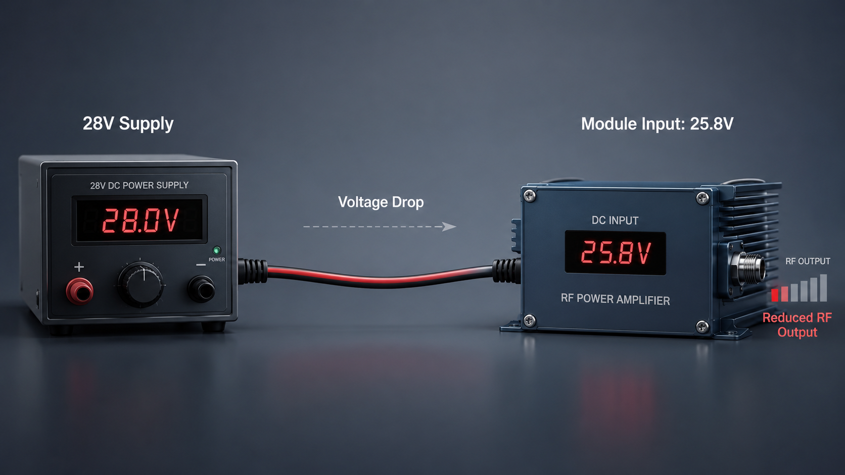
A common field situation looks simple at first: the power supply display shows 28V, the RF path appears connected, and the amplifier still fails to reach expected power. This is where RF Power Amplifier Voltage Drop becomes a practical integration problem. If the DC cable is too thin, too long, or connected through weak terminals, the voltage measured at the amplifier input can be lower than the voltage shown at the supply.
The solution is not to assume that a thicker cable automatically solves every issue. Engineers should verify module-terminal voltage under real load, review cable size against current demand, and treat the DC input path as part of RF system performance.
1.What Does Cable Size Mean in RF Amplifier Systems?
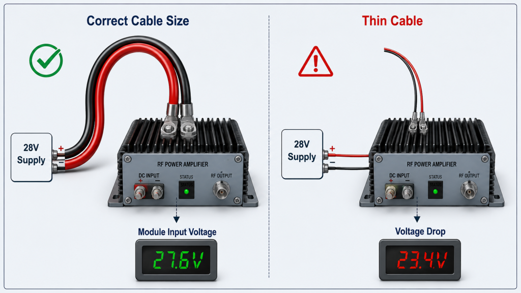
DC cable size means the conductor capacity that determines whether a RF Power Amplifier Voltage Drop appears when the amplifier draws high current. In RF systems, the cable between the power supply and the module has resistance, even when it looks short and clean. Under low current, that resistance may not matter much. Under full RF output, the same resistance can become visible as voltage loss.
Here’s the engineering point: cable size is not only about whether the wire can physically connect the module. It affects how much voltage reaches the amplifier input when the module is operating at rated power. For high-power RF modules, a cable that looks acceptable during idle testing may become a weak link during full-load operation.
Why Is Wire Gauge More Than a Wiring Detail?
Wire gauge affects resistance, current handling, voltage drop, and heat rise. A thinner conductor has higher resistance, so the same current creates more voltage loss across the cable.
You should evaluate wire gauge together with:
- Maximum amplifier current
- Cable length from supply to module
- Continuous duty cycle
- Cabinet or vehicle temperature
- Connector and terminal ratings
For RF system integrators, this is why cable size should be reviewed before full-load testing, not after output power looks low.
Why Does Cable Length Change the Result?
Cable length increases total resistance, so even a reasonable wire gauge can create voltage drop if the run is long. The return path also matters, because current must travel through both positive and negative conductors.
A practical review should include:
- One-way cable distance
- Total loop length
- Routing through cabinets or vehicle frames
- Voltage measured at the module input
- Heat around the cable and terminals
Longer routing may be unavoidable, but it should be part of the power calculation.
What Is the Key Integration Risk?
The main risk is assuming that a cable is acceptable because the amplifier powers on. Power-on behavior does not prove that the cable can support full current under RF load.
Key Takeaway: DC cable size affects whether the amplifier receives enough voltage during real operation. If you only check whether the module turns on, you may miss the voltage drop that appears during full output.
| Cable Detail | Why It Matters | Field Risk |
|---|---|---|
| Wire gauge | Controls conductor resistance | Thin cable causes voltage drop |
| Cable length | Adds total resistance | Long runs lower module voltage |
| Current load | Increases voltage loss | Full power exposes weak wiring |
| Duty cycle | Sustains heating | Cable and terminals run hot |
| Routing path | Adds hidden losses | Cabinet layout affects voltage |
This table shows why cable selection should be treated as part of RF performance planning, not only electrical installation.
2.What Causes Cable Voltage Drop at Module Input?
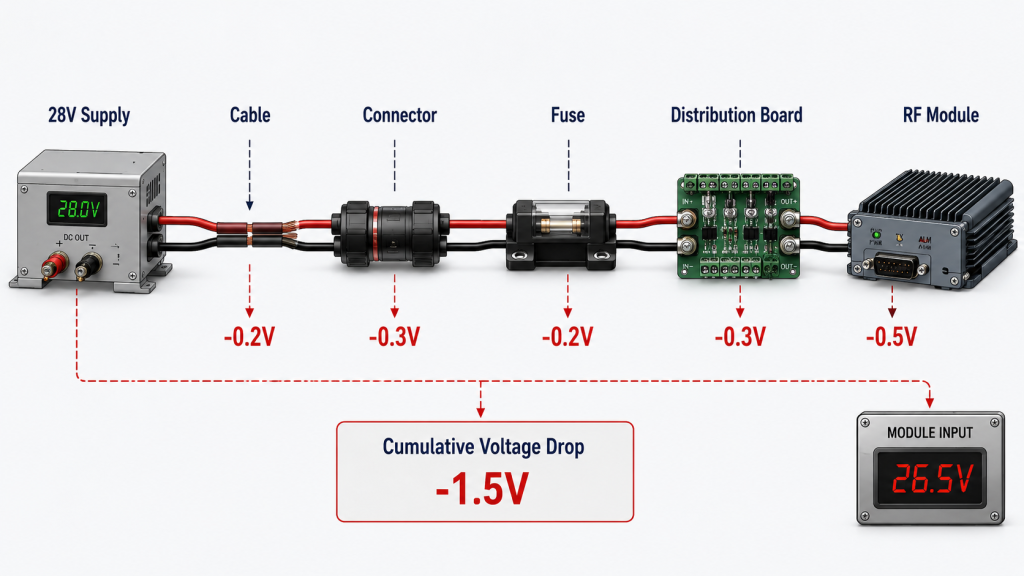
Power supply voltage and module voltage are different because RF Power Amplifier Voltage Drop occurs across cables, connectors, terminals, switches, fuses, and distribution boards. The voltage displayed on the power supply is measured at the supply output, not necessarily at the amplifier input. Once current rises, every small resistance in the supply path can reduce the voltage that reaches the module.
This is where system integrators should pay attention: the amplifier should be evaluated by the voltage at its DC input terminal during operation. For 28V high-power RF power amplifier modules, the voltage that matters during full-load testing is not only the power supply display, but the voltage actually received by the module.
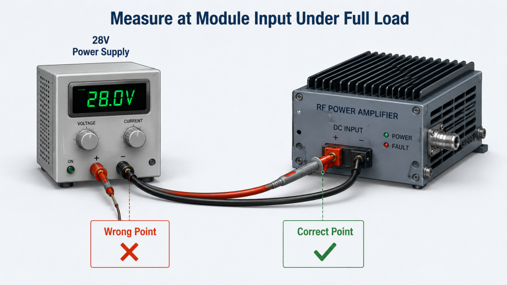
Where Should Voltage Be Measured?
Voltage should be measured as close as possible to the amplifier DC input terminal. Measuring only at the power supply can hide the drop across the cable path.
Useful measurement points include:
- Power supply output terminal
- DC distribution board output
- Connector input and output
- Amplifier DC input terminal
- Module input during full RF output
The most valuable reading is usually the module-terminal voltage under load.
Why Does Idle Testing Hide the Problem?
Idle testing draws much less current than full-power RF operation. Because voltage drop depends on current, a weak cable may look normal when the amplifier is not transmitting at full output.
You may see this pattern:
- Idle voltage looks normal
- Low-power test looks acceptable
- Full-power output drops
- Cable or terminal temperature rises
- Protection logic may trigger
That sequence often points back to the DC supply path.
What Should Engineers Record During Testing?
Engineers should record both supply-side and module-side voltage during the same operating condition. This helps separate real module issues from supply-path issues.
Key Takeaway: The voltage displayed on the power supply is not enough. Module-terminal voltage under load gives the real operating condition of the amplifier.
| Test Condition | Supply Display | Module Input | Engineering Meaning |
|---|---|---|---|
| Idle | 28V | 27.9V | Cable drop is not visible |
| Low output | 28V | 27.2V | Small drop appears |
| Full output | 28V | 25.8V | Cable path is limiting output |
| Multi-module load | 28V | 25V or lower | Distribution path may be undersized |
This comparison helps engineers avoid blaming the amplifier before checking the actual DC input condition.
3.How to Identify Cable Voltage Drop Under High Current?
Thin DC cables create RF Power Amplifier Voltage Drop because higher cable resistance turns part of the input energy into heat instead of delivering it to the module. The basic relationship is simple: voltage drop increases as current and resistance increase. A cable that works for low-current electronics may be unsuitable for a high-power RF amplifier.
Here’s the field reality: voltage drop often appears only when the amplifier current rises. That means a system can pass a simple power-on check but fail during real RF output. This is why full-load testing should include module-terminal voltage measurement, not only RF output power measurement.
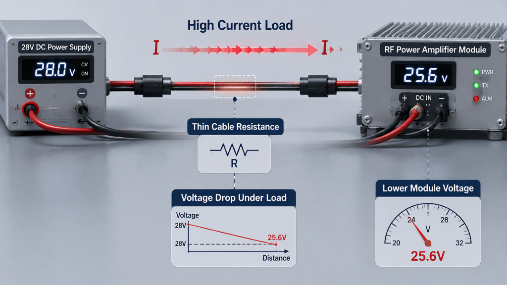
Why Does Current Make the Problem Worse?
Current is the factor that exposes cable resistance. As RF output increases, the amplifier draws more current, and the voltage loss across the cable becomes more obvious.
Watch for these signs:
- Voltage drops during RF power ramp-up
- Output power stops rising as expected
- Cable or connector becomes warm
- Module alarms appear near full load
- Multiple modules behave differently
These symptoms can point to a supply-path limitation.
Why Is Cable Resistance Not Always Obvious?
Cable resistance is small in absolute value, so it may be ignored during visual inspection. But in high-current systems, even small resistance can create meaningful voltage loss and heat.
Common hidden contributors include:
- Long cable runs
- Thin conductors
- Poor crimping
- Loose terminals
- Aging connectors
- Undersized distribution traces
The cable may look normal while still causing measurable voltage drop.
What Is the Practical Rule?
The practical rule is to size the cable for the highest expected current under real operating conditions, not for idle or short bench tests.
Key Takeaway: Thin DC cables do not always fail visibly. They reduce module voltage under load, which can reduce output power before any obvious wiring damage appears.
| Cause | Electrical Effect | RF System Result |
|---|---|---|
| Thin conductor | Higher resistance | Lower module voltage |
| Long cable | More total resistance | Larger voltage drop |
| High current | Higher I × R loss | Output power decreases |
| Poor terminal | Contact resistance | Heat and unstable voltage |
| Multi-module load | Shared current demand | Uneven module performance |
This table shows why cable size must be checked under the same load condition that the RF amplifier will face in deployment.
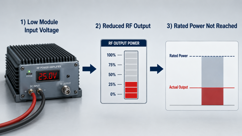
4.Why Does Output Power Drop When Module Voltage Falls?
Output power drops when module voltage falls because a RF Power Amplifier Voltage Drop reduces the DC supply margin available to the amplifier’s power stage. A high-power RF amplifier needs stable voltage and current to maintain rated output. If the module input voltage falls below the required operating condition, the amplifier may no longer produce the expected RF power.
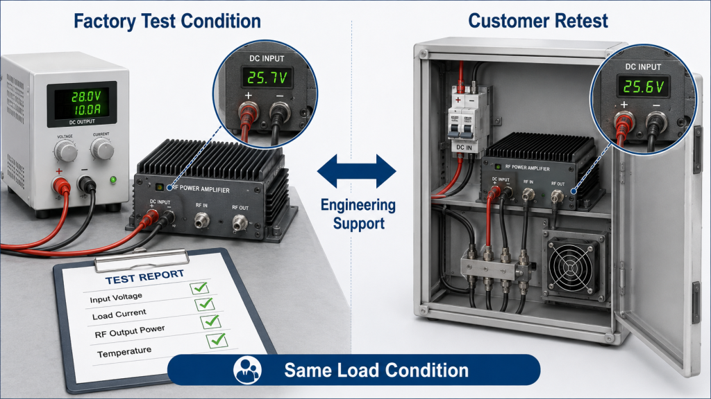
The practical risk is clear: customers may think the module is underperforming, overrated, or unstable. In reality, the amplifier may be healthy, but the DC input condition at the module is not the same as the condition used during factory testing.
How Does Lower Voltage Affect RF Output?
Lower voltage can limit the amplifier’s ability to maintain target output power. It may also change current draw, efficiency, and operating temperature.
Possible effects include:
- Lower RF output power
- Reduced headroom at high power
- Increased current stress
- Efficiency shift
- Earlier protection response
- Inconsistent output across channels
These effects can appear before a complete system shutdown.
Why Can Protection Logic Be Triggered?
Protection logic may respond when the amplifier operates outside its expected electrical condition. If voltage drops during high current, the module may enter a state that looks like a fault or instability.
Possible protection-related symptoms include:
- Alarm during power ramp-up
- Output reduction
- Intermittent operation
- Recovery after load decreases
- Repeated fault under multi-module operation
The root cause may still be the DC path, not the RF path.
What Should Be Checked Before Blaming the Module?
Before concluding that the amplifier has weak output, check whether its input voltage matches the required test condition.
Key Takeaway: A good RF amplifier cannot maintain rated output if the DC voltage at its input terminal is too low during full-load operation.
| Module Input Condition | Likely RF Behavior | Recommended Check |
|---|---|---|
| Stable rated voltage | Normal output | Continue RF path testing |
| Slight voltage drop | Minor output reduction | Check cable length and gauge |
| Large voltage drop | Clear output loss | Rework DC cable path |
| Drop during multi-module load | Channel inconsistency | Review power distribution |
| Drop before alarm | Protection risk | Measure voltage at alarm moment |
This table helps separate amplifier performance issues from DC supply-path problems.
5.What Cable Path Issues Add DC Voltage Loss?
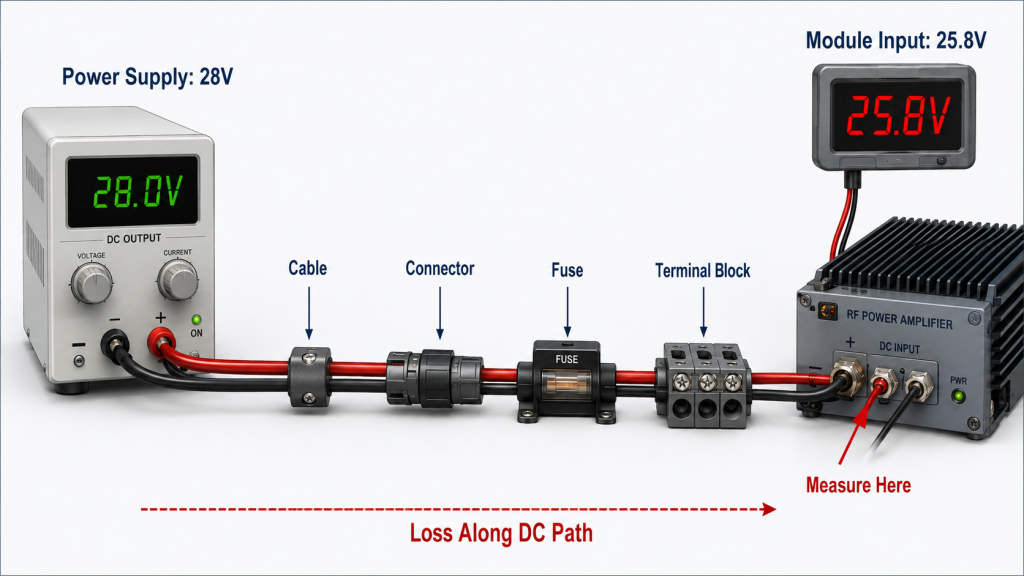
Cable length, connectors, and boards add loss because RF Power Amplifier Voltage Drop is created by the complete DC supply path, not only by the cable itself. A system may use a reasonable cable gauge but still lose voltage through long routing, contact resistance, fuse holders, switches, or distribution boards. Each small loss becomes more important as current increases.
Here’s the engineering point: the DC path includes every component between the power supply and amplifier input. If you only review the cable and ignore terminals, connectors, and boards, you may miss the actual source of the voltage drop.
Which DC Path Parts Should Be Reviewed?
The full DC path should be reviewed as one current-carrying chain. A weak point anywhere in the chain can lower module voltage.
Common items include:
- DC power cable
- Plug-in connector
- Terminal block
- Crimped lug
- Fuse or breaker
- Power switch
- Distribution board
- PCB copper path
- Ground return path
Each item should be rated for the current it will actually carry.
Why Do Connectors Become a Problem?
Connectors can add contact resistance if they are undersized, poorly crimped, loose, oxidized, or exposed to vibration. This resistance may create local heating and unstable voltage.
Connector-related warning signs include:
- Heat at the connector body
- Voltage difference across connector
- Darkened terminal surface
- Intermittent module behavior
- Output drop during vibration
- Repeated alarm under high load
In vehicle systems, vibration makes connector quality even more important.
How Should Distribution Boards Be Evaluated?
Distribution boards should be evaluated by current path capacity, not just physical layout.
Key Takeaway: Voltage drop is cumulative. A thin cable is one cause, but connectors, terminals, switches, and distribution boards can add enough loss to affect RF output.
| DC Path Element | Common Risk | What to Verify |
|---|---|---|
| Cable | Undersized conductor | Current rating and length |
| Connector | Contact resistance | Temperature and voltage drop |
| Terminal | Loose connection | Torque and crimp quality |
| Fuse or switch | Internal resistance | Rated current under load |
| Distribution board | Narrow copper path | Total current capacity |
| Return path | Shared resistance | Ground layout and loop length |
This table shows why the complete DC supply path should be reviewed before judging amplifier output.
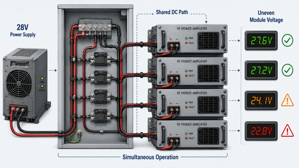
6.Why Do Multi-Module C-UAS Systems Need Better Cable Sizing?
Multi-module C-UAS systems need better cable sizing because RF Power Amplifier Voltage Drop increases when several RF channels draw current at the same time. A single module may perform normally, but a full system with multiple bands activated can place much higher demand on the DC supply path. Cable sizing should be based on total current demand, not only one amplifier.
This is where system integrators should pay attention: in vehicle-mounted and fixed-site C-UAS systems, RF modules are usually not isolated components. They operate as part of a multi-channel RF chain, so DC cable size, power distribution, connector rating, and module layout should be reviewed together.
Why Is Single-Module Testing Not Enough?
Single-module testing may hide system-level voltage drop. The supply path that looks acceptable for one amplifier may become insufficient when several channels operate together.
Multi-module risks include:
- Shared cable overload
- Uneven voltage between channels
- Output difference between bands
- Heat at distribution points
- System alarm during simultaneous operation
- Controller misreading module status
This is why full-system load testing matters.
How Does Power Distribution Affect Channel Consistency?
Power distribution affects whether each RF module receives similar voltage under load. Unequal cable lengths, connector types, or board paths can make one channel weaker than another.
You should compare:
- Voltage at each module input
- Cable length to each module
- Connector temperature per channel
- Output power per RF band
- Behavior during simultaneous activation
- Alarm timing across modules
A consistent supply path supports consistent RF output.
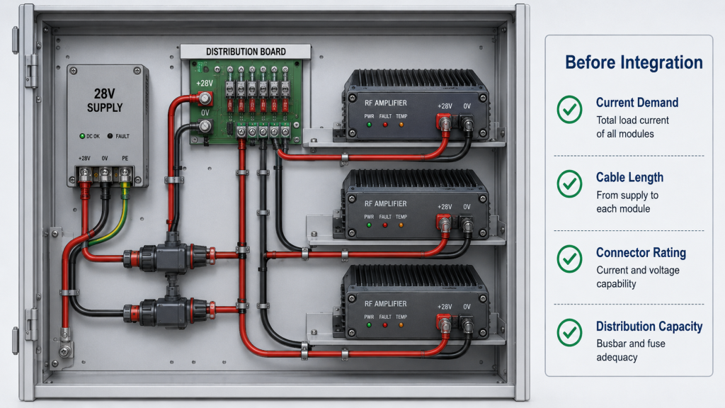
What Should Be Planned Before Cabinet Build?
The DC architecture should be planned before mechanical layout is finalized.
Key Takeaway: In multi-module C-UAS systems, DC cable sizing is a system-level design decision. The total current path must support simultaneous operation, not only one amplifier on the bench.
| Integration Factor | Why It Matters | Failure Pattern |
|---|---|---|
| Total current demand | Defines cable and bus size | Voltage sag under full load |
| Module count | Increases supply stress | Some channels output lower |
| Cable symmetry | Affects channel consistency | Uneven RF performance |
| Distribution board rating | Carries shared current | Heating and voltage drop |
| Cabinet routing | Changes cable length | Unexpected module undervoltage |
This table explains why C-UAS power design should be reviewed before the system reaches field deployment.
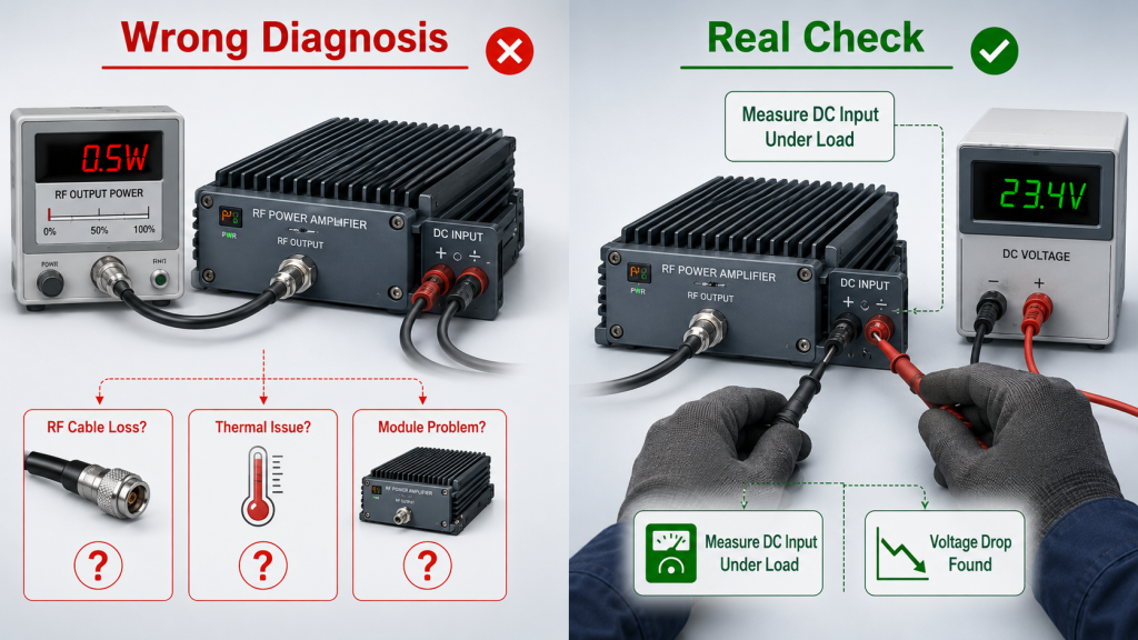
7.How Can Voltage Drop Be Mistaken for RF or Thermal Problems?
Voltage drop can be mistaken for RF or thermal problems because RF Power Amplifier Voltage Drop can make a healthy amplifier look weak, unstable, or heat-limited. If output power falls during full-load testing, engineers may first suspect feeder loss, antenna mismatch, thermal throttling, gain flatness, or module quality. Those issues are possible, but DC input voltage should be checked before the diagnosis goes too far.
Here’s the field reality: a power problem can imitate several different RF symptoms. If the module-terminal voltage drops when RF output rises, the root cause may be in the DC supply path even when the RF chain appears to be the problem.
Why Can It Look Like RF Cable Loss?
It can look like RF cable loss because the final measured RF output is lower than expected. However, RF cable loss happens after the amplifier output, while DC voltage drop happens before or during amplification.
Check these clues:
- Module output is low at the test port
- Module input voltage drops under load
- RF cable remains unchanged
- Output recovers with shorter DC cable
- Power supply display stays normal
- Cable terminals become warm
If the module output itself drops, the DC path deserves attention.
Why Can It Look Like Thermal Throttling?
It can look like thermal throttling because output may reduce during long-duty operation. But the first cause may be undervoltage, not heat transfer.
Compare these items:
- Module case temperature
- DC input voltage over time
- Output power over time
- Cable and terminal temperature
- Alarm log sequence
- Cooling fan or heatsink condition
If voltage falls before output reduction, the supply path may be the starting point.
How Should Engineers Avoid Misdiagnosis?
Engineers should check DC input voltage, RF output, thermal status, and alarm timing together.
Key Takeaway: DC voltage drop can imitate RF loss, thermal limits, or unstable module behavior. Measuring module input voltage under load prevents unnecessary troubleshooting in the wrong direction.
| Symptom | Common Assumption | DC Path Check |
|---|---|---|
| Low RF output | Module is weak | Measure module input voltage |
| Output drops over time | Thermal issue | Compare voltage and temperature |
| Alarm at high power | Load mismatch | Check voltage at alarm moment |
| Uneven bands | Gain flatness issue | Compare each channel voltage |
| Customer retest is low | Factory data mismatch | Match DC test conditions |
This table helps engineers avoid replacing or blaming the wrong part of the system.
8.How to Measure Cable Voltage Drop at Module Input?
Engineers should measure RF Power Amplifier Voltage Drop at the amplifier input while the module is operating under real load. A voltage measurement taken only at idle or only at the power supply is not enough. The test should reproduce the current demand that exists during real RF output.
The practical risk is clear: if you measure at the wrong point, you may record a normal 28V supply while the amplifier input is already much lower. That mistake can lead to incorrect conclusions about output power, module quality, or system stability.
What Measurement Sequence Works Best?
A useful measurement sequence compares voltage at multiple load levels. This shows when the voltage drop begins and how severe it becomes.
A practical sequence includes:
- Power supply output at idle
- Module input voltage at idle
- Module input at low RF output
- Module input at full RF output
- Module input during multi-module activation
- Voltage at the moment of alarm or output drop
This makes the voltage drop visible instead of assumed.
Where Should Probes Be Placed?
The voltage probe should be placed close to the amplifier input terminal. If you measure too far upstream, you may miss losses across connectors or terminal blocks.
Recommended probe points include:
- Directly at module input terminals
- Before and after connectors
- Distribution board input and output
- Across fuse or switch terminals
- At the end of long cable runs
- At each module in a multi-channel cabinet
The goal is to identify exactly where voltage is being lost.
What Other Signs Should Be Checked?
Voltage measurement should be paired with physical inspection and temperature checks.
Key Takeaway: Voltage drop should be measured at the amplifier input under load. Correct measurement location is often the difference between accurate diagnosis and wasted troubleshooting.
| Check Item | Correct Method | Why It Matters |
|---|---|---|
| Supply voltage | Measure at supply output | Confirms source condition |
| Module voltage | Measure at module input | Confirms real amplifier condition |
| Connector loss | Measure across connector | Finds contact resistance |
| Full-load voltage | Measure during RF output | Reveals current-related drop |
| Multi-module voltage | Measure each channel | Shows distribution imbalance |
| Cable temperature | Check after load period | Finds hidden resistance |
This table gives engineers a simple way to confirm whether the DC path can support real RF operation.
9.How to Check Cable Details Before RF Integration?
DC cable details should be confirmed before integration because RF Power Amplifier Voltage Drop is easier to prevent during design than to correct after the system is installed. Once a cabinet is built, cables are routed, and connectors are fixed, changing the DC path may require mechanical rework. Early confirmation reduces field risk.
This is where procurement and engineering should work together. Cable selection is not only a purchasing item. It affects RF output, thermal behavior, protection response, maintenance access, and customer acceptance testing.
Which Electrical Details Should Be Confirmed?
Electrical details should be based on maximum real operating demand, not only nominal current.
Confirm these items:
- Maximum module current
- Continuous operating current
- Startup or transient current
- Required input voltage range
- Allowed voltage drop
- Total current in shared paths
- Connector current rating
- Fuse and switch rating
The cable should support the worst expected operating case.
Which Mechanical Details Matter?
Mechanical details affect how the cable performs over time. A wire that is electrically acceptable on paper may fail in a cramped, hot, vibrating, or hard-to-service environment.
Review these items:
- Cable bend radius
- Cabinet routing distance
- Strain relief
- Connector locking method
- Vibration exposure
- Service access
- Heat near power components
- Outdoor or vehicle environment
Mechanical stress can turn a good design into a field problem.
How Should This Apply to Deployment Scenarios?
Deployment scenarios should guide the DC path design. In airport counter-UAS deployments, cabinet routing, remote equipment positions, and maintenance workflow can affect whether each RF module receives stable DC input during long-duty operation.
Key Takeaway: DC cable selection should be based on current, length, voltage drop, duty cycle, and installation environment. “It can connect” is not the same as “it can support rated RF output.”
| Detail to Confirm | Why It Matters | Best Timing |
|---|---|---|
| Maximum current | Defines cable size | Before cabinet design |
| Cable length | Defines voltage drop | Before routing plan |
| Connector rating | Prevents heating | Before procurement |
| Distribution capacity | Supports all modules | Before system layout |
| Duty cycle | Affects heat rise | Before full-load test |
| Maintenance access | Reduces field rework | Before installation |
This table shows why DC cable details should be treated as part of system integration, not a final wiring step.
10.How Do Experienced Suppliers Reduce Power-Drop Misjudgment?
Experienced suppliers reduce power-drop misjudgment by helping customers separate real module limitations from RF Power Amplifier Voltage Drop in the DC supply path. A supplier should not only state rated RF output. It should help define the operating conditions under which that output is measured and repeated.
Here’s the engineering point: factory data, customer retesting, and field deployment must use comparable conditions. If the factory tests the module at proper input voltage but the customer tests it through undersized wiring, the same module may appear to perform differently.
What Should Supplier Support Include?
Supplier support should include practical guidance on voltage, current, wiring, protection behavior, and test conditions. This reduces unnecessary blame on the module when the real issue is the supply path.
Useful support includes:
- Recommended input voltage condition
- Full-load current reference
- Cable and connector review
- Module-terminal voltage guidance
- Alarm behavior explanation
- Retest procedure alignment
- Multi-module power planning
This helps customers reproduce rated output more accurately.
Why Does Source-Factory Support Matter?
Source-factory support matters because the same team that understands the module design can also explain how external conditions affect performance. For critical infrastructure deployments, a small voltage drop in the DC path can become a system-level reliability issue when several RF channels need stable long-duty output.
A source-factory discussion can cover:
- Module electrical requirements
- DC cable path risks
- Connector and terminal quality
- Cooling structure relationship
- Protection logic response
- Test method consistency
That is more useful than only shipping a module and leaving integration questions unanswered.
What Is the Correct Supplier Mindset?
The correct supplier mindset is not to blame the customer’s wiring whenever output drops. The better approach is to help identify whether the issue comes from the module, RF path, DC path, thermal path, or test setup.
Key Takeaway: A good RF amplifier supplier helps customers verify the whole operating condition. Rated output is meaningful only when the module receives the voltage and current required to produce it.
| Supplier Role | Practical Value | Customer Benefit |
|---|---|---|
| Define test conditions | Matches factory and field testing | Reduces retest disputes |
| Review DC path | Finds voltage drop risk | Prevents output misjudgment |
| Explain alarms | Separates protection from failure | Speeds troubleshooting |
| Support multi-module layout | Improves system consistency | Reduces channel imbalance |
| Provide engineering guidance | Connects module and system behavior | Improves deployment reliability |
This table explains how supplier support can reduce confusion between true module limits and external supply-path problems.
FAQ
Can I use thinner DC cables if the amplifier powers on normally?
No. Power-on behavior does not prove the cable can support full-load current. A thin cable may show normal voltage at idle but create serious voltage drop when the RF amplifier reaches high output.
What’s the best way to check if cable size is causing output drop?
Measure voltage directly at the amplifier input during full-load RF operation. If the power supply shows normal voltage but the module input is lower, the DC path should be reviewed.
How do I know if the problem is DC voltage drop or RF cable loss?
Check where the power loss appears. If the module output is already low and module input voltage drops under load, the DC supply path may be the cause. If module output is normal but antenna-end power is low, the RF output path should be checked.
Can DC connectors affect RF amplifier output power?
Yes. DC connectors can add contact resistance, especially when undersized, loose, poorly crimped, or exposed to vibration. That resistance can reduce module input voltage and create heat.
What’s the best timing to confirm DC cable size?
Confirm DC cable size before cabinet layout, cable routing, and full-system assembly. It is much easier to prevent voltage drop during design than to rework wiring after field testing fails.
Conclusion
DC cable size affects RF Power Amplifier output because the module can only produce rated power when it receives the required voltage and current at its input terminal. A normal power supply display does not guarantee normal module voltage, especially during full-load operation, long cable runs, weak connector contact, or multi-module C-UAS activation.
This article explained how DC cable size, cable length, connector resistance, power distribution, and measurement location can change the amplifier’s real operating condition. It also showed why voltage drop can be mistaken for RF path loss, thermal throttling, gain inconsistency, or module quality problems.
For system integrators working on C-UAS cabinets, vehicle-mounted platforms, airport perimeters, or critical infrastructure projects, the practical step is clear: measure voltage at the module input under load, then review the complete DC supply path before judging amplifier output. If you need support reviewing RF module integration, DC supply conditions, or full-load test logic, contact us today.
Reliable C-UAS performance starts before RF energy leaves the amplifier; it starts with a verified DC path that allows every module to operate under real mission load.