


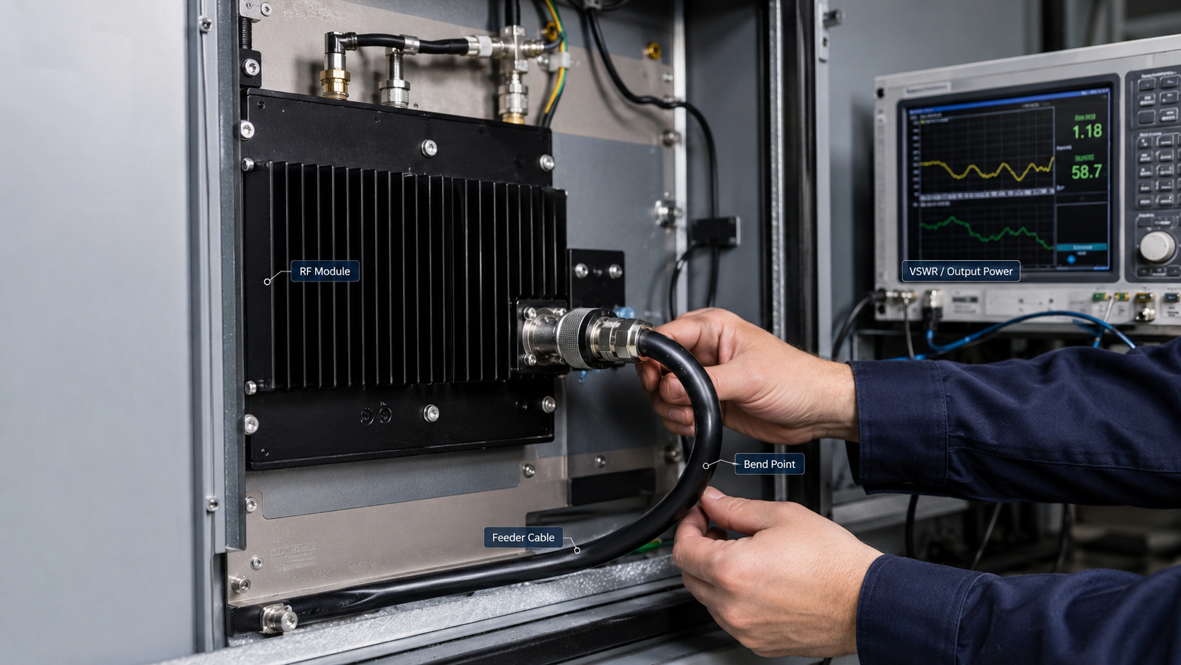
RF cable bending can cause power loss and field performance changes in RF Power Amplifier systems because a tight bend, compressed cable path, or stressed connector exit can alter the RF transmission path between the amplifier and the antenna. In a vehicle-mounted C-UAS cabinet, airport perimeter system, border tower, or critical infrastructure installation, the cable is rarely installed as a short, straight laboratory connection. It may pass through cabinet walls, bend around heat sinks, share space with DC wiring, or move under vibration.
That is why RF Power Amplifier Cable Bending should be treated as part of the complete RF chain, not as a simple cable management detail. If bending creates extra loss, local impedance change, or reflected power, a healthy amplifier may appear weak, unstable, or inconsistent after installation. The solution is not to avoid every bend. The solution is to control bend radius, routing pressure, connector strain, and test conditions before blaming the RF module.
1.What Does RF Cable Bending Mean in a Power Amplifier System?
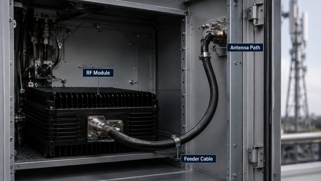
RF cable bending means the feeder cable changes direction in a way that may affect the RF path between the amplifier output and the load. In an RF Power Amplifier Cable Bending review, you are not only checking whether the cable can physically fit inside the cabinet. You are checking whether the cable routing preserves the electrical behavior needed for stable RF delivery.
A feeder cable may connect the module to an antenna, dummy load, combiner, splitter, filter, or test instrument. If the cable is forced around a sharp edge, tied too tightly, or bent near the connector body, the installation path becomes part of the performance result.
Here’s the engineering point: the cable shape can become a hidden test variable.
Where Do Bends Usually Appear?
Bends often appear where mechanical layout leaves little space for RF routing. You may not notice them during bench testing because the cable is usually relaxed and visible.
Common locations include:
- Cabinet door clearance zones
- Connector exits near the amplifier output
- Antenna bracket transitions
- Vehicle roof feed-through points
- Tower or pole routing paths
- Cable bundles fixed with tight ties
These areas deserve inspection before final RF acceptance testing.
Why Is This More Than Cable Management?
This issue matters because RF feeder cable is not the same as a DC power wire. It must preserve impedance, shielding, geometry, and mechanical stability at the same time.
Key Takeaway: RF cable bending should be reviewed as an RF path condition, not only as a neatness or installation issue.
| Installation Detail | RF Relevance | Field Risk |
|---|---|---|
| Sharp bend near output port | May disturb impedance | Reflected power rise |
| Cable pressed by cabinet door | May change shape under closure | Different test result after assembly |
| Tight cable tie | May compress dielectric structure | Local loss increase |
| Unsupported outdoor cable | May move under wind or maintenance | Intermittent fault |
| Relaxed bend radius | Preserves cable geometry better | More repeatable RF result |
This table helps you separate normal routing from routing that may change field performance.
2.What Risks Arise from Improper RF Power Amplifier Cable Bendingan Cable Appearance?
Bend radius matters because a cable can look undamaged while its RF behavior has already changed. In RF Power Amplifier Cable Bending checks, visual inspection alone is not enough, especially when the cable has been squeezed, folded, or held under stress for a long period.
The outer jacket may still look clean. The connector may still feel tight. Yet the internal geometry of the center conductor, dielectric layer, shield, and outer jacket may no longer behave like the original controlled transmission line.
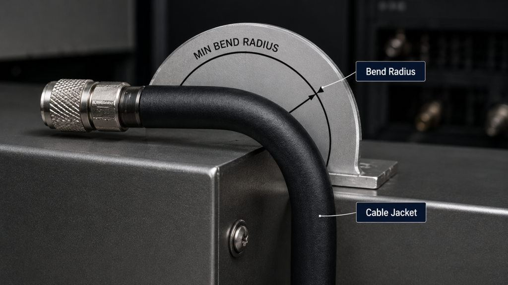
The practical risk is clear: “no visible damage” does not always mean “no RF change.”
What Can Change Inside the Cable?
A tight bend can slightly shift or compress internal layers. That matters because RF cable performance depends on controlled geometry.
Internal changes may include:
- Center conductor displacement
- Dielectric compression
- Shield braid deformation
- Partial flattening of the cable body
- Stress concentration near connector exits
The effect may be small at one frequency and much more visible at another.
Why Can the Problem Stay Hidden?
Cable bending problems often stay hidden because the cable still passes a basic continuity check. A multimeter may show connection, but RF transmission can still be affected.
Key Takeaway: A cable that looks physically acceptable may still need RF verification if it has been bent below a safe routing radius.
| Check Method | What It Finds | What It May Miss |
|---|---|---|
| Visual inspection | Jacket damage, crushed areas | Small RF impedance change |
| Continuity test | Open or broken conductor | Insertion loss variation |
| Connector hand check | Loose connector body | Internal cable stress |
| Power test | Output delivery result | Exact fault location |
| VNA or VSWR test | Reflection and mismatch | Mechanical root cause without inspection |
This table shows why cable appearance should be combined with RF testing during system acceptance.
3.What Happens Inside an RF Power Amplifier Cable When Bent
Tight bends create local impedance changes by disturbing the cable geometry that supports a controlled RF transmission path. In an RF Power Amplifier Cable Bending problem, the amplifier may still produce rated output at its port, but the feeder line can introduce a local discontinuity before power reaches the antenna.
Most RF power systems expect a stable 50Ω path. When a small cable section becomes flattened, stretched, or compressed, that section may behave differently from the rest of the cable.
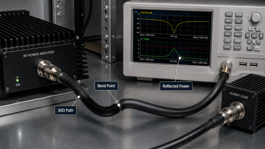
Here’s the field reality: the problem may exist in only a few centimeters of cable, but the amplifier can still see its effect.
What Is a Local Discontinuity?
A local discontinuity is a small area where the RF path no longer behaves like the surrounding cable. It can act like a minor mismatch point.
Typical causes include:
- Bend radius below cable recommendation
- Cable flattened by mounting pressure
- Connector exit bent immediately after tightening
- Cable trapped against a metal edge
- Repeated bending during maintenance
This is different from a bad cable across its full length.
How Does It Affect the Amplifier?
The amplifier does not know whether the discontinuity comes from a cable bend, connector issue, antenna mismatch, or test setup. It only sees the reflected condition at its output path.
Key Takeaway: A tight bend can create a small impedance discontinuity inside an otherwise normal feeder cable.
| Bend Condition | Possible RF Effect | System Symptom |
|---|---|---|
| Smooth large-radius bend | Minimal geometry change | Stable reading |
| Tight bend at cable middle | Local impedance change | Frequency-sensitive variation |
| Bend near connector exit | Stress at transition point | VSWR fluctuation |
| Flattened cable section | Higher insertion loss | Lower antenna-end power |
| Repeated flexing | Progressive damage risk | Intermittent alarm |
This table helps engineers look for the physical cause behind electrical symptoms.
4.How to Detect RF Power Amplifier Cable Bending Loss in Field Systems
RF output power can drop after field installation because the installed cable path may add loss that was not present during bench testing. In RF Power Amplifier Cable Bending analysis, you must compare the laboratory RF path with the real cabinet, vehicle, or tower routing path.
In the lab, the cable may be short, straight, and connected to a stable dummy load. In the field, the same cable may be bent around a bracket, pressed by a cabinet panel, or routed through a crowded cable channel.
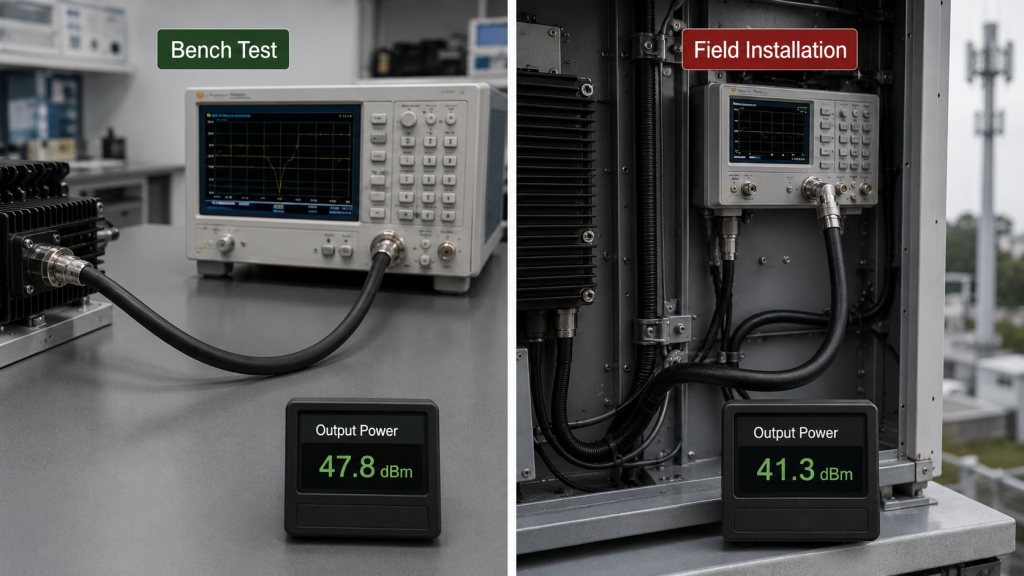
This is where system integrators should pay attention: the amplifier may not have changed, but the delivery path has.
What Changes Between Lab and Field?
The test environment and the installed environment often differ more than expected. That difference can affect antenna-end power.
Common changes include:
- Longer installed cable path
- Smaller bend radius
- Different connector orientation
- Cable pressure after cabinet closure
- Nearby heat sources or moving structures
- Different measurement point
If you only compare final power numbers, you may misread the source of the loss.
How Should You Compare Results?
Compare the same amplifier under controlled cable conditions and installed cable conditions. Record the routing state, not only the module serial number.
Key Takeaway: Field power changes may come from the installed RF path, even when the amplifier module is performing normally.
| Test Condition | Cable State | What It Proves |
|---|---|---|
| Factory port test | Controlled short path | Module output behavior |
| Bench system test | Visible cable path | Basic chain function |
| Cabinet open test | Partially installed path | Layout effect before closure |
| Cabinet closed test | Final mechanical condition | Real installed performance |
| Antenna-end test | Full RF delivery path | Actual field output result |
This table shows why field testing must match the final routing condition.
5.What Causes VSWR Issues from RF Power Amplifier Cable Bending
Cable bending affects VSWR and reflected power by creating a mismatch point somewhere inside the output path. In an RF Power Amplifier Cable Bending case, the reflected power alarm may not come from the antenna itself. It may come from a bent feeder section, a stressed connector exit, or a cable path that changes after installation.
RF Power Amplifier protection circuits respond to the reflected condition they see. They do not automatically identify whether the root cause is the antenna, connector, cable, or cabinet layout.
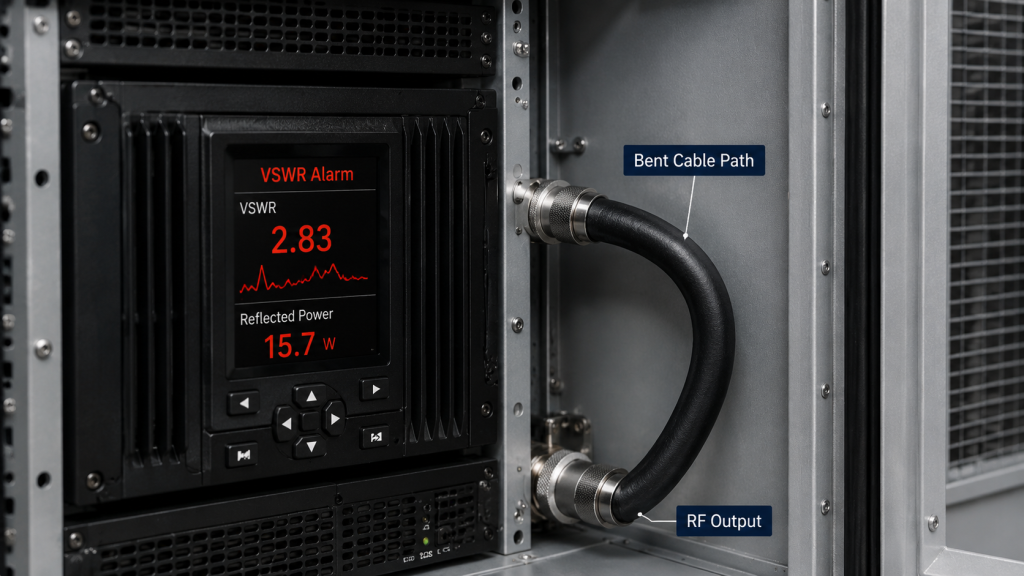
Here’s the practical risk: you may replace the wrong component if you do not inspect the cable route.
What Symptoms Point to a Bend-Related Issue?
Bend-related VSWR issues often appear inconsistent because the cable condition changes with position, vibration, or cabinet closure.
Warning signs include:
- VSWR improves when the cable is straightened
- Alarm appears after closing the cabinet door
- One installation fails while another passes
- Reflected power changes after vehicle movement
- A new cable fixes the issue without changing the antenna
These symptoms suggest that the mechanical path should be checked.
How Is This Different From Antenna Mismatch?
Antenna mismatch usually stays connected to the antenna or environment. Bend-related mismatch follows cable position and routing pressure.
Key Takeaway: A reflected power alarm may come from the bent cable path, not only from the antenna or load.
| Symptom | Possible Cable-Bend Cause | Check Method |
|---|---|---|
| Alarm after door closure | Cable compressed by panel | Test open vs closed cabinet |
| VSWR changes after movement | Cable position shifted | Inspect after vibration |
| Alarm near high band | Bend-sensitive frequency effect | Sweep across frequency |
| Passes with short test cable | Installed cable path issue | Compare cable routing |
| Intermittent reflected power | Stress near connector exit | Move cable gently while monitoring |
This table gives engineers a practical way to avoid blaming the antenna too early.
6.How to Manage High-Frequency RF Power Amplifier Cable Bending
Higher frequencies are more sensitive to cable bending because smaller physical changes can create more noticeable RF effects. In RF Power Amplifier Cable Bending reviews for C-UAS systems, this matters because many installations include 2.4GHz, 5.8GHz, and wideband ranges such as 2000–6000MHz.
A cable path that seems acceptable at a lower frequency may create more loss, ripple, or reflection at a higher frequency. This becomes more important when one platform carries several RF channels.
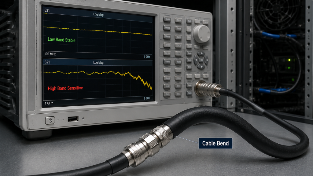
Here’s the engineering point: “it worked at one band” does not prove it works across every band.
What Makes High-Band Paths Less Forgiving?
At higher frequencies, cable geometry, connector transitions, shielding quality, and installation stress become more visible in measurements.
Sensitive points include:
- Small impedance variations
- Connector-to-cable transition quality
- Shield deformation
- Bend near antenna feed points
- Extra loss in longer routes
- Repeatability across multiple frequencies
You should not judge a high-band installation by low-band behavior alone.
Why Does This Matter for Wideband Systems?
Wideband systems may use several channels and cable paths in one cabinet. A routing problem in one band can create a weak zone even when other bands appear normal.
Key Takeaway: Higher-frequency RF paths need stricter cable bend control because small mechanical changes can produce measurable RF differences.
| Frequency Situation | Bend Sensitivity | Engineering Action |
|---|---|---|
| Low-frequency narrowband | Often more tolerant | Still avoid sharp bends |
| Mid-band RF path | Moderate sensitivity | Verify after routing |
| 2.4GHz path | Higher sensitivity | Control connector exits |
| 5.8GHz path | Higher sensitivity | Avoid compression and tight bends |
| 2000–6000MHz wideband | Frequency-dependent behavior | Sweep across full operating range |
This table supports full-band verification instead of single-point assumptions.
7.How Can Cabinet Layout Create Hidden Bend Problems?
Cabinet layout can create hidden bend problems when the mechanical design leaves too little space for RF cable routing. In an RF Power Amplifier Cable Bending review, you should inspect not only the cable, but also the cabinet geometry that forces the cable into a tight bend.
Many cable problems are not caused by careless installation. They are caused by output ports placed too close to walls, filters installed in awkward positions, or cable exits that conflict with air paths and access panels.
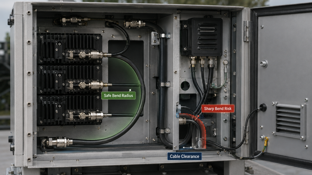
This is where system integrators should pay attention: the layout may be creating the fault before the cable is even installed.
Which Layout Details Cause Risk?
RF cables need clearance, bend radius, and strain relief. If those are not planned early, the installer may have no good routing option.
Risky layout details include:
- Amplifier output port too close to cabinet wall
- Cable forced to turn immediately after connector
- RF cable bundled tightly with DC wiring
- Door panel pressing on feeder line
- Fan or heat sink blocking routing space
- Cable exit hole placed at the wrong angle
These issues should be reviewed before production assembly.
How Can You Design Around the Problem?
Good layout leaves mechanical space for the cable’s electrical role. Treat cable routing as part of RF design, not as a final packaging task.
Key Takeaway: Cabinet layout can force cable bending problems, so routing space should be designed before final assembly.
| Cabinet Factor | Bend Risk | Prevention Step |
|---|---|---|
| Output port near wall | Immediate tight bend | Add connector clearance |
| Crowded RF bay | Cable compression | Separate RF routing channel |
| Door interference | Bend changes after closure | Test with door closed |
| Shared cable bundle | Pressure from ties | Use controlled supports |
| Poor feed-through angle | Long-term cable stress | Align exit with cable path |
This table helps mechanical and RF teams review the same layout before field deployment.
8.Why Do Vehicle and Outdoor Systems Need Extra Bend Control?
Vehicle and outdoor systems need extra bend control because the cable is exposed to movement, vibration, temperature change, maintenance, and mechanical stress after installation. In RF Power Amplifier Cable Bending checks for airport, perimeter, vehicle-mounted, or fixed-site systems, the bend is not always static.
A cable may look acceptable during installation but move under vehicle vibration, wind load, cabinet service, or repeated door closure. If the bend is close to the connector, the stress can build over time.
Here’s the field reality: a cable route that passes on day one may fail after repeated movement.
What Makes These Systems Different?
Outdoor and mobile platforms experience conditions that a lab bench does not reproduce. The cable route must survive the operating environment.
Typical stress sources include:
- Vehicle vibration
- Roof or mast movement
- Wind on exposed cable runs
- Temperature cycling
- Maintenance pull force
- Repeated cabinet opening
- Cable rubbing against brackets
These stresses can turn a bend into a long-term failure point.
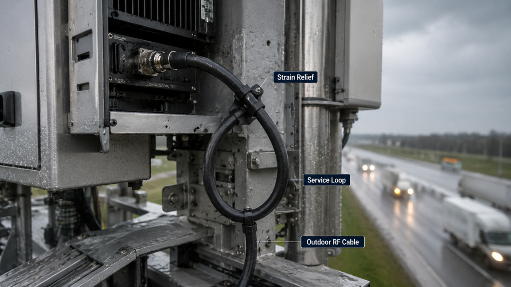
How Should You Control Long-Term Stress?
Use strain relief, routing supports, and adequate service loops. Do not allow the connector to carry cable weight or vibration stress.
Key Takeaway: In vehicle-mounted and outdoor systems, cable bending must be controlled for long-term mechanical stress, not only initial installation.
| Field Condition | Cable Risk | Practical Control |
|---|---|---|
| Vehicle vibration | Repeated flexing | Add support and strain relief |
| Outdoor wind | Cable movement | Secure with proper spacing |
| Temperature cycling | Material expansion stress | Avoid rigid over-tight fixing |
| Maintenance access | Cable pulled or twisted | Leave service loop |
| Tower routing | Abrasion and pressure | Protect contact points |
This table shows why field environment should influence cable routing decisions.
9.How to Prevent RF Power Amplifier Cable Bending Loss During Installation
Engineers can check and prevent cable-bend loss by testing the cable in the same routing condition used in the final installation. In RF Power Amplifier Cable Bending troubleshooting, you should not only remove the cable, straighten it, and test it on a bench. That may hide the exact condition causing the field problem.
The better approach is to compare controlled cable states: installed open cabinet, installed closed cabinet, alternative cable, and short verified test cable.
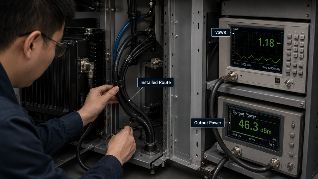
Here’s the practical point: reproduce the mechanical condition before judging the electrical result.
What Should You Inspect First?
Start with the simplest physical checks before replacing RF modules or antennas. Many routing faults are visible once you know where to look.
Check for:
- Sharp bends near connector exits
- Flattened or kinked cable sections
- Cable trapped by cabinet doors
- Ties tightened directly over coaxial cable
- Cable rubbing against metal edges
- Cable path changes after vehicle movement
- Outdoor cable hanging under tension
Document the routing state with photos during testing.
What Tests Help Confirm the Cause?
Use comparison tests that isolate the cable path from the amplifier. If the result changes with routing, the cable path is part of the fault.
Key Takeaway: Cable-bend loss should be checked under real routing conditions, not only with the cable removed from the system.
| Check Step | Purpose | Good Practice |
|---|---|---|
| Inspect bend radius | Find mechanical stress | Check full route, not only ends |
| Compare open vs closed cabinet | Find compression | Measure both states |
| Swap verified cable | Isolate cable fault | Keep same load and frequency |
| Sweep frequency | Find band-sensitive loss | Test high-frequency bands carefully |
| Record cable path | Support repeatability | Save photos and test notes |
This table gives engineers a repeatable troubleshooting path before blaming the RF Power Amplifier.
10.How Do Suppliers Reduce Cable-Bending Misjudgment?
Suppliers reduce cable-bending misjudgment by helping customers separate real amplifier performance from installation-induced RF path problems. In RF Power Amplifier Cable Bending discussions, a good supplier should not simply say the module is rated at a certain wattage. They should help you understand where that power is measured and how the installed RF path affects the final result.
This is especially important when the same module passes factory testing but appears weaker after integration. The difference may come from cable routing, connector condition, antenna match, load position, or measurement method.
Here’s the engineering value: better diagnosis protects both the buyer and the supplier from the wrong conclusion.
What Should You Ask the Supplier?
Ask for information that connects module data with system integration reality. A useful supplier can help you review the RF path, not only the power label.
Questions to ask include:
- Where was output power measured?
- What cable and load were used during testing?
- Was reflected power monitored?
- Was the test done across the full band?
- Are connector and cable routing limits discussed?
- Can the supplier support repeatable test setup guidance?
These questions reduce uncertainty during field acceptance.
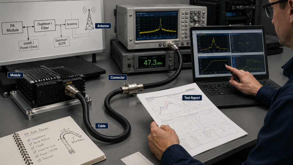
What Support Matters Most?
For wideband RF Power Amplifier modules used in C-UAS systems, cable bending should be evaluated as part of the full RF chain. The module, feeder cable, connector, antenna, and installation path work together in the final field result.
Key Takeaway: A capable RF supplier helps customers identify whether a field issue comes from the module or from the installed RF path around it.
| Supplier Support | Why It Matters | Buyer Benefit |
|---|---|---|
| Port power data | Confirms module baseline | Avoids guessing |
| Full-band verification | Shows frequency behavior | Finds weak zones |
| Reflected power monitoring | Detects load stress | Reduces field failure risk |
| Integration guidance | Connects module to system | Improves installation success |
| Repeatable test setup | Makes results comparable | Supports acceptance review |
This table shows why engineering support is part of reliable RF module sourcing.
FAQ
Can I bend RF cable if the system is low power?
Yes, but the bend still needs control. Lower power may reduce thermal and stress risk, but impedance change, insertion loss, and repeatability problems can still appear, especially at higher frequencies.
What’s the best way to check RF cable bend radius?
The best method is to follow the cable manufacturer’s bend radius guidance and verify the installed RF path with power and VSWR tests. You should test the cable in the final routing condition, not only when it is straight on a bench.
How do I know if cable bending is causing VSWR alarms?
A bend-related issue is likely if VSWR changes when the cable is moved, straightened, replaced, or tested with the cabinet door open versus closed. These symptoms suggest the cable path should be inspected before replacing the antenna or amplifier.
Can cable bending affect only some frequencies?
Yes, frequency-sensitive effects are common. A cable route may look acceptable at lower frequencies but create more loss or reflection at higher bands such as 2.4GHz, 5.8GHz, or 2000–6000MHz paths.
What’s the best prevention step during cabinet design?
The best prevention step is to reserve enough connector clearance, cable routing space, and strain relief before final cabinet layout. RF cable routing should be reviewed together with module placement, antenna ports, thermal paths, and maintenance access.
Conclusion
RF cable bending affects RF Power Amplifier field performance because the feeder cable is part of the output delivery path, not an isolated accessory. This article explained why bend radius matters, how tight bends can create local impedance changes, why antenna-end power may drop after installation, how VSWR alarms can come from the cable path, and why high-frequency, vehicle-mounted, outdoor, and cabinet-based systems need stricter routing control.
RF SKYPOWER can support system integrators with factory-direct RF Power Amplifier modules, C-UAS core components, practical RF chain awareness, and repeatable test setup thinking. If your field result changes after installation, maintenance, or cabinet closure, the right next step is not to blame one component too quickly. Review the module, feeder cable, connector, antenna, cabinet layout, and measurement point as one RF system.
For verified RF module support and engineering-focused sourcing, contact us today.
Controlled RF energy should be measured at the module, protected through the cable path, and delivered predictably in the field.