










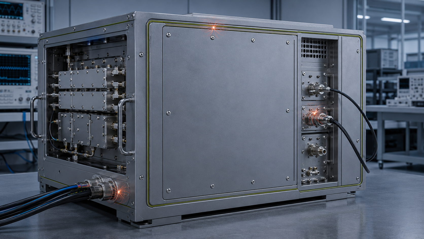
RF PA shielding improves when the weak electromagnetic boundary is identified and corrected, not when more metal is added without knowing the coupling path. A cabinet can have substantial metalwork and still show alarm flicker, detector drift, communication errors, or channel interaction if RF energy crosses a seam, connector opening, cable entry, shared harness, or poorly bonded transition.
The first decision is therefore whether the symptom follows a shielding discontinuity, a conducted or reference path, or another integration fault. Keep the operating condition controlled while you isolate that boundary, then prove the fix again with the production cover, gasket, cable routing, and required RF channels restored.
What RF PA Shielding Must Actually Control
A useful shielding boundary is the complete conductive enclosure around the RF energy that should remain contained. Depending on the module and cabinet, that boundary can include the PA housing, internal cavity walls, shield covers, cover seams, conductive gaskets, connector bodies, cable-entry hardware, cabinet panels, and removable service covers.
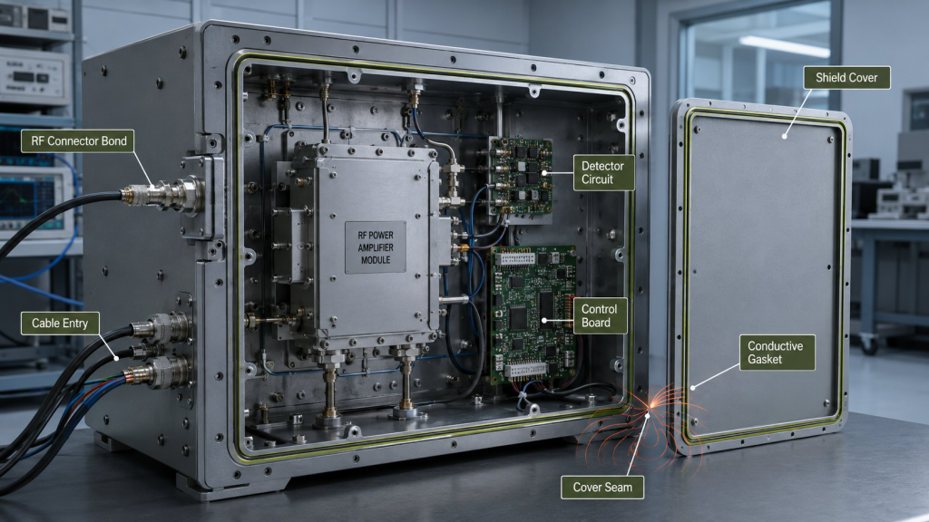
The engineering question is whether the assembled boundary remains electrically continuous at the frequencies and operating conditions that matter. A small opening, poor contact surface, or uncontrolled transition can create a more important leakage path than the broad face of a thick cover.
Typical symptoms can appear in circuits that are not the RF output path itself: detector readings move with RF state, an alarm line changes only at high output, a communication link becomes unstable, a neighboring channel behaves differently, or low-level circuitry responds to a cabinet state change. Those symptoms identify where to investigate, but they do not prove the path by themselves.
Before modifying hardware, capture a reproducible baseline and note any condition that could change the symptom. If more than one operating variable moves between checks, the comparison cannot isolate the shielding path.
Why More Metal Does Not Fix a Broken Shield Boundary
Shield thickness matters only after the dominant leakage path is understood. In assembled equipment, weak points are often transitions: an uneven seam, under-compressed conductive gasket, painted or oxidized contact surface, distorted cover, large cutout, poorly bonded panel joint, connector-shell transition, or cable shield that does not terminate cleanly at the enclosure boundary.
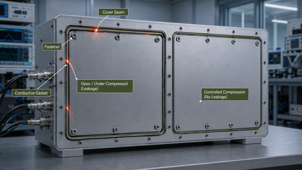
That leads to a practical inspection order. Check whether the cover seats flat, whether the gasket has continuous contact, whether conductive surfaces are clean and compatible with the intended bond, whether connector bodies are bonded to the enclosure, and whether a service cover returns to the same mechanical state after maintenance.
Fastener condition belongs in this check because uneven compression can change the electrical seam. If a cover joint changes after vibration, thermal exposure, or reassembly, use the existing RF PA fastener preload and post-stress checks to diagnose the mechanical joint rather than treating the problem as a request for thicker shielding material.
A diagnostic change is not yet an accepted fix. Pressing on a cover, temporarily bridging a seam, or rerouting one cable can identify a likely path. Acceptance still requires the intended production hardware to be restored and retested.
Where Hidden EMI Paths Form Inside a PA Cabinet
Hidden EMI paths are easier to isolate when they are grouped by mechanism rather than by symptom.
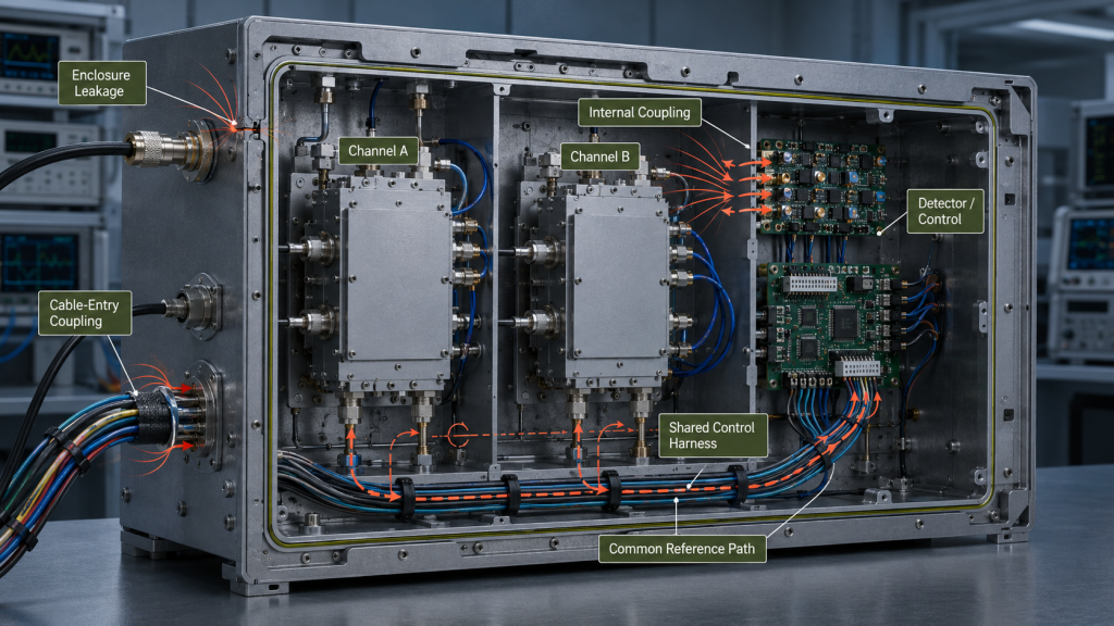
Enclosure leakage crosses openings in the conductive boundary: seams, gaskets, apertures, panel joints, connector cutouts, ventilation structures, or removable covers.
Internal field coupling occurs when high-level RF fields reach detector, bias, control, low-level input, or neighboring-channel circuitry inside the enclosure.
Cable-entry and common-mode coupling uses DC, control, alarm, communication, or shield conductors as unintended RF paths across the cabinet boundary.
Shared-path coupling appears through harnesses, cabinet metalwork, power distribution, or reference structures shared by multiple PA channels.
These mechanisms can produce similar visible symptoms. An alarm that toggles with RF output does not prove bad control logic, and a communication error does not prove firmware failure. The symptom becomes useful only when it is correlated with a controlled change in one suspected path.
For a multi-PA cabinet, preserve channel identity while troubleshooting. If the active switch, filter, output connector, or test reference plane is uncertain, complete the cabinet RF routing verification before drawing a shielding conclusion. A route error can imitate a coupling problem and needs a different corrective action.
What Shielding, Bonding, Grounding, and Filtering Each Own
These functions interact, but they do different jobs.
Shielding controls where electromagnetic fields can propagate. Bonding maintains conductive continuity across covers, panels, connector shells, and cabinet joints. Grounding defines electrical relationships such as DC return, signal reference, chassis, protective earth, and measurement reference. Filtering or decoupling limits unwanted conducted energy on DC and signal lines.
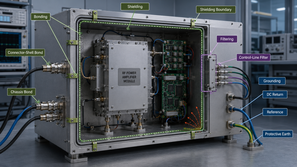
Each remedy addresses a different path. A new ground wire does not close an open RF seam. A conductive gasket does not remove common-mode energy carried through an unfiltered cable. A filter does not repair a connector shell that is poorly bonded to the enclosure.
When a symptom tracks DC current, controller reference, or the voltage between nominal reference points, verify the RF PA grounding and reference-path boundary before attributing the behavior to shielding. A reference shift can produce the same visible symptom through a different mechanism.
Use the same rule for bonding: a bond is part of the shielding boundary when it controls enclosure continuity, but a full grounding architecture still needs its own electrical definition. Keeping those jobs separate prevents a successful temporary change from being misclassified as the final root cause.
How to Define a Comparable Shielding Test Condition
Shielding behavior can change with frequency, cabinet state, channel combination, cable geometry, and thermal condition. A useful before/after comparison therefore fixes the variables that are not under test.
For a narrowband system, include the actual operating channel, relevant channel edges, and any frequency where the symptom has appeared. For a broadband or multi-band system, choose points that represent the required operating span rather than assuming one frequency can represent the entire enclosure.
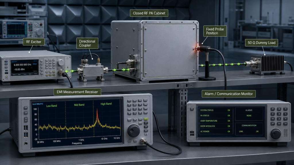
Record at least the frequency, actual RF input condition, RF output or defined power state, duty cycle, module-side Vdc and current where relevant, load condition, active channel set, temperature or stabilization condition, cover state, cable routing, measurement position, and the alarm/communication/monitor state being observed.
If the PA is being exercised into a bench load, the load setup must also be defined. The dummy-load testing boundary is useful when the question is whether the RF source/load chain is controlled before cabinet-level EMI behavior is interpreted.
The comparison is valid only while the relevant baseline remains aligned. If the probe position, cable route, output state, or active channel changes at the same time as the seam or gasket, the result can suggest a path but cannot isolate it.
How to Isolate the EMI Path Without Creating a False Fix
Before opening the enclosure or changing a physical or electrical boundary, follow the applicable equipment isolation and discharge procedure for the PA and cabinet. Removing RF drive is necessary but does not by itself isolate energized DC circuits or stored energy. Any diagnostic work that intentionally requires an energized open cover belongs only in an approved contained setup with a procedure designed for that condition; otherwise isolate the equipment before hands-on changes, restore the final assembly, and repeat the required closed-cover operating test afterward.
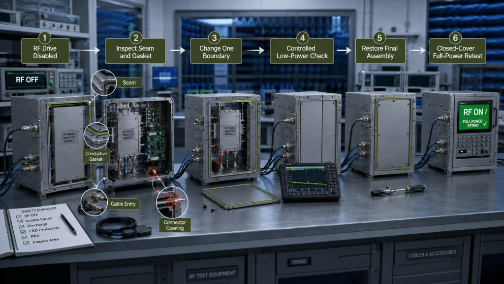
A useful isolation sequence is:
- Reproduce and record the original symptom under a defined condition.
- Disable RF drive and complete the required electrical isolation and discharge steps before hands-on opening or hardware changes.
- Inspect the suspected seam, gasket, connector opening, cable entry, and bonding surface.
- Change one physical or electrical boundary only.
- Compare the symptom under a controlled diagnostic condition.
- Restore the intended cover, gasket, fasteners, cable route, and cabinet state.
- Repeat the required closed-cover test at the defined operating condition.
- Confirm whether the result remains stable after the thermal state relevant to the project is reached.
Use the symptom as a routing clue rather than a diagnosis:
| Observed behavior | Candidate path(s) to investigate | Discriminating check |
|---|---|---|
| Alarm or detector value changes only with RF output | Field coupling, RF-dependent supply/reference shift, or another RF-state-dependent electrical effect | Use RF-off/RF-on only to establish correlation; then change one suspected coupling boundary while monitoring the relevant DC/reference conditions and keeping the measurement point fixed |
| Communication becomes unstable at high RF output | Harness, cable-entry, or common-mode coupling | Hold RF state constant and compare one cable-entry or routing boundary at a time |
| One frequency produces a repeatable noise rise | Seam, aperture, cavity, or transition behavior | Repeat at defined frequency points with fixed probe position and cabinet state |
| Closing the cabinet changes the symptom | Cover contact, seam, or internal field distribution | Compare the controlled diagnostic state with the fully restored production closure |
| A second PA channel causes detector drift | Channel-to-channel or shared-path coupling | Compare single-channel and specified simultaneous-channel conditions |
| Fault appears after service work | Gasket, fastener, connector-shell, or cable-route change | Inspect the serviced boundary and repeat the same closed-cover condition |
If the symptom remains after the coupling path is controlled and the question turns to pin logic, register meaning, alarm semantics, or protocol behavior, verify that the RF PA control interface matches its defined pin logic, register meanings, alarm semantics, and protocol rules. Those checks determine whether the remaining fault is an interface-definition problem rather than an EMI path.
How to Verify Multi-Channel and Thermal Interaction
A cabinet that is stable with one PA active can behave differently when the required channel combination is operating. The test plan should therefore move from individual channels to the simultaneous combinations that the system must actually support.
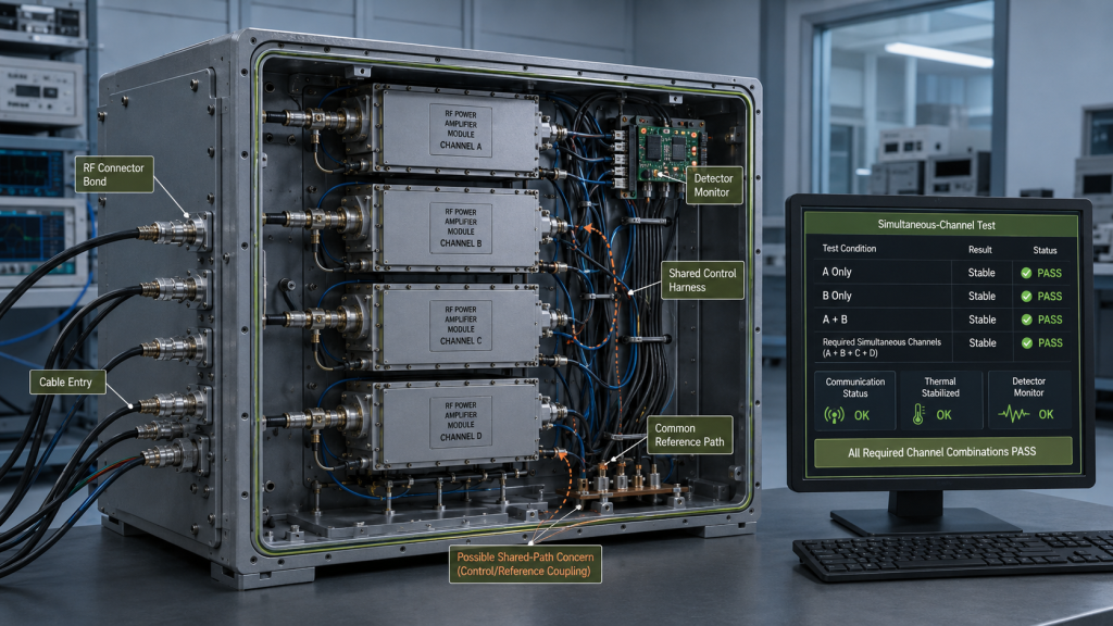
Monitor the same decision-relevant signals during each condition: RF output state, detector values, alarms, communication stability, controller resets, neighboring-channel behavior, protection actions, and the temperature or thermal state that can change the cabinet condition. Keep the final cover and intended cable routing in place for the acceptance run.
Single-channel results are only a baseline. Cabinet approval depends on whether the required single and simultaneous-channel conditions remain stable under comparable settings and whether any first change is repeatable when the channel combination changes.
Treat any illustrated pass/fail matrix as a test-sequence template, not as evidence for a specific unit. Acceptance requires results recorded from the applicable assembly under its defined conditions.
What Evidence Is Strong Enough for Acceptance
A supplier statement that the module has a metal housing is not shielding evidence by itself. Acceptance should connect the physical boundary to a reproducible operating result.
Useful evidence can include the housing and shield-cover arrangement, seam and aperture locations, gasket or conductive-foam specification where used, intended compression/contact condition, connector-shell and cable-entry treatment, cabinet bonding points, relevant cable routing, defined frequency points, RF operating state, active channel combinations, thermal condition, monitored control/detector behavior, and the final closed-cover state.
For projects that include maintenance, vibration, or other mechanical stress in the qualification plan, add the relevant post-stress inspection and reassembly retest. Do not generalize a pre-stress result into proof of post-stress continuity without that evidence.
A practical acceptance statement is:
With the intended production covers, gasket/contact surfaces, connector and cable entries, cable routing, bonding and defined grounding interfaces installed, the cabinet must show stable decision-relevant RF, detector, alarm and communication behavior at the required frequencies and channel combinations under the specified operating condition.
That statement still needs project-specific limits and evidence. It does not create a universal shielding-effectiveness number, EMC compliance claim, or delivered-unit guarantee.
What to Define Before RFQ and Mechanical Freeze
Shielding becomes expensive to correct after connector locations, service covers, cable entries, and cabinet geometry are frozen. The RFQ should therefore define the conditions needed to review the boundary before those mechanical decisions are locked.
Include the required frequency points or span, RF output condition, duty cycle, module count, simultaneous-channel combinations, housing/cavity arrangement, shield-cover and seam design, gasket/contact requirement where applicable, connector openings, DC/control cable entries, cabinet bonding interfaces, grounding boundary, intended RF and control cable routing, closed-cover test condition, and the acceptance evidence expected after assembly or service.
Also state what must be traceable to the tested assembly. A drawing or representative sample can support a design decision, but it should not be described as evidence for every delivered serial number unless the agreed inspection and test plan establishes that scope.
For an RFQ involving RF power amplifier modules, send the operating bands, required output condition, duty cycle, enclosure constraints, connector and cable-entry layout, channel combinations, and shielding acceptance evidence together. That gives the module and cabinet interfaces one engineering boundary instead of leaving EMI control to a late mechanical fix.
Conclusion
Improving RF PA shielding means identifying the boundary that carries the unwanted coupling and correcting that boundary under controlled conditions. A temporary improvement is diagnostic evidence only; acceptance requires the intended production geometry restored and the closed-cover result repeated across the required frequencies, channel combinations, and thermal condition.
If the restored enclosure cannot reproduce the stable result, hold the shielding decision and continue path isolation. Do not approve the cabinet from metal thickness, a single-frequency check, or an open-cover result.