










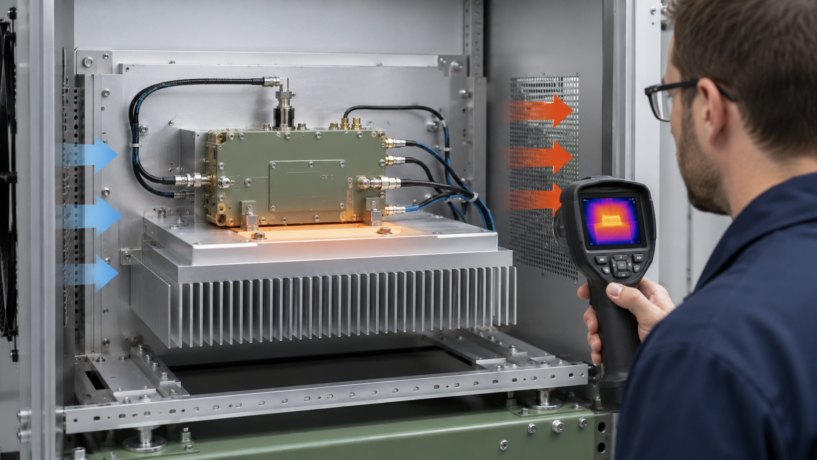
RF PA heatsink design should be approved from a defined heat load and installed thermal path, not from visible size, weight, or aluminum thickness. A large heatsink can still run hot when heat does not spread into the base, the module-to-heatsink contact is poor, or the installed airflow misses the fins.
For RF Power Amplifier Modules, the practical question is whether the proposed heatsink can remove the required heat with the actual baseplate, interface material, orientation, airflow, ambient temperature, duty cycle, and RF operating condition. If those boundaries are still undefined, a drawing or a short bench test cannot prove the final cooling result.
If the project is still defining the complete thermal path from device dissipation through cabinet cooling, start with the RF PA thermal management guide. Once that wider boundary is known, heatsink approval depends on whether the proposed base, interface, fin geometry, and installed cooling condition can keep the PA stable at hot state.
What an RF PA Heatsink Must Prove Before Integration
The external heatsink is one part of the thermal path. Heat may pass through the RF device and package, PCB or carrier, an internal spreader, the module baseplate, the thermal interface, the external heatsink, and finally the surrounding air or another controlled cooling boundary.
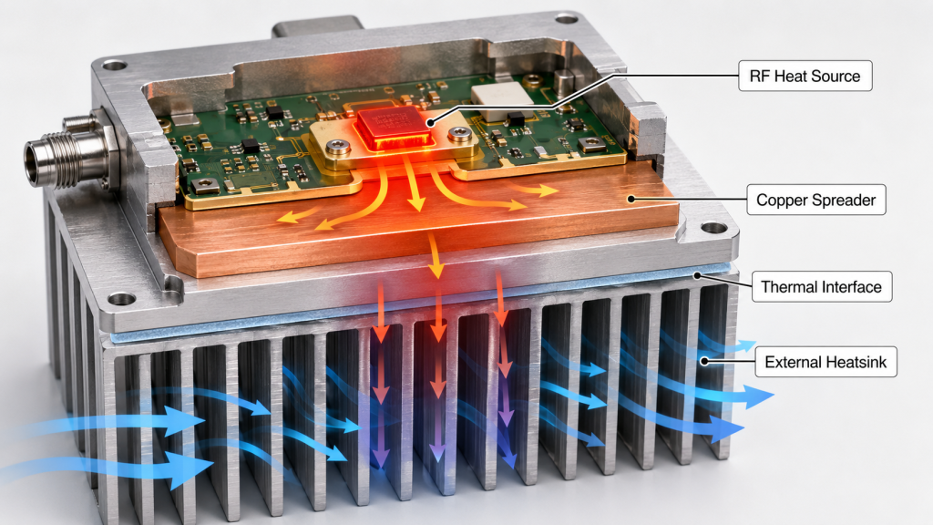
A problem at any one of those transitions can make the external heatsink look worse than it is. A large external heatsink can also hide a weak upstream path during a short test without fixing it.
The first input is the heat that the cooling path must remove under the same operating condition used for RF acceptance. A useful engineering estimate is:
Heat to remove ≈ total DC input power + net RF input power − net RF output power
Use DC input measured at the PA module supply terminals, net RF input measured at the defined PA input reference plane, and net RF output corrected to the defined PA output reference plane under the same frequency, power state, duty cycle, channel condition, and averaging interval. When reflected power is material, calculate net input as incident minus reflected power and net output as forward minus reverse power; do not use incident or forward power alone. The simplified Pdc − Pout,net form is valid only when net RF input is negligible for the stated boundary and operating condition. For pulsed or duty-cycled operation, compare time-averaged DC input, net RF input, and net RF output over the same interval rather than mixing peak and average values. Include separately powered auxiliary dissipation in this heatsink load only when that heat actually enters the thermal boundary being sized; cabinet or fan power rejected elsewhere should remain outside the module-heatsink estimate.
When efficiency, PAE, drain efficiency, back-off, or waveform changes the dissipation estimate, calculate RF PA heat load from a defined electrical boundary before sizing the heatsink, and keep DC input, RF output, and the averaging basis consistent.
A preliminary thermal-resistance boundary can then be written as:
Required total thermal resistance ≤ allowable temperature rise ÷ heat to remove
That expression is only useful when both temperature reference points are defined. “Ambient to baseplate,” “cabinet inlet to module case,” and “heatsink inlet air to a monitored device location” are different boundaries and cannot be compared as if they were the same number.
A heatsink therefore has to prove four things before integration is frozen: the heat-load input is credible, heat can reach the heatsink, heat can leave the heatsink under the installed cooling condition, and the hot-state RF result remains acceptable.
Why a Bigger Heatsink Can Still Fail at Full Load
More metal can help, but size alone does not prove steady-state cooling capacity.
A heavier heatsink usually adds thermal mass. Thermal mass changes how quickly temperature rises. Thermal resistance determines the temperature difference needed to move a given heat flow once the system approaches steady state. A large block can therefore warm more slowly during the first few minutes and still settle at an unacceptable temperature later.
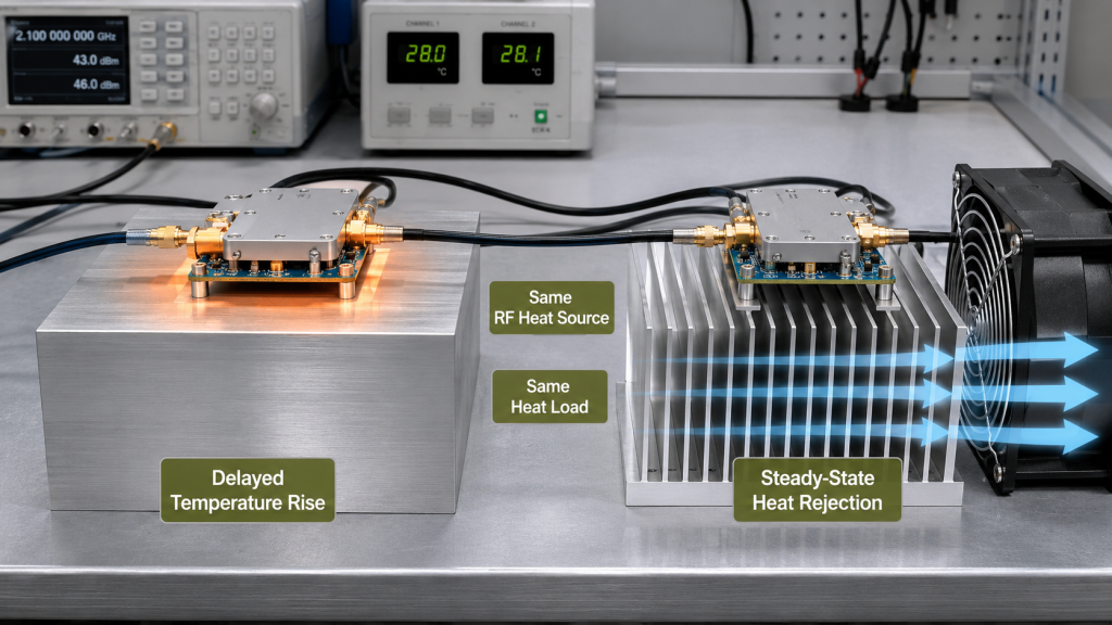
Short tests can be misleading because the assembly may look stable while the heatsink is still absorbing energy. During a longer run, temperature can continue rising until RF output changes, current changes, a protection threshold is reached, or the surrounding cabinet air becomes too hot.
A larger heatsink may also add fin area that the system never uses effectively. Extra fins provide little benefit when the base does not spread heat into them, the mounting contact is uneven, or most of the cooling air bypasses the fin channels.
Judge the heatsink by where the dominant thermal resistance sits under the intended operating condition, not by dimensions alone.
For a meaningful test, continue until the defined stabilization criterion is reached, the specified duration is completed, or a defined temperature, RF-output, current, or protection boundary is reached. “It stayed cool for five minutes” is not enough unless five minutes is itself the approved test condition.
How to Separate Heat Spreading From Heat Rejection
A heatsink problem becomes easier to diagnose when local heat spreading and final heat rejection are treated as separate mechanisms.
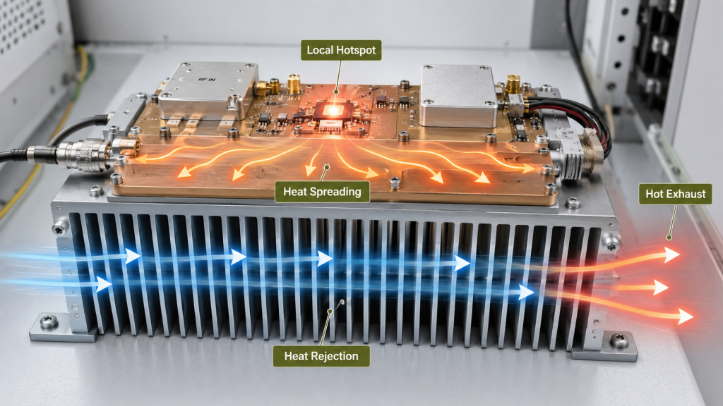
Weak heat spreading usually produces a large temperature gradient. One area near the heat source becomes much hotter while distant parts of the base or fins remain relatively cool. Adding fin area far from the hotspot may change little because the heat is not reaching that area efficiently.
Weak heat rejection looks different. Heat reaches much of the heatsink, but the assembly cannot reject it fast enough to the surrounding cooling boundary. The whole base or fin field becomes hot, inlet and outlet air temperatures climb, or the closed cabinet performs much worse than the open bench.
Those two cases need different corrections. More fins do not repair a poor local spreading path, and a thicker spreader does not fix a cabinet that recirculates hot air.
A practical comparison should include temperature distribution across the baseplate and heatsink, inlet and outlet air temperature where relevant, the response to a controlled airflow change, the response to an interface change, and the corresponding hot-state RF output and DC input.
Use the pattern as a diagnosis aid, not as proof by itself. A hot corner can come from spreading, contact, local airflow, measurement placement, or another boundary. Change one relevant condition at a time and keep the RF operating point comparable.
How to Verify the Baseplate-to-Heatsink Interface
Even a suitable heatsink can fail when the mounting interface is inconsistent.
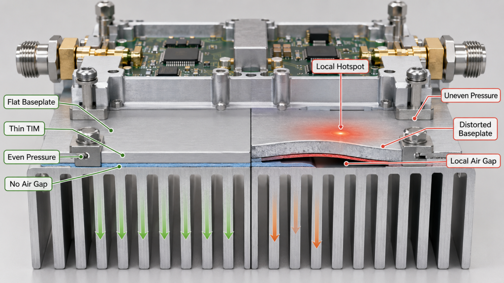
The design should define the contact area, mounting-surface flatness, hole pattern, fastener sequence or pressure requirement, approved interface material, and the allowed condition after assembly or reassembly. The purpose is to create repeatable thermal contact without distorting the module or using the interface material to compensate for a poor mechanical fit.
Thermal grease or a pad fills microscopic gaps; it does not turn a visibly uneven joint into a controlled heat path. Excessive interface thickness adds conduction distance. Incomplete coverage can leave dry regions. Uneven pressure can create a hot edge while the rest of the heatsink appears normal.
For heatsink approval, the interface condition must be controlled well enough that contact quality is repeatable between assemblies. Control RF PA thermal-grease application by defining the allowed quantity, coverage, cleanliness, compression, and reuse state before comparing thermal results between assemblies.
The evidence should still identify what was assembled: the baseplate and heatsink surfaces, the approved interface material, the mounting method, and whether the final hot-state test was performed before or after any disassembly. If the assembly is removed and rebuilt, do not assume the earlier thermal result still represents the new joint.
How Fin Geometry Must Match the Installed Cooling Boundary
Fin geometry only works when it matches the actual cooling method.
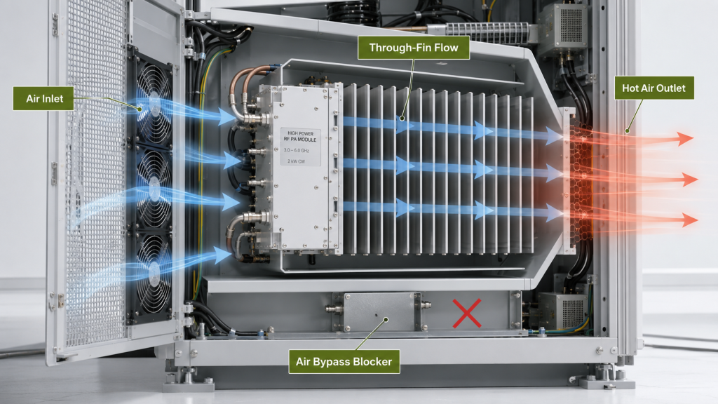
Natural convection, forced air, ducted airflow, a cabinet fan, and a controlled cooling plate impose different boundaries. For forced air, useful fin area depends on whether air can enter the channels, travel through the intended fin depth, and leave without excessive bypass or recirculation.
Closely spaced fins can increase surface area while also increasing flow resistance. A fan with an impressive free-air rating can move much less air once filters, grilles, narrow inlets, cable bundles, neighboring modules, and the heatsink itself add pressure loss.
For the heatsink decision, confirm the fin direction, relevant clearances, whether air actually passes through the fin field, whether hot exhaust can return to the inlet, and whether a neighboring module changes the inlet condition. A fan’s free-air rating does not prove installed through-fin flow. When pressure loss, restriction, or recirculation is still uncertain, verify RF PA cabinet airflow under the installed inlet, outlet, filter, grille, cable, and neighboring-module restrictions before accepting the heatsink result.
Multi-PA cabinets need one extra boundary: do not use a single-module result to approve a shared thermal condition unless the simultaneous heat load and inlet temperature seen by each module are represented. If modules share one base or one heated air path, treat cross-heating as a separate system-level question.
The heatsink drawing is therefore incomplete without the installed cooling condition. Fin dimensions that work on an open bench may not produce the same result behind a cabinet wall, filter, grille, or adjacent PA.
How to Validate the Heatsink Under Hot-State RF Load
The acceptance test should reproduce the final mechanical stack closely enough that the result answers the integration question.
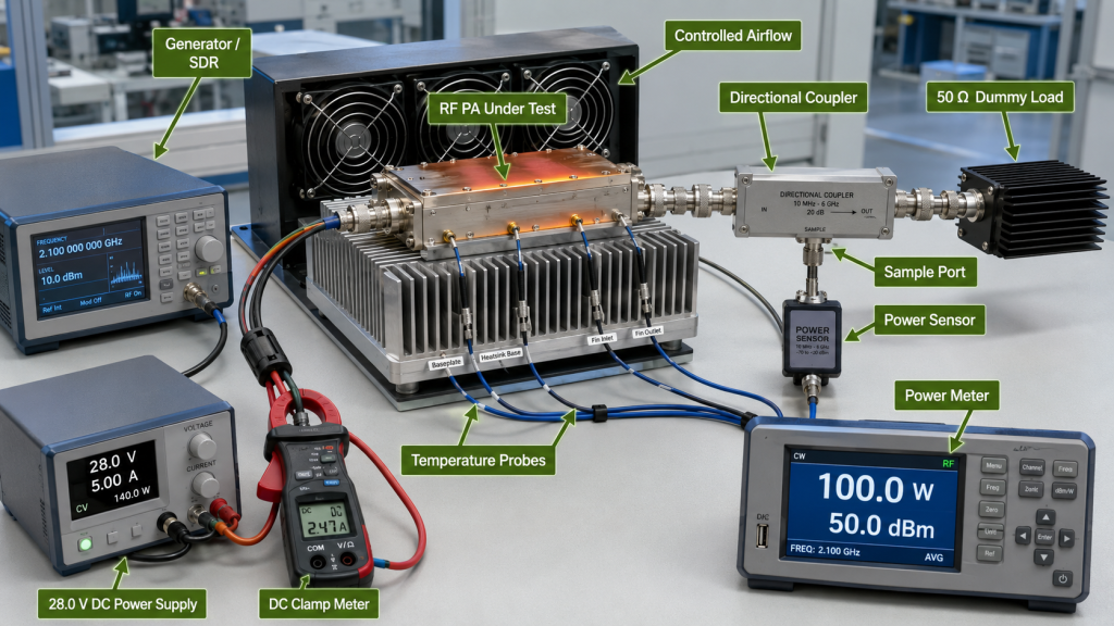
Use the intended module, baseplate, interface material, heatsink, fasteners, orientation, and cooling condition. Record a cold baseline, operate at the required frequency and RF output with the defined DC input and duty cycle, and continue until the approved stabilization or duration condition is reached.
A compact validation sequence is:
- Assemble the final thermal path and record the mounting condition.
- Set the intended orientation and installed cooling condition.
- Record cold-state RF output, Vdc, Idc, relevant temperatures, and alarm status.
- Run the required RF condition long enough to meet the defined stabilization or duration rule.
- Record hot-state RF output, Vdc, Idc, the same temperature locations, and alarm/protection status.
- Repeat the critical frequency, load, or channel condition if heat generation changes materially.
- Recheck in the final cabinet condition before approving the mechanical design.
Temperature evidence must name the measurement location. A case temperature, baseplate temperature, heatsink-center temperature, heatsink-edge temperature, inlet-air temperature, and internal device monitor do not represent the same reference point.
Cold and hot RF results are comparable only when the operating point, measurement locations, and stabilization rule are aligned. If soak duration or stabilization is unresolved, align the RF PA thermal-soak verification so both states use the same operating point, measurement locations, and stabilization rule; the heatsink decision must still represent the final mechanical and cooling boundary.
One universal heatsink temperature limit should not be copied across projects. The pass/fail boundary must come from the applicable module and system requirement and state the monitored location, ambient or inlet condition, RF operating point, duration, and protection behavior.
What Evidence Should Be Required Before RFQ Approval
A heatsink statement is useful only when it can be traced to the configuration that produced the result.

Before mechanical integration is locked, define at least the operating frequency or band, target RF output, Vdc and Idc boundary, duty cycle, estimated heat load, ambient or inlet-air condition, module orientation, heatsink responsibility, base/contact geometry, interface-material boundary, fin direction, installed cooling method, cabinet clearance, critical neighboring-module condition, hot-state duration or stabilization rule, monitored temperature locations, RF-output limit, alarm/protection boundary, and the required report format.
The report should identify the exact assembly that was tested. When the project requires unit-level traceability, link the result to the module or assembly S/N and preserve the mounting and cooling condition used for the result. A reference-heatsink test can still be useful, but it must identify enough of the reference drawing, interface, orientation, airflow, ambient condition, and duration for the integrator to decide whether it is comparable with the final installation.
A practical acceptance requirement is:
With the RF PA installed on the defined heatsink and mounting interface, under the required orientation, ambient or inlet-air condition, cooling boundary, RF output, DC input, and duty cycle, the assembly shall maintain the project-specified hot-state RF output, current, monitored-temperature, and protection limits for the required duration.
The numerical limits come from the actual project evidence. One supplier bench result does not establish a universal thermal rating.
If the integrator cannot yet define the heat load, interface, airflow/cooling boundary, temperature reference points, or hot-state pass criteria, the correct result is HOLD. Request the missing boundary instead of approving the heatsink from size, weight, or a short cold test.
Conclusion
An RF PA heatsink is ready for integration only when the required heat load, the path into the heatsink, the installed cooling boundary, and the hot-state acceptance result are all defined and repeatable. A larger or heavier heatsink may delay temperature rise, but it does not by itself prove lower steady-state temperature.
Before freezing the mechanical design, repeat the hot-state test with the final mounting and cooling boundary. Approve the heatsink only if the PA remains within the project-defined RF, DC, temperature, and protection limits; otherwise keep the design on hold and request the missing evidence.
For an engineering review, send our RF engineering team the heatsink drawing, the evidence defined above, and any unresolved installation or hot-state conditions.