










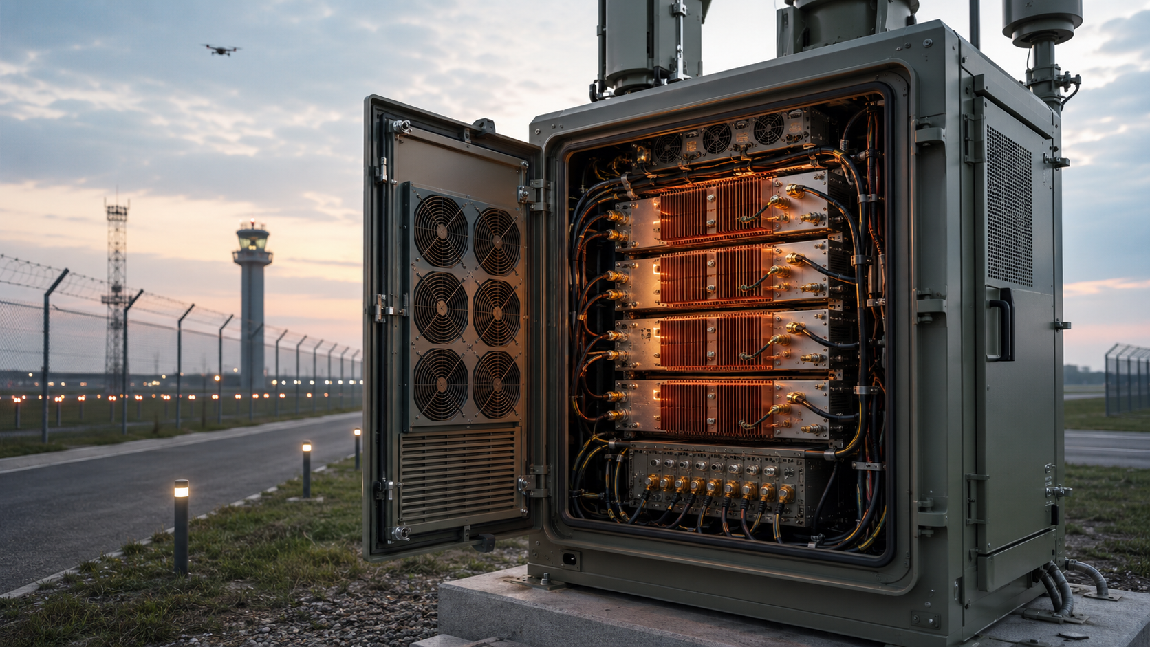
RF PA heat load is often underestimated even when the supplier provides an efficiency percentage. A cabinet engineer may see a 100 W RF output rating and a 50% efficiency claim, then assume the cooling requirement is already obvious.
But that percentage may describe drain efficiency, PAE, module DC-to-RF efficiency, or a different electrical boundary. It may exclude drivers, converters, control electronics, simultaneous PA channels, and losses that become important only after the cabinet is closed.
How many watts must the cabinet actually remove—and what evidence proves that the installed cooling path can remove them continuously?
1. How Much RF PA Heat Load Does the Electrical Boundary Create?
RF PA heat load is the power that remains as dissipation inside a defined electrical boundary after useful RF and other exported power leave that boundary.
Before calculating heat, identify whether the boundary covers:
- A final transistor stage
- A complete PA module
- A driver and PA assembly
- A multi-channel RF subsystem
- The complete cabinet
A percentage without a named electrical boundary cannot define the cooling requirement.
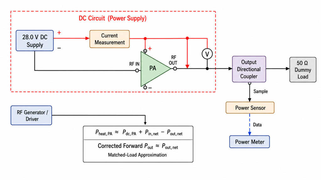
Start With Actual Electrical Input Power
For one DC rail:
Pdc = Vdc × Idc
For multiple DC rails:
Total Pdc = Σ(Vi × Ii)
Use voltage and current measured for the actual operating state. Do not substitute:
- Nominal supply voltage
- Power-supply setpoint
- Current limit
- Catalogue current
- Data from another PA sample
- Cold-state current combined with hot-state Pout
For a 28.0 V PA module, Vdc should normally be measured at the approved module-terminal reference point under load.
Use Net RF Power at the Approved Boundary
For a defined PA-module boundary:
Pheat,PA ≈ Pdc,PA + Pin,net − Pout,net
where:
Pdc,PAis total electrical power entering the PA boundaryPin,netis net RF power entering the approved input planePout,netis net RF power leaving the approved output planePheat,PAis approximate steady-state dissipation inside the boundary
Under well-matched conditions, incident Pin and forward Pout may be suitable practical approximations.
When mismatch is material:
Pin,net = Pincident,in − Preflected,in
Pout,net = Pforward,out − Preverse,out
Forward power alone should not be treated as net RF output when reflected power is significant.
All RF readings must use:
- Matching reference planes
- Matching sign conventions
- Linear units such as watts
- Applicable cable, connector, coupler, and attenuator corrections
- The same operating interval as Vdc and Idc
When Pin is small compared with Pout, engineers may state the simplified approximation:
Pheat,PA ≈ Pdc,PA − Pout,net
The simplification should not be applied silently.
The complete RF PA PAE measurement boundary should be verified before a quoted percentage is used in a heat calculation.
Calculate Heat Directly From Module Efficiency
For module DC-to-RF efficiency:
ηmodule = Pout,net / Pdc,module
Therefore:
Pdc,module = Pout,net / ηmodule
and:
Pheat,module ≈ Pout,net × (1 / ηmodule − 1) + Pin,net
When Pin is negligible:
Pheat,module ≈ Pout,net × (1 / ηmodule − 1)
Efficiency must be entered as a decimal:
50% = 0.5040% = 0.40
Do not enter 50 where the equation requires 0.50.
Calculate Heat From PAE
PAE is defined as:
PAE = (Pout,net − Pin,net) / Pdc
Rearranging:
Pdc = (Pout,net − Pin,net) / PAE
The corresponding PA-boundary dissipation is:
Pheat,PA ≈ Pdc × (1 − PAE)
or:
Pheat,PA ≈ (Pout,net − Pin,net) × (1 / PAE − 1)
This relationship is valid only when PAE, Pin, Pout, and Pdc use the same DUT boundary and operating point.
Calculate Final-Stage Heat From Drain Efficiency
For a final-stage drain boundary:
ηdrain = Pout,stage / Pdc,drain
A practical stage-dissipation estimate is:
Pheat,stage ≈ Pdc,drain × (1 − ηdrain) + Pin,stage,net
or:
Pheat,stage ≈ Pout,stage × (1 / ηdrain − 1) + Pin,stage,net
Drain efficiency may exclude:
- Internal or external driver losses
- Control and bias rails outside the drain boundary
- DC-DC converter loss
- Cooling hardware
- Other module loads
It should not be used directly as complete module or cabinet efficiency.
Match the Formula to the Efficiency Metric
| Efficiency Metric | Practical Heat Relationship | Boundary Warning |
|---|---|---|
| Drain efficiency | Pdc,drain × (1 − ηdrain) + Pin,stage | Covers only the stated final-stage drain boundary |
| PAE | Pdc × (1 − PAE) | External driver DC loss is not automatically included |
| Module DC-to-RF efficiency | Pout × (1/ηmodule − 1) + Pin | Include all DC rails inside the module boundary |
| System DC-to-RF efficiency | Use complete-system power balance | Does not show where individual losses occur |
The PAE vs drain efficiency decision boundary should be defined before percentages from different suppliers are compared or converted into heat.
2. Why Can the Same Efficiency Percentage Produce Different Heat?
Efficiency is a ratio. It does not state the actual number of watts the cooling system must remove until the associated power level and electrical boundary are known.
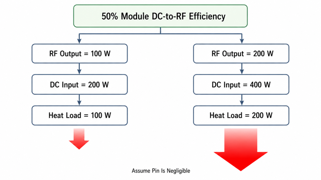
The Same Percentage Can Represent Different Heat Loads
Assume 50% module DC-to-RF efficiency and negligible Pin.
At 100 W RF output:
Pdc = 100 W / 0.50 = 200 W
Pheat ≈ 200 W − 100 W = 100 W
At 200 W RF output:
Pdc = 200 W / 0.50 = 400 W
Pheat ≈ 400 W − 200 W = 200 W
Both operating points show 50% efficiency, but the second creates approximately twice the heat.
The Same Percentage May Use Different Boundaries
Supplier A may quote 50% drain efficiency based only on the final-stage drain rails.
Supplier B may quote 50% module DC-to-RF efficiency based on:
- Final PA stage
- Internal driver
- Bias rails
- Control electronics
- Internal DC conversion
The percentages are identical, but the included losses are not.
A cabinet calculation must identify what each percentage includes before using it.
Frequency and Power Back-Off Can Change Dissipation
RF PA heat may change with:
- Frequency
- Band edge
- Output level
- Power back-off
- Gain setting
- Required Pin
- Load mismatch
- Module-terminal voltage
- Thermal state
At reduced RF output, DC input may not fall proportionally. The PA can therefore produce less RF power while still dissipating substantial heat.
When a project uses multiple output levels, RF PA efficiency at power back-off should be assessed separately.
Waveform and Duty Cycle Change Average Heat
A simplified two-state estimate is:
Average Heat ≈ D × Pheat,on + (1 − D) × Pheat,off
where D is duty cycle expressed as a decimal.
This estimate is appropriate only when:
- RF-on power is defined
- RF-off or standby power is defined
- Transition losses are negligible or included
- The operating sequence is repeatable
- The average represents the required mission interval
Long bursts, changing current with temperature, rapid power switching, or multiple overlapping channels may require a time-resolved power profile instead of one duty-cycle percentage.
Efficiency Is Not the Failure Mechanism
The correct engineering chain is:
Operating Point → Dissipation → Temperature Rise → Electrical or Protection Response
Higher dissipation may contribute to:
- Bias shift
- DC voltage drop
- Gain change
- Output reduction
- Approved derating
- Alarm activity
- Shutdown
An efficiency percentage alone cannot predict these outcomes without the thermal path and operating limits.
3. How Does RF PA Heat Leave the Cabinet?
Calculating dissipation answers how much heat is created.
The next question is whether the installed thermal path can move that heat to the external environment.
A typical path is:
Semiconductor Junction → Package → Module Baseplate → Thermal Interface → Heatsink → Cabinet Air → External Environment
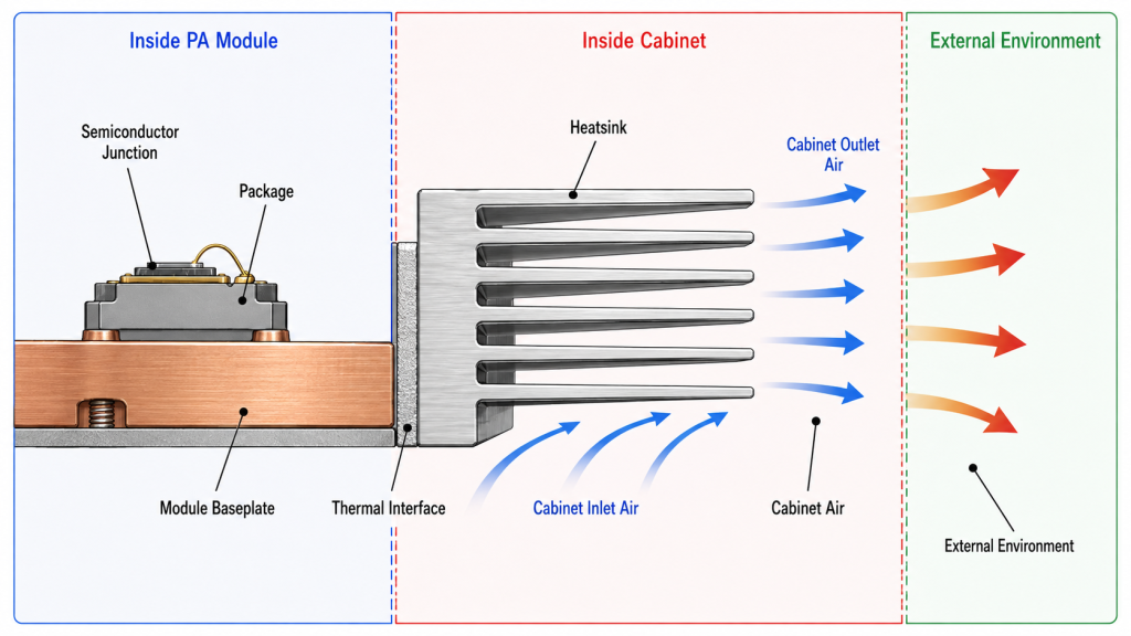
Thermal Resistance Applies to a Defined Path
For one dominant heat source and a defined steady-state path:
ΔT ≈ Pheat × Rθ,path
where:
ΔTis the temperature rise between two stated locationsPheatis the heat passing through that pathRθ,pathis the thermal resistance between the same locations
This relationship should not be extended blindly to an entire multi-source cabinet.
Multiple PAs, converters, power supplies, airflow zones, and local hotspots may require:
- A thermal-resistance network
- CFD analysis
- Representative closed-cabinet testing
- Distributed temperature measurements
The Baseplate Is Not the Final Cooling Boundary
A PA baseplate-temperature requirement assumes the cabinet can maintain that condition.
The installed design still needs:
- Flat mounting surface
- Approved mounting pressure
- Controlled thermal-interface thickness
- Adequate heat spreading
- Suitable heatsink capacity
- Effective airflow
- A route for heated air to leave the enclosure
After the heat load is established, the RF PA thermal management integration budget should connect module dissipation to the controlled temperature point, mounting boundary, cooling reference, and hot-state validation.
Once the heat load is known, an RF PA heatsink design check should verify that the external base, interface, fin geometry, and installed cooling boundary can carry that load before mechanical integration is locked.
Free-Air Fan CFM Does Not Prove Installed Airflow
Installed airflow can be reduced by:
- Filters
- Grilles
- Fin pressure drop
- Cable bundles
- Internal partitions
- Dust loading
- Air bypass
- Hot-air recirculation
- Nearby modules blocking the flow path
The complete RF PA cabinet airflow should be evaluated in the installed enclosure.
Air-Side Heat Removal Can Provide a Cross-Check
When reliable airflow and air temperatures can be measured:
Premoved,air ≈ ṁair × cp × (Tout − Tin)
where:
ṁairis measured air mass flowcpis air specific heatTinis defined cabinet inlet-air temperatureToutis defined cabinet outlet-air temperature
This is a useful engineering cross-check, not a substitute for full thermal acceptance.
Its accuracy depends on:
- Real installed airflow
- Correct mass-flow conversion
- Air mixing
- Leakage
- Bypass flow
- Recirculation
- Sensor placement
- Local hotspots
Do not insert the fan’s free-air CFM into this equation as if it were the installed cabinet flow.
4. How Should Multi-Module Cabinet Heat Be Calculated?
For a multi-channel cabinet, calculate every simultaneously operating load whose dissipation enters the thermal boundary.
Do not multiply RF output ratings and call the result heat.
Illustrative Single-Module Calculation
Assume one PA module operates at:
- Vdc =
28.0 V - Idc =
8.0 A - Pin,net =
1 W - Pout,net =
100 W - CW operation
- Thermally stabilized state
DC input is:
Pdc = 28.0 × 8.0 = 224 W
PA-module dissipation is:
Pheat,PA = 224 + 1 − 100 = 125 W
The PA delivers 100 W of net RF output, while the cooling path must remove approximately 125 W from the defined module boundary.
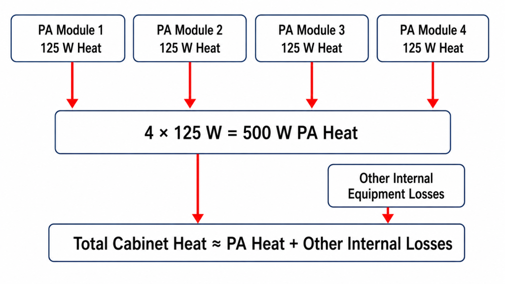
Illustrative Four-Module Calculation
If four identical modules operate simultaneously:
| Item | Per Module | Four Modules |
|---|---|---|
| 28 V DC input | 224 W | 896 W |
| Net RF input | 1 W | 4 W |
| Net RF output | 100 W | 400 W |
| PA-module dissipation | 125 W | 500 W |
| Other cabinet losses | Add separately | Add separately |
Illustrative calculation only—not a guaranteed product value.
The four PA modules alone create approximately 500 W of heat.
Additional cabinet losses may include:
- RF drivers
- SDRs or exciters
- DC-DC converters
- AC-DC power supplies
- RF switches
- Control electronics
- Monitoring electronics
- Internal distribution losses
- Fan-motor heat entering the enclosure
- Other internal electrical loads
Bottom-Up Calculation
Add each component’s dissipation:
Pheat,cabinet ≈ ΣPheat,component
This method is useful when component boundaries and losses are well defined.
Internal RF transfers must not be counted as additional cabinet heat. For example, RF power leaving a driver and entering a PA is an internal transfer, not new energy entering the cabinet.
Overall Cabinet-Boundary Calculation
For the complete cabinet:
Pheat,cabinet ≈ Pelectrical,in + Prf,in − Prf,out − Pother,useful,out
where Pelectrical,in may be:
- Actual DC input power for a DC-fed cabinet
- Actual AC input power for an AC-fed cabinet
- The sum of multiple electrical inputs
This overall balance naturally removes internal electrical and RF transfers from the final cabinet total.
Only count losses that enter the defined thermal boundary:
- Include internal power-supply loss when the supply is inside the cabinet.
- Exclude an external supply’s heat when it is physically outside the cabinet boundary.
- Include only the portion of fan-motor heat that enters the enclosure.
- Account for useful electrical power exported to equipment outside the cabinet, where applicable.
Simultaneous Operation Must Match the Real System
A four-module cabinet may operate:
- One channel at a time
- Two simultaneously
- All four simultaneously
- In alternating bursts
- At different output levels
- At different frequencies
The approved heat-load case must represent the worst-case or mission-relevant simultaneous state.
Testing one PA module does not prove a four-channel cabinet.
5. What Evidence Proves the Cabinet Can Remove the Heat?
A calculated heat load does not prove the installed cooling system can remove it continuously.
Approval requires the final or representative cabinet configuration.

Define the Test Configuration
Record:
- Closed-door enclosure condition
- Installed PA modules
- Installed thermal interfaces
- Installed heatsinks
- Final fan configuration
- Filters and grilles
- Internal cable routing
- Power supplies and converters
- Simultaneously active channels
- RF load condition
- Required ambient temperature
- Installation orientation
Open-bench operation does not prove closed-cabinet performance.
Record RF, DC, Airflow, and Temperature Together
At minimum, record:
- Frequency
- Net Pin
- Net corrected Pout
- Forward and reflected power, where applicable
- Module-terminal Vdc
- Idc
- Calculated Pdc
- Calculated dissipation
- Case or baseplate temperature
- Heatsink temperature
- Cabinet inlet-air temperature
- Cabinet outlet-air temperature
- External ambient temperature
- Fan command and actual RPM
- Fan current
- Differential pressure or approved airflow proxy, where required
- Filter condition
- Load state
- Alarm and protection state
- Test duration
- Model and serial number
A fan command showing ON does not prove the required airflow was achieved.
Define Thermal Stabilization
The test should not end only because a fixed duration has elapsed.
The acceptance plan should define a stabilization criterion, such as:
- Temperature-rise rate below an approved value for a defined interval
- Repeated readings remaining inside an approved band
- No continuing upward trend that would cross a limit during longer operation
The criterion should apply to the relevant:
- PA case or baseplate
- Heatsink
- Cabinet inlet air
- Cabinet outlet air
- Internal hotspot, where required
A single temperature snapshot is not proof of stabilization.
Preserve Hot-State RF Performance
Cooling approval requires more than acceptable temperature.
The system must also maintain:
- Minimum corrected hot-state Pout
- Approved gain range, where required
- Approved Vdc range
- Maximum Idc
- Maximum case or baseplate temperature
- Maximum heatsink temperature
- Maximum cabinet-air temperature
- Approved mismatch condition
- Required fan or airflow state
- No unapproved derating
- No unexpected alarm
- No shutdown
The full hot-state RF power derating rule should distinguish an approved limit from uncontrolled thermal output loss.
No Shutdown Is Not a Pass Criterion
A cabinet may finish the test without shutting down and still fail because:
- Temperature is still rising
- Pout falls below the approved minimum
- Idc or Vdc moves outside its limit
- Protection repeatedly reduces output
- A local hotspot exceeds its limit
- Installed airflow is below the approved condition
- The test uses fewer active channels than the real system
Cooling is acceptable only when the complete RF, electrical, thermal, airflow, and protection state remains within the approved limits.
RFQ: What Heat-Load Boundary Must Be Defined?
Specify the following before the module and cabinet configuration is approved:
| Boundary | Required Input | Required Evidence |
|---|---|---|
| RF operation | Module count, simultaneous channels, frequency, Pout, Pin, waveform, duty cycle, load | Matching hot-state RF test state |
| Electrical input | Module-terminal Vdc, Idc, included rails, AC/DC cabinet input | Measured electrical power at the approved boundary |
| Efficiency | Drain efficiency, PAE, module or system DC-to-RF efficiency | Formula, numerator, denominator, and reference planes |
| Heat calculation | Module and cabinet dissipation method | No double-counting of internal transfers |
| Cooling path | Mounting surface, interface, heatsink, fans, filters, airflow boundary | Final or representative installed configuration |
| Environment | Ambient range, enclosure state, orientation, contamination condition | Test at the approved environmental boundary |
| Acceptance | Stabilization rule, temperature limits, minimum hot-state Pout, derating and alarm rules | S/N-linked pass/fail evidence |
The heat-load and cooling boundary should be reviewed for the selected Custom RF Power Amplifier Modules configuration rather than inferred from rated RF output or one unnamed efficiency percentage.
Conclusion
The cabinet must continuously remove the total steady-state dissipation generated by every simultaneously operating load inside its thermal boundary.
For each defined PA-module boundary, calculate that dissipation from the net power balance:
Pheat,PA ≈ Pdc + Pin,net − Pout,net
If the calculation begins with module DC-to-RF efficiency, convert the percentage into actual DC input and heat:
Pheat,module ≈ Pout,net × (1 / ηmodule − 1) + Pin,net
For the complete cabinet, either add the correctly bounded losses from every PA, driver, converter, power supply, controller, fan, and other internal load, or apply an overall cabinet energy balance. Do not count internal electrical or RF transfers twice.
That total cannot be determined from rated RF output or one unnamed efficiency percentage alone.
The cooling design is acceptable only when the final closed-door configuration reaches the approved thermal stabilization criterion while:
- Minimum hot-state Pout is maintained
- Vdc and Idc remain within limits
- Case, baseplate, heatsink, and cabinet-air temperatures remain below their limits
- Installed airflow remains within the approved condition
- The required load and simultaneous-channel state are maintained
- No unapproved derating, alarm, or shutdown occurs
Do not approve the cabinet from heatsink size, free-air fan CFM, cold-bench output, one temperature snapshot, or an efficiency percentage alone.
RF SKYPOWER can review the RF PA heat-load boundary before the module and cabinet configuration is finalized.
Submit the module count, simultaneous-channel condition, required Pout, available Pin, module-terminal Vdc and Idc, efficiency metric, waveform, duty cycle, load, ambient temperature, mounting and heatsink boundary, installed airflow condition, temperature limits, minimum hot-state output, and required S/N-linked evidence.