










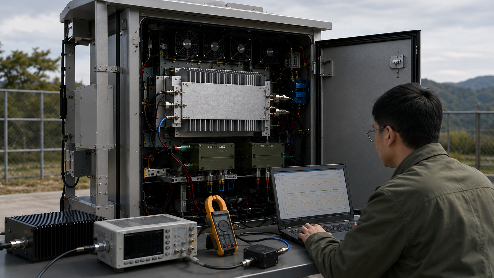
RF power derating is not automatically a device failure, but it can still be a project nonconformance when the hot-state output falls below the agreed requirement.
When selecting RF Power Amplifier Modules for an outdoor C-UAS cabinet, the engineering question is not simply whether output decreases as temperature rises. The real question is whether the delivered unit maintains the required minimum output under the agreed waveform, temperature, operating time, supply, cooling, and RF-load conditions.
A useful derating requirement must define a stabilized normal-temperature reference, a minimum accepted hot-state output, the measurement reference plane, the permitted reduction, and the conditions under which that limit applies. Without these boundaries, neither the supplier nor the customer can distinguish acceptable derating from DC limitation, RF-path loss, protection foldback, or uncontrolled instability.
1. Why Rated Output Is Not Hot-Cabinet Output
A rated RF output normally comes from a defined laboratory condition. It may represent:
- A controlled ambient temperature
- A specific RF waveform
- A stated RF input drive
- A 50 Ω dummy load
- A defined cooling arrangement
- A direct PA-port measurement
- A short or stabilized test period
A deployed C-UAS cabinet may operate under very different conditions:
- Higher internal air temperature
- Direct solar loading
- Restricted airflow
- Long uninterrupted operation
- Several PA channels sharing the same enclosure
- Voltage loss across the 28 V distribution path
- Feeder, connector, and antenna mismatch
- Protection activity after thermal accumulation
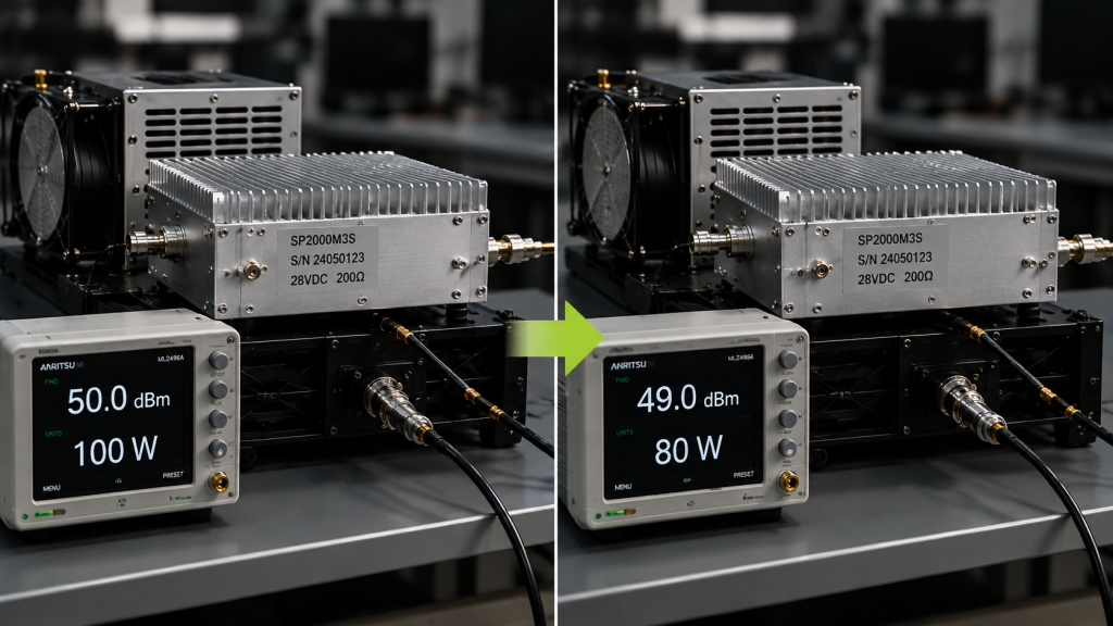
A 100 W bench result therefore does not automatically mean that the system will maintain 100 W after the cabinet reaches its hot-state operating condition.
This does not necessarily make the catalog rating incorrect. It means that the catalog rating and the project acceptance requirement may refer to different conditions.
The buyer should separate at least three output values:
- Stabilized normal-temperature PA-port output
The baseline measured on the same unit after the output and temperature meet the project-defined stabilization condition. - Hot-state PA-port output
The output maintained by the same unit after the PA and cooling system reach the project-defined hot-state condition. - Antenna-port output
The remaining output after feeder, connector, adapter, lightning-protection, and other RF-path losses.
These values cannot be used interchangeably.
The difference between rated power and usable RF output becomes especially important when the project requirement is defined at the antenna rather than directly at the PA port.
For derating approval, the normal-temperature and hot-state measurements should use the same:
- Unit serial number
- Frequency
- Signal waveform
- RF input condition
- Power definition
- Measurement reference plane
- RF load
- Measurement corrections
The normal-temperature reference should not be a cold-start peak, an unstabilized reading, or a catalog value taken from another sample.
Define Stabilization Before Testing
“Stabilized” should not mean that an engineer briefly observes a flat-looking trace.
The test plan should define:
- A minimum observation window
- Permitted output variation during that window
- Permitted temperature trend during that window
- Whether voltage and current must also remain within a stated range
- The minimum required operating duration
Reaching the minimum test duration alone does not prove stabilization. Apparent stabilization also does not replace the required duration.
The stabilized reference and hot-state result must both meet the project-defined observation criteria.
2. How to Define an Acceptable Derated Output
Derating becomes acceptable only when the lower output is defined before testing and still satisfies the system requirement.
A project may use a nominal 100 W module but approve a lower guaranteed hot-state output because the PA must operate inside a high-temperature cabinet with restricted airflow or long-duration loading.
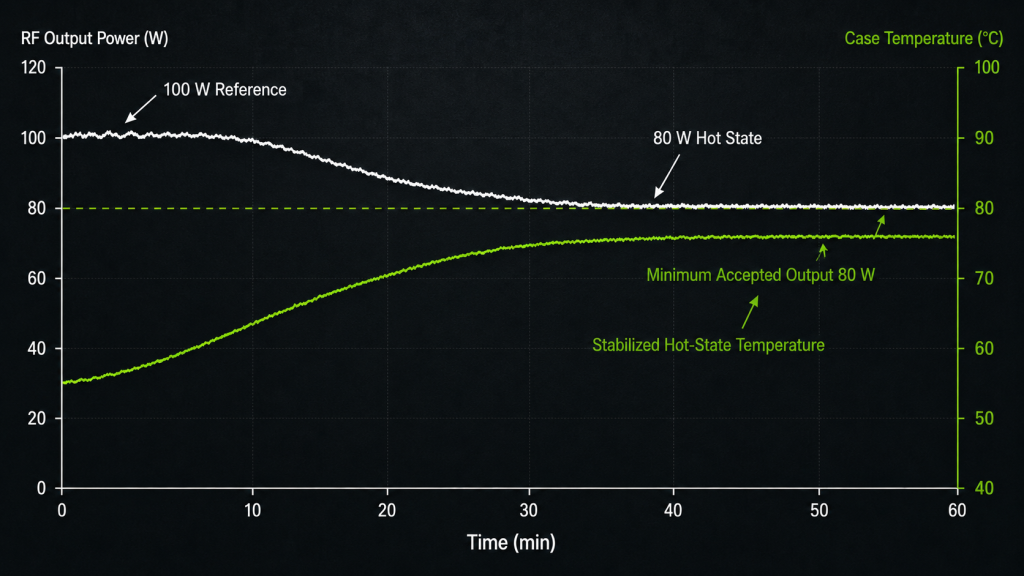
That result may still pass when:
- The stabilized normal-temperature reference is documented
- The minimum hot-state output is agreed in advance
- The output remains above the system requirement
- The same reference plane is used for both measurements
- The 28 V PA-terminal voltage remains within range
- The RF load remains within the approved VSWR boundary
- No prohibited protection event occurs
- The result is repeatable under the same conditions
- The evidence is linked to the delivered unit
Separate Three Types of Hot-State Output Reduction
Not every temperature-related output change has the same engineering meaning.
Temperature-related performance drift occurs when gain, efficiency, or output capability changes as device temperature rises without a defined protection threshold being triggered.
The approval question is:
Does the hot-state output remain above the project minimum?
Controlled protection foldback occurs when the protection system intentionally reduces RF output after a temperature, reflected-power, voltage, or current boundary is reached.
The approval question is:
Is that foldback behavior permitted under the project operating condition?
Specified temperature derating occurs when the supplier defines and guarantees a lower output above a stated temperature or under a stated cooling condition.
The approval question is:
Is the guaranteed derating curve or hot-state output limit supported by repeatable evidence from the delivered unit?
These behaviors should not be grouped together under a vague statement such as “some power reduction is normal.”
Define the Derating Value Clearly
Derating may be expressed in:
- Watts
- Percentage
- dB
The report should state which unit is used and identify the reference value.
For example, if the stabilized reference output is 100 W and the hot-state output is 80 W:
- The absolute reduction is 20 W
- The percentage reduction is 20%
- The report may also state the corresponding dB reduction
However, the primary system acceptance value remains the absolute 80 W hot-state output. A permitted percentage or dB reduction alone does not prove that the system still delivers enough usable power.
The report should not switch between watts, percentage, and dB without showing the corresponding values and the same stabilized reference.
Acceptable RF Power Derating vs Uncontrolled Output Loss
| Acceptance Item | Acceptable Derating | Uncontrolled Output Loss |
|---|---|---|
| Reference condition | Stabilized baseline from the same unit | Catalog value, cold-start peak, or another sample |
| Output limit | Minimum hot-state output defined before testing | No agreed lower output limit |
| Derating value | Reduction stated in W, percentage, or dB | Reduction described only as “normal” |
| Test condition | Temperature, waveform, load, and duration recorded | Only a short or incomplete reading |
| DC condition | PA-terminal voltage remains within range | Voltage falls under RF load |
| RF load | FWD, REV, and VSWR remain within the approved boundary | Load condition is unknown or unstable |
| Protection | Permitted behavior defined in advance | Unexpected alarm, shutdown, or reset |
| Repeatability | Result repeats on the same unit under the same setup | Output changes without a repeatable pattern |
| Traceability | S/N-linked test data | Generic screenshot or sample report |
| Measurement decision | Calibration, correction, uncertainty, and decision rule stated | Pass/fail judgment ignores measurement confidence |
The final decision should compare the measured hot-state output with the project minimum, not only with the percentage difference from the nominal rating.
3. What Causes or Mimics RF Power Derating
A lower hot-state output may come from several different paths. Only some of them are true thermal derating.
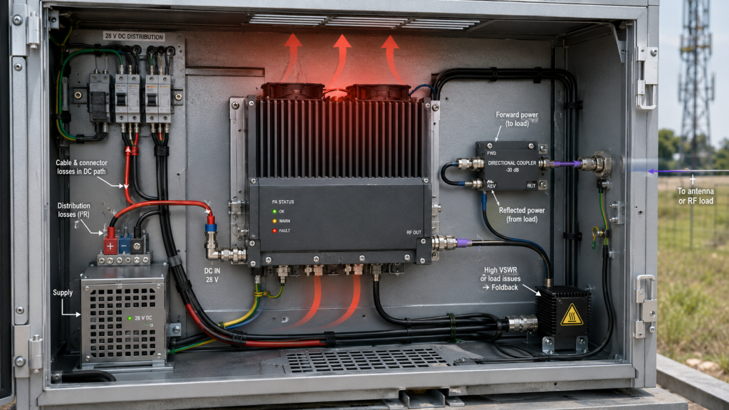
Heat Accumulation
RF conversion is not 100% efficient. Part of the DC input becomes RF output, while the remaining power becomes heat.
During sustained operation, heat must move through:
- The transistor mounting area
- PCB and copper structure
- Thermal interface
- PA housing
- Heatsink or cold plate
- Cabinet airflow
- External environment
If the thermal path cannot remove heat fast enough, device temperature rises. The PA may then show temperature-related drift or controlled thermal foldback.
The relationship between RF output, DC input, efficiency, and enclosure heat should be reviewed through the complete RF PA heat and cabinet cooling boundary.
Cabinet Temperature and Operating Time
Outdoor ambient temperature and internal cabinet temperature are not the same.
Direct sunlight, sealed construction, filter restriction, nearby heat sources, poor airflow, and several active PA channels can raise the cabinet temperature above the reported outdoor value.
The test should distinguish:
- Outdoor ambient temperature
- Cabinet internal air temperature
- PA case or baseplate temperature
- Heatsink inlet or outlet temperature, when relevant
The temperature measurement location and sensor method must be recorded.
Case or baseplate temperature provides a repeatable external test reference. It is not the same as transistor junction temperature unless the supplier has a validated thermal model or a qualified internal sensing method.
A short test may also finish before the module or cabinet reaches the required operating condition. When uninterrupted operation matters, the detailed duration and dwell-test boundary should follow the project’s continuous RF output verification.
DC Limitation Can Mimic Derating
An output reduction is not necessarily caused by temperature.
Voltage may fall across:
- Power cables
- Connectors
- Fuses
- Relays
- Distribution boards
- Shared current paths
The relevant value is the voltage at the PA input while RF output is active.
If the power-supply display remains at 28 V but the PA-terminal voltage falls under load, the cause may be the DC path rather than thermal derating.
Checks for RF PA output drops caused by DC power issues help separate supply limitation from temperature-linked behavior.
RF-Path Loss Is Not PA Derating
Feeder, connector, adapter, and lightning-protection losses reduce antenna-port power without necessarily reducing PA-port output.
If the project compares a bench PA-port result with an installed antenna-port result, the difference cannot automatically be classified as derating.
Both results must use the same reference plane, or the RF-path loss must be measured and documented.
Load-Related Foldback Is a Separate Protection Event
A real antenna path can introduce frequency-dependent mismatch and reflected power.
If reflected power rises and the PA reduces output, the result may be load-related protection foldback rather than thermal derating.
The report should record:
- Forward power
- Reflected power
- VSWR
- Protection threshold
- Output before and after the event
- Recovery behavior
Uncontrolled Instability Requires Investigation
Output change should be treated as uncontrolled when it cannot be explained by the recorded temperature, voltage, current, RF load, input drive, or protection status.
Examples include:
- Irregular output jumps
- Different results under repeated identical tests
- Output loss without a corresponding thermal or electrical change
- Undocumented reset or alarm behavior
- Failure to recover after the approved cooling or reset procedure
These symptoms should not be accepted by labeling them as normal derating.
4. How to Test Derating Without Mixing Heat, DC, and RF-Path Loss
A useful derating test must establish a repeatable baseline and record enough synchronized data to identify the cause of lower output.
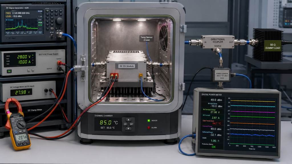
Step 1: Establish a Stabilized Normal-Temperature Baseline
Use the same unit that will undergo the hot-state test.
Connect the PA to a calibrated measurement path and a suitable 50 Ω dummy load.
Record:
- Unit serial number
- Ambient temperature
- Case or baseplate temperature
- Stabilization condition
- Frequency
- RF input level
- Signal waveform
- Average, peak, or peak envelope power definition
- PA-port output
- Forward and reflected power
- VSWR
- PA-terminal voltage
- DC current
- Cooling configuration
- Protection and alarm status
Do not use a cold-start peak as the normal-temperature reference.
Step 2: Establish the Frequency Baseline
Derating may not be equal across the operating band.
A full-power swept RF PA test can identify:
- Lower-output frequencies
- Higher-current frequencies
- Band-edge behavior
- Gain-flatness differences
- Frequencies associated with greater thermal load
The sweep establishes the frequency-domain baseline. It does not replace the hot-state dwell test.
Step 3: Define the Hot-State Condition
Before the test begins, define:
- Minimum uninterrupted run time
- Stabilization observation window
- Signal waveform
- Duty cycle
- Dwell frequency or switching sequence
- Ambient and cabinet temperature
- Cooling method
- Temperature measurement point
- PA-terminal voltage range
- RF load and VSWR boundary
- Minimum accepted output
- Permitted protection behavior
- Measurement decision rule
If several frequencies require verification, state whether each receives a separate dwell test or whether the test follows the real operating sequence.
Step 4: Control the RF Input Condition
The test plan should state whether RF input drive remains fixed or may be adjusted.
Record:
- Initial RF input level
- Input-drive trend during the test
- Whether automatic level control is enabled
- Any manual or automatic drive adjustment
- Gain or required-drive change at hot state
Constant output achieved only by increasing RF input drive should not be reported as unchanged PA behavior.
When automatic level control maintains the output, the report should still show whether the PA required more drive, entered deeper compression, or consumed additional system margin.
The acceptance plan should state whether it evaluates:
- Output power only
- Output and gain
- Output and required input drive
- The complete controlled RF chain
Step 5: Record Synchronized Trends
Record the following values against the same time axis:
- RF output
- RF input drive
- PA-terminal voltage
- DC current
- Case or baseplate temperature
- Forward power
- Reflected power or VSWR
- Protection and alarm status
The trend relationships help identify the cause:
- Output falls while temperature rises, with stable voltage, input drive, and load: temperature-related derating is more likely.
- Output remains constant only because input drive rises: PA gain or required drive has changed.
- Output falls while PA-terminal voltage falls: investigate the DC path.
- Output falls while reflected power rises: investigate the RF load or antenna path.
- Output falls at a documented protection threshold: controlled foldback may be operating.
- Output changes without a corresponding condition: investigate uncontrolled instability.
Step 6: Confirm Repeatability and Measurement Confidence
When the result is near the acceptance limit, repeat the test on the same unit using the same:
- Signal
- Frequency
- Input-drive condition
- Reference plane
- Cooling condition
- Voltage boundary
- RF load
- Measurement setup
For production quantities, the RFQ should separately define whether verification applies to every unit or to an agreed sampling plan.
Design-validation data may establish the test method, but it does not automatically replace the unit-level or sampling evidence required for shipment acceptance.
The report should also identify:
- Measurement equipment
- Calibration status
- Cable and connector correction
- Coupler, attenuator, and sensor correction
- Total path correction
- Measurement uncertainty near the pass/fail boundary
When the result is close to the minimum accepted output, the RFQ or test plan must define the decision rule in advance.
The agreed rule may include:
- A guard band
- A conservative pass limit
- A stated treatment of measurement uncertainty
There is no single decision rule for every project. The important point is that the supplier and customer agree on the rule before reviewing the result.
A reading slightly above the nominal limit does not automatically prove compliance when the uncertainty range or agreed guard band extends below the acceptance boundary.
5. How to Reduce Derating Before Oversizing the PA
When hot-state output falls below the approved limit, the first response should not automatically be a higher-power PA.
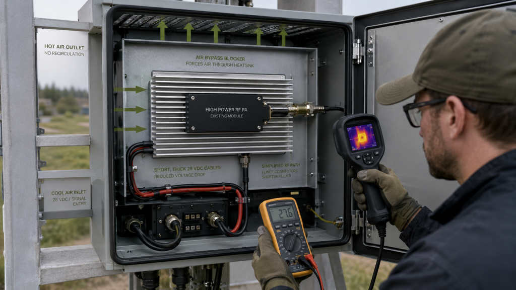
Improve the Thermal Path
Check whether heat can move from the PA into the cabinet cooling system without excessive thermal resistance, restricted airflow, or hot-air recirculation.
Priority items include:
- Thermal-interface contact
- Mounting flatness
- Heatsink capacity
- Airflow through the heatsink
- Cabinet inlet and outlet arrangement
- Filter restriction
- Hot-air recirculation
A larger heatsink will not solve the problem if airflow bypasses the fins or remains trapped inside the enclosure.
Restore PA-Terminal Voltage and Reduce RF-Path Loss
Verify the 28 V path under full RF load and correct avoidable loss across cables, connectors, fuses, relays, and distribution boards.
When the requirement is defined at the antenna, also review feeder length, cable type, connector count, lightning-protection loss, and antenna match.
Reducing DC or RF-path loss may recover required system output without increasing cabinet heat.
Add Output Margin Only After the Other Paths Are Verified
A higher-power PA can provide margin when it operates below its maximum capability.
However, a larger module may also increase:
- DC current
- Heat generation
- Power-distribution requirements
- Heatsink size
- Cabinet airflow demand
The final choice should be based on measured hot-state output and the complete thermal and electrical boundary, not only on a larger catalog rating.
6. What Evidence and RFQ Limits Should Approve the Cabinet
A derating approval package should identify the tested unit, stabilized baseline, hot-state result, operating boundary, measurement confidence, and final decision.
Minimum Report Content
The report should include:
- Product model and serial number
- Stabilized normal-temperature reference
- Hot-state output
- Derating value in W, percentage, or dB
- Minimum accepted absolute output
- Frequency, waveform, and input-drive condition
- Output reference plane
- Test duration and stabilization criteria
- Environmental and cooling conditions
- Temperature measurement location
- PA-terminal voltage and current
- FWD, REV, and VSWR
- Protection behavior
- Calibration status and total path correction
- Measurement uncertainty and decision rule
- Final pass or fail result
RFQ Limits to Define Before Testing
The RFQ should define:
- Frequency range and signal waveform
- Stabilized reference condition
- Minimum accepted hot-state output
- Permitted derating unit and reference value
- Output reference plane
- Fixed or controlled RF input condition
- Minimum run time and stabilization rule
- Cabinet temperature and cooling method
- Approved 28 V terminal-voltage range
- RF load and VSWR boundary
- Permitted protection behavior
- Unit-level or sampling requirement
- Measurement uncertainty and guard-band rule
- S/N-linked report format
A supplier should not be asked only:
Can the PA operate at 50°C?
The RFQ should ask:
What minimum output will the delivered unit maintain at the defined reference plane, waveform, input-drive condition, temperature, voltage, RF load, and operating duration?
That question creates a result that can be measured and approved.
FAQ
Is RF Power Derating Always a Product Failure?
No.
RF power derating is not automatically a device failure, but it may still be a project nonconformance if the hot-state output falls below the agreed minimum.
Controlled protection foldback or a specified derating curve may be acceptable only when the behavior is defined in advance and supported by unit-specific evidence.
How Should Derated RF Output Be Measured?
The stabilized normal-temperature and hot-state outputs should be measured on the same unit at the same reference plane using compatible frequency, waveform, RF input condition, RF load, and measurement corrections.
The report should also record PA-terminal voltage, current, temperature, input-drive trend, FWD, REV, VSWR, and protection status.
Can a Single Hot-State Power Screenshot Prove Acceptable Derating?
No.
A single screenshot does not establish the stabilized baseline, test duration, temperature boundary, input-drive condition, terminal voltage, RF load, protection status, repeatability, calibration, uncertainty, or decision rule.
Acceptable derating requires synchronized and S/N-linked evidence showing that the hot-state output remains above the agreed limit under the defined conditions.
Conclusion
RF power derating should not be used as a general label for every hot-cabinet output reduction. Temperature-related drift, specified derating, protection foldback, DC limitation, RF-path loss, and uncontrolled instability require different evidence.
Approval should be based on a stabilized reference from the same unit, a defined minimum hot-state output, a consistent measurement reference plane, and synchronized thermal, electrical, RF-load, input-drive, and protection data.
RF SKYPOWER can support early engineering review for hot-cabinet RF power derating requirements. Send the frequency, waveform, stabilized reference output, minimum hot-state output, reference plane, input-drive condition, run time, cabinet and cooling conditions, 28 V terminal-voltage range, RF-load boundary, protection requirements, and S/N-linked report format.