


Output Power in C-UAS systems should not be judged by rated watts alone, because datasheet wattage is usually measured under defined module-level test conditions. Real usable watts depend on the complete RF chain, including feeder loss, connector path, antenna load, thermal state, supply margin, duty cycle, protection behavior, and the power measurement reference point.
For system integrators and RF engineers, the practical choice is not only whether to buy a 50W, 100W, or 200W PA module. The harder question is whether that output power can remain stable, transferable, controllable, and repeatable after the module is installed in a fixed-site C-UAS system. Rated watts describe what the PA can produce under controlled conditions; usable watts describe what the system can actually deliver and sustain.
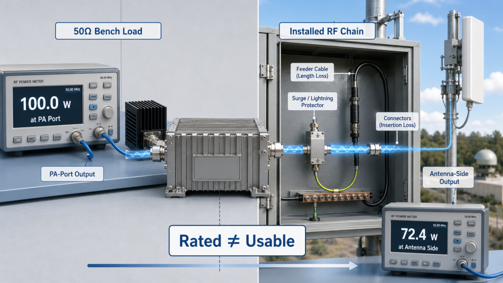
The central conflict is simple: rated output is a module number, but usable output is a system result. A module may reach 100W on a 50Ω bench load, yet deliver less useful power after feeder cable loss, connector transitions, antenna mismatch, hot cabinet operation, voltage drop, or protection derating. The engineering goal is not to reject wattage ratings. The goal is to judge how many watts remain usable before approving the C-UAS RF chain.
1. Why Can Rated Output Power Mislead C-UAS Engineers?
RF Power Amplifier Output Power can mislead C-UAS engineers when a rated watt number is treated as usable system power without checking the test conditions behind it. A “100W PA” label usually means the module reached that output under a specific frequency point, input drive, supply voltage, load, temperature, cooling condition, and test duration.
Here’s the engineering point: a watt number without test conditions is not an engineering answer. If the datasheet does not define where and how power was measured, you cannot know whether the result applies to your installed RF chain.
What Does Rated Output Usually Prove?
Rated output proves baseline module capability. It tells you the PA can reach a defined output level under controlled conditions, but it does not prove antenna-port output or hot-state sustained output.
Typical rated-output conditions may include:
- Specified frequency point or limited frequency set
- Stable 28V DC supply at the module terminal
- Defined input drive level
- 50Ω dummy load
- Controlled ambient temperature
- Defined heatsink or cooling method
- Short test duration or stated duty cycle
- Calibrated test cable and instrument loss
Where Does the Misunderstanding Start?
The misunderstanding starts when buyers assume module output equals system output. In a real C-UAS cabinet, the RF signal must travel through cables, connectors, filters, antenna feeds, and a real antenna load before it becomes useful to the system.
Key Takeaway: Rated output is a starting value, not a field guarantee. It must be translated into usable system output before procurement approval.
| Wrong Assumption | Better Engineering Check |
|---|---|
| 100W label means 100W in the system | Ask where the 100W was measured |
| Bench output equals antenna output | Check feeder and connector loss |
| One frequency proves the full band | Request multi-point or sweep data |
| Cold short test proves field use | Review hot-state and duty-cycle output |
| 50Ω load proves antenna behavior | Check VSWR and reflected power status |
This table helps engineers separate a useful module rating from a risky system assumption.
2. When Is Rated Output Still a Useful Starting Point?
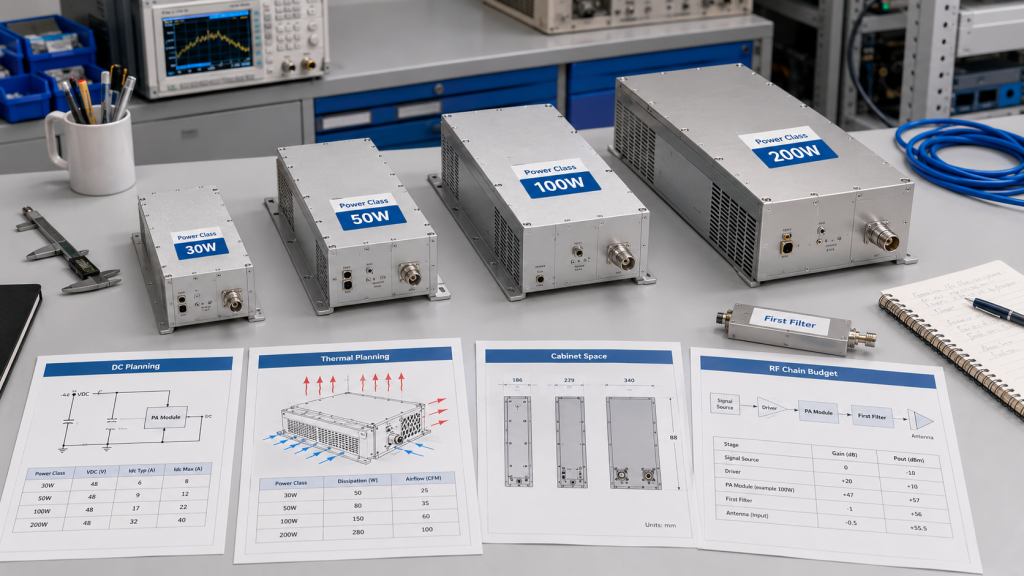
RF Power Amplifier Output Power is a useful starting point when the rated value is supported by clear test conditions and used only as the first screening layer. It helps engineers compare module classes, estimate DC demand, plan cooling, size cabinets, and shortlist suitable power levels.
The practical risk is clear: rejecting rated output completely is just as wrong as trusting it blindly. You need the number, but you need the conditions behind the number more.
What Can Rated Output Help You Decide?
Rated output helps you decide whether the module belongs in the right power family. A 30W, 50W, 100W, and 200W module will create different expectations for heat, current, size, cost, antenna path, and protection design.
Rated output can support early decisions such as:
- Initial module class selection
- DC supply sizing estimate
- Thermal structure planning
- Cabinet space planning
- RF chain budget draft
- Cost comparison between power levels
- Early review of RF Power Amplifier modules
When Is It Closer to Real Output?
Rated output is closer to real output when the project uses a short RF path, controlled load, stable power supply, known cooling, and limited operating duration. In that case, the system is closer to the factory test environment.
Key Takeaway: Rated output is not the final answer, but it is a necessary first filter when the test reference is clear.
| Rated Output Use | What It Can Support | What It Cannot Prove Alone |
|---|---|---|
| Power level screening | 50W vs 100W vs 200W comparison | Installed antenna-path output |
| DC planning | Current and supply estimate | Real voltage at module terminal |
| Thermal planning | Initial heat-load estimate | Hot-state sustained output |
| RFQ discussion | Supplier comparison | Field acceptance performance |
| Lab testing | Controlled module behavior | Full fixed-site C-UAS behavior |
This table keeps rated output in the right role: useful, but incomplete.
3. What Makes Output Power Usable in C-UAS?
RF Power Amplifier Output Power becomes a real selection requirement when the project must deliver stable usable RF output through an installed C-UAS system, not just pass a module bench test. Fixed-site systems, long antenna paths, wideband coverage, and long-duty operation all make usable output more important than the label wattage.
This is where system integrators should pay attention: if the customer will judge the system by field performance, the output must be reviewed as a system result. In low-altitude security and C-UAS EW solutions, the RF chain includes module behavior, feeder routing, antenna location, power delivery, cooling, and controller decisions.
What Project Conditions Trigger This Review?
You should prioritize usable output when the deployment has real system stress. These conditions increase the gap between rated output and field output.
Common triggers include:
- Fixed-site low-altitude security
- Airport perimeter systems
- Critical infrastructure protection
- Long feeder cable paths
- Remote antenna installation
- Multi-module RF cabinets
- Wideband output requirements
- High duty cycle
- Hot outdoor cabinet conditions
- Acceptance based on antenna-side or system-level result
What Does Usable Output Actually Mean?
Usable output does not mean antenna-port power only. It means power that remains stable, transferable, controllable, repeatable, and visible to the system under the defined operating condition.
Key Takeaway: Usable output becomes the real requirement when the customer buys a working C-UAS system, not a standalone PA number.
| Deployment Condition | Rated Output Risk | Usable Output Check |
|---|---|---|
| Long feeder path | Antenna power may be lower | Cable and connector loss review |
| Outdoor cabinet | Heat may reduce sustained output | Hot-state test |
| Wideband operation | Edge points may be weak | Full-band output data |
| Multi-module cabinet | Shared power and heat stack up | Simultaneous-load test |
| Real antenna load | Reflected power may rise | VSWR and protection review |
This table shows when the project should move from datasheet review to system-output validation.
4. What Reduces Output Power After the PA Port?
RF Power Amplifier Output Power is reduced by feeder loss and connector loss when power measured at the PA port must travel through a real RF path before reaching the antenna. The PA may be working correctly, while the antenna receives less power because the installed path absorbs part of the signal.
Here’s the field reality: module-port power and antenna-port power are different measurement points. If the RFQ does not define the output reference point, two teams can both be “right” and still disagree during acceptance.
What Parts of the RF Path Consume Power?
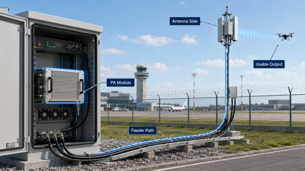
C-UAS fixed-site systems often place antennas away from the PA cabinet. This makes the RF path part of the output-power decision, not an installation detail.
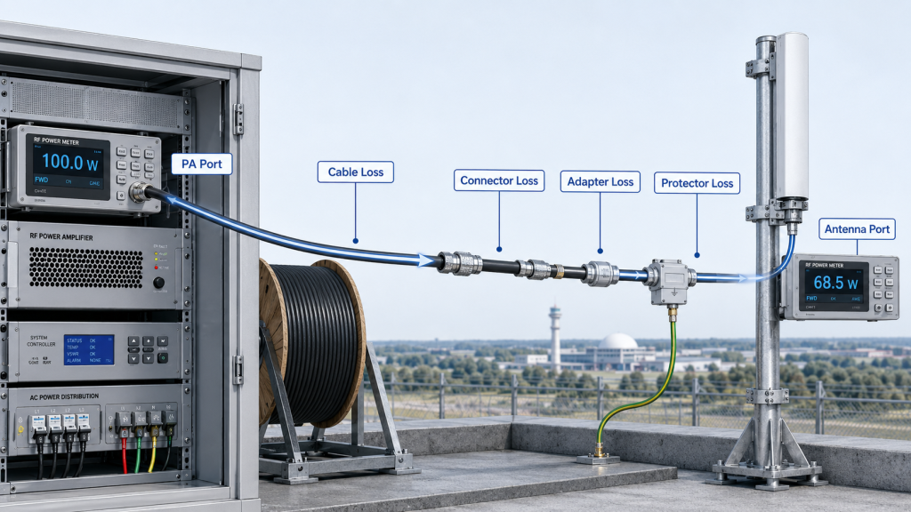
Loss can come from:
- Coaxial feeder cable
- Connector pairs
- Temporary adapters
- Waterproof RF joints
- Lightning protection devices
- Filters, combiners, or switching networks
- Cable bends and routing stress
- Poor connector contact after installation
For deeper review, engineers can compare PA-port and antenna-end readings using a method similar to RF Power Amplifier feeder cable loss testing.
Why Does Frequency Make This Worse?
Higher frequencies usually make cable and connector quality more visible. A path that looks acceptable at a lower band may create a larger loss at higher C-UAS operating frequencies.
Key Takeaway: Usable output must define the measurement point. PA-port rated output is not the same as delivered output after the feeder path.
| RF Path Element | How It Reduces Usable Output | Better Check |
|---|---|---|
| Long feeder cable | Insertion loss before antenna | Measure or calculate path loss |
| Connector chain | Small losses add together | Count every transition |
| Adapter use | Adds loss and mismatch risk | Avoid unnecessary adapters |
| Waterproof joint | Contact and sealing affect RF path | Inspect and retest after assembly |
| Lightning protection | Adds insertion loss | Include it in path budget |
This table helps engineers find hidden losses before blaming the PA module.
5. What Do Fixed-Site C-UAS Acceptances Reveal About Output?
RF Power Amplifier Output Power in fixed-site C-UAS acceptance often reveals the gap between rated PA output and usable system output. The issue may not appear during the first bench test; it often appears when the installed antenna path, cabinet heat, supply wiring, and protection feedback are tested together.
The problem is no longer whether the PA is “100W.” The real acceptance question is whether the complete RF chain can repeat usable output under the agreed site condition.

What Happens in Airport Perimeter Systems?
In an airport perimeter deployment, the PA cabinet may sit in a service room or equipment shelter while antennas are mounted on towers, rooftops, or fence-line points. Long feeder paths, weatherproof connectors, lightning protection, and outdoor routing can reduce delivered power even when PA-port output remains correct.
In an airport counter-UAS RF deployment, the practical checks should include:
- PA-port output
- Feeder path length
- Antenna-port output estimate
- Outdoor connector quality
- Hot-state output under long operation
- Protection status during antenna load testing
- Repeatability after cabinet closure
What Happens in Critical Infrastructure Sites?
Critical infrastructure sites usually care more about stable operation than a clean one-time number. A module that passes short output testing may still become risky if the cabinet runs hot, the duty cycle is high, or the supply margin becomes weak during multi-module operation.
For critical infrastructure Counter-UAS deployment, acceptance should compare rated output against sustained, repeatable, field-condition output.
Key Takeaway: Fixed-site acceptance proves why usable output is a system result. The site layout decides how much of the rated PA power remains useful.
| Fixed-Site Scenario | What Rated Output Misses | What Engineers Should Review |
|---|---|---|
| Airport perimeter | Long RF path loss | Antenna-side power budget |
| Critical infrastructure | Long-duty operation | Hot-state sustained output |
| Border station | Remote maintenance difficulty | Repeatable test evidence |
| Multi-band cabinet | Uneven band behavior | Full-band and channel review |
| Multi-module cabinet | Heat and current stacking | Simultaneous-load condition |
This table connects deployment type to the output-power question that must be answered before acceptance.
6. How to Check Output Power Under Heat and Duty Cycle?
RF Power Amplifier Output Power changes under heat, duty cycle, and supply stress because a PA that reaches rated power briefly may not sustain the same output during hot, high-current, long-duty C-UAS operation. Cold-state output is not always the same as hot-state usable output.
The better check is simple: test the module under the operating condition that looks most like your project. If your fixed site expects long operation in a warm cabinet, short room-temperature output is not enough.
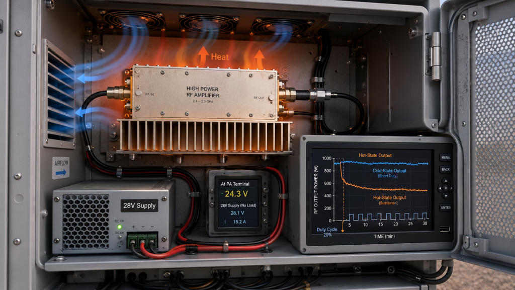
Why Does Thermal State Matter?
High-power PA modules convert DC energy into RF output and heat. If the thermal path is weak, heat can build up until output drops, protection logic responds, or the system becomes unstable.
Review these thermal conditions:
- Ambient temperature
- Heatsink size and contact
- Cabinet airflow
- Module spacing
- Full-load operating time
- Temperature feedback or alarm threshold
- Output after heat soak
Poor airflow can turn a correct module-level result into a weaker cabinet-level result, which is why RF Power Amplifier thermal margin should be reviewed before long-duty operation.
Why Does Supply Margin Matter?
A 28V supply label does not prove 28V at the module terminal under full current. Long DC cables, weak terminals, poor crimping, shared rails, and current limits can reduce module-side voltage.
The issue may look like an RF problem, but the source is the DC path. A related review is covered in how to power RF Power Amplifiers without output drops.
Key Takeaway: Usable output should be checked after the PA is hot, loaded, powered through the real DC path, and running at the expected duty cycle.
| Stress Factor | What Can Change | Output-Power Risk |
|---|---|---|
| Heat buildup | Device efficiency and protection state | Sustained output falls |
| High duty cycle | Average thermal load | Rated peak cannot continue |
| Voltage drop | Module terminal voltage | RF conversion weakens |
| Current limit | Supply cannot support load | Output becomes unstable |
| Shared DC rail | Modules pull each other down | Multi-channel output varies |
This table helps engineers avoid approving a power level that only works under short clean tests.
7. How to Verify Output Power Across C-UAS Bands?
RF Power Amplifier Output Power must be checked across the band because one strong frequency point does not prove usable output across all C-UAS target frequencies. Wideband PA behavior can vary at the low edge, center, high edge, and project-critical points.
Here’s the useful part: wideband coverage is not only a frequency-range label. It must be supported by output power, gain behavior, current draw, heat condition, load response, and repeatability across the band.
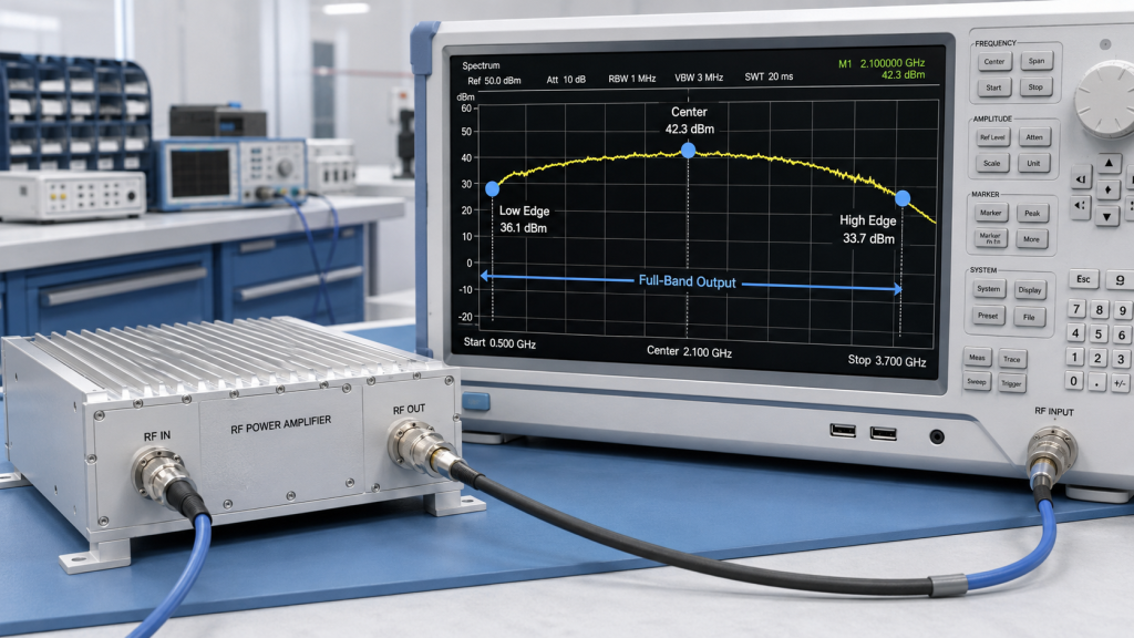
What Can a Single Frequency Hide?
A single center-frequency result may hide weak band-edge behavior. For example, a module may look strong near the easier part of the band while showing lower output, higher current, more heat, or greater VSWR sensitivity near the edges.
Ask for evidence at:
- Low band edge
- Center point
- High band edge
- Project-critical frequencies
- Hot-state points
- Worst-case load condition
- Output trend, not only one peak value
How Should Engineers Read Full-Band Data?
Engineers should compare output consistency, not only maximum output. A frequency point with acceptable wattage but abnormal current, rising temperature, or unstable reflected-power status should not be treated as clean usable output.
For wideband modules, verified wideband RF Power Amplifier performance is needed because one rated output point cannot prove usable output across the full operating band.
Key Takeaway: For wideband C-UAS modules, usable output must be judged across the operating band, not from the best-looking frequency point.
| Data Type | Weak Evidence | Better Evidence |
|---|---|---|
| Output power | One center point | Multi-point or sweep data |
| Gain | Single gain value | Gain trend across band |
| Band-edge output | Wattage only | Wattage, current, temperature, and alarm state |
| Heat | Cold data only | Hot-state output trend |
| Load behavior | Dummy load only | Load and VSWR response review |
This table helps buyers avoid approving a wideband module based on one attractive number.
8. How Do Load, VSWR, and Protection Affect Output?
RF Power Amplifier Output Power is affected by load, VSWR, and protection logic because antenna mismatch can increase reflected power and force the PA or controller to reduce, alarm, or shut down output. A 50Ω dummy-load result does not automatically prove stable behavior with a real antenna path.
This is where protection should be understood correctly: protection is not a weakness. It is necessary for safe operation, but it changes what output remains usable when the RF chain is stressed.
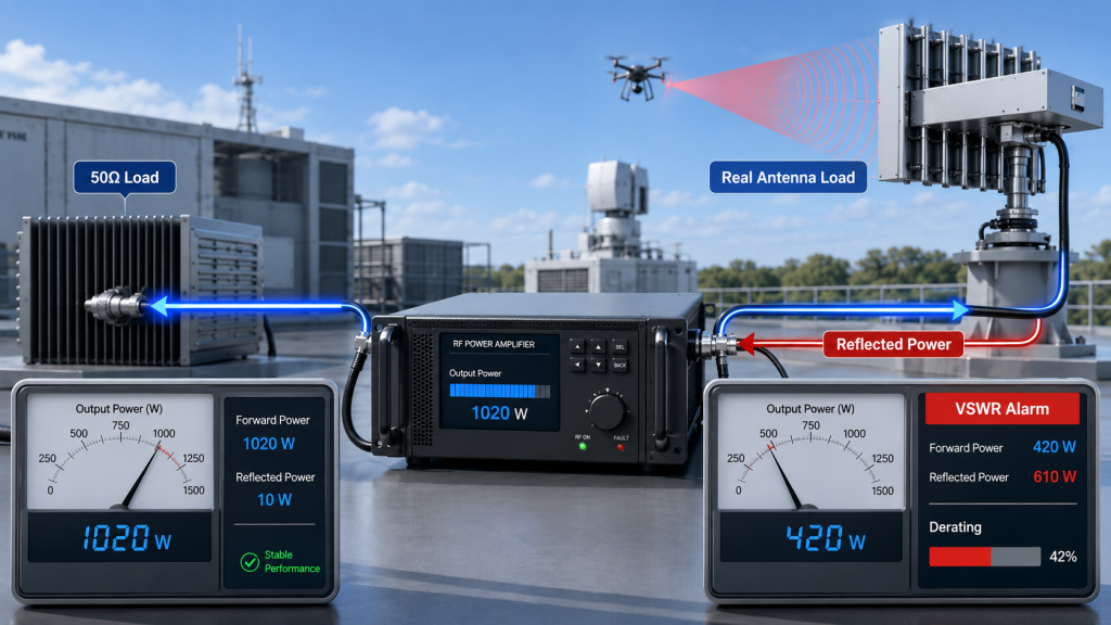
Why Is a 50Ω Load Not the Whole Story?
A dummy load helps isolate module behavior. It is useful for factory testing and troubleshooting. The problem starts when teams assume it represents every installed antenna condition.
A real antenna path can introduce:
- Frequency-dependent mismatch
- Reflected power
- Connector-related impedance changes
- Water ingress or outdoor joint problems
- Cable damage or bending
- Load variation across band
- Intermittent fault behavior
A real RF Power Amplifier antenna load can change reflected power and protection behavior, reducing usable output even when rated output is correct on a 50Ω bench load.
Why Is Confirmed Output Different from Commanded Output?
For C-UAS controllers, commanded output and confirmed output must be separated. A control command can request RF power, but usable output should be confirmed through forward power, reflected power, temperature, voltage, current, and alarm feedback.
Without status feedback, the controller may believe the channel is active while protection logic has already reduced or interrupted output. This is why RF Power Amplifier control logic should be reviewed before system testing, not after a protection event appears in the field.
Key Takeaway: Load testing and protection visibility turn output power from a blind command into a managed system condition.
| Load or Control Condition | Possible PA Response | System-Level Meaning |
|---|---|---|
| Good 50Ω load | Stable rated output | Module baseline is proven |
| Mild mismatch | Reflected power rises | Watch VSWR trend |
| Severe mismatch | Alarm or derating | Usable output decreases |
| ON command only | Output is requested | Output is not yet confirmed |
| Forward and reflected feedback | Output is visible | Controller can judge real state |
This table helps engineers treat protection status as part of usable output, not as a separate issue.
9. What Output Power Data Should Engineers Request?
RF Power Amplifier Output Power should be requested with test reference point, frequency data, supply condition, thermal state, duty cycle, load type, feeder assumptions, protection status, and repeatable report format before RFQ. Asking only “How many watts?” is not enough for a serious C-UAS project.
The practical risk is clear: two suppliers can both quote “100W,” but one may mean PA-port cold output at one frequency while another can provide full-band, hot-state, S/N-bound evidence.
What Should Be Included in the RFQ?
A useful RFQ should define how the output number will be judged. It should reduce interpretation gaps between procurement, RF engineering, system integration, and the supplier.
Request these items:
- Rated output reference point
- PA-port or antenna-port definition
- Frequency points or full-band sweep
- Input drive level
- Supply voltage at module terminal
- Full-load current
- Ambient temperature
- Cooling condition
- Test duration
- Duty cycle
- Load type
- Feeder loss assumption
- VSWR or reflected power status
- Protection state during test
- S/N-bound test report
What If the Supplier Only Gives a Wattage Label?
If a supplier can only provide a wattage label but cannot define the test point, load, voltage, temperature, frequency condition, or protection status, the quotation should be treated as incomplete for fixed-site C-UAS integration.
A useful RF Power Amplifier test report does not only list watts. It ties output power to frequency, voltage, current, temperature, load, protection status, and serial number, so retesting remains possible if field results disagree later.
Key Takeaway: A good RFQ turns output power from a sales number into a repeatable engineering requirement.
| RFQ Item | Why It Matters | Evidence to Request |
|---|---|---|
| Output reference point | Avoids PA-port vs antenna-port confusion | Test setup diagram |
| Frequency data | Finds weak band points | Sweep or multi-point table |
| Supply voltage | Confirms module-side condition | Voltage under full load |
| Thermal state | Shows sustained behavior | Hot-state output data |
| Protection status | Explains derating or alarms | Alarm and VSWR record |
| Serial number | Supports traceability | One Report One Unit record |
This table can be used directly by engineering and procurement teams before quotation.
10. How to Judge Usable Output Power in C-UAS?
RF Power Amplifier Output Power is truly usable only when the rated PA output can survive feeder loss, antenna load, thermal stress, supply limits, duty cycle, protection behavior, and repeatable C-UAS system testing. The final decision should come from a chain review, not a wattage label.
Here’s the engineering point: the best approval process starts from the field requirement and works backward to the module. Do not start with “200W is stronger than 100W.” Start with “Where must usable output be delivered, under what conditions, and for how long?”
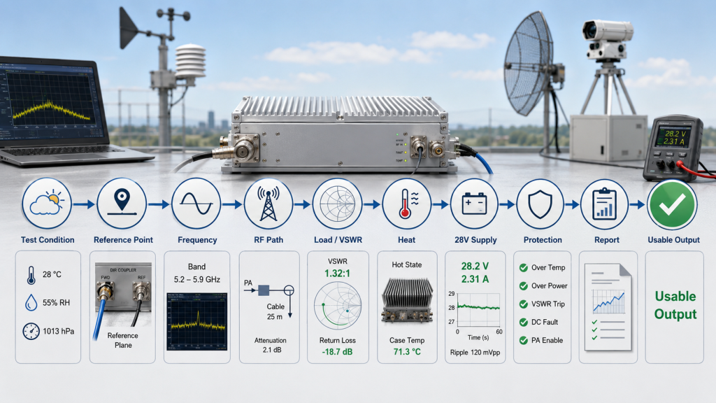
What Decision Sequence Should Engineers Use?
Use a step-by-step review before approval. The goal is not to make the process complicated; the goal is to avoid approving a number that does not survive installation.
A practical sequence is:
- Confirm the rated-output test conditions.
- Define the output reference point.
- Check target frequencies and band edges.
- Estimate feeder and connector loss.
- Review antenna load and VSWR behavior.
- Compare cold-state and hot-state output.
- Confirm module-side supply voltage.
- Match duty cycle to thermal design.
- Review protection and controller feedback.
- Require repeatable test evidence.
Where Should Source-Factory Support Enter?
As a source factory for RF Power Amplifier modules and C-UAS core components, RF SKYPOWER can support early engineering review by checking frequency range, rated output, usable output, feeder path, antenna load, thermal margin, supply margin, duty cycle, protection logic, and repeatable test evidence before final module approval.
When selecting high-power RF Power Amplifier modules, the safer path is to review usable output before final module approval, not after the cabinet and antenna path are already fixed.
Key Takeaway: Usable output is not one parameter. It is the final result of RF, thermal, DC, load, control, and reporting conditions working together.
| Decision Area | Question to Ask | Approval Signal |
|---|---|---|
| Test condition | How was rated power measured? | Clear setup and conditions |
| Reference point | PA port or antenna port? | Defined measurement location |
| Frequency | Is output stable across the band? | Full-band evidence |
| RF path | What loss exists after the PA? | Cable and connector budget |
| Load | What happens with antenna mismatch? | VSWR response is known |
| Heat and duty | Can output continue hot? | Hot-state data |
| Supply | Is voltage stable at the module? | Full-load voltage record |
| Report | Can results be repeated later? | S/N-bound evidence |
This table gives engineers a final approval map before turning a quoted wattage into a system commitment.
FAQ
Can I use rated output power to choose a C-UAS PA module?
Yes, but only as the first screening value. You still need to verify the test conditions, output reference point, frequency behavior, feeder loss, thermal state, duty cycle, supply margin, and load response before treating it as usable system output.
How do I know if 100W at the PA port is enough?
You know only after defining where the system needs usable output. If the requirement is at the antenna port, you must subtract feeder and connector losses and then check whether the remaining output is stable under real load and heat.
What should I check before comparing 100W and 200W modules?
Check the frequency band, full-band output trend, cable path, antenna load, thermal margin, supply current, duty cycle, protection behavior, and report quality. A larger wattage label does not automatically produce a better C-UAS system.
When should I ask for hot-state output data?
Ask for hot-state output data when the system will run long duty cycles, work in outdoor cabinets, operate in high ambient temperature, or use multiple PA modules in the same enclosure. Cold short-test data is not enough for those conditions.
What’s the best proof of usable RF output?
The best proof is repeatable test evidence that states frequency, output reference point, supply voltage, current, thermal condition, load, VSWR or reflected power status, duty cycle, and serial number. A single watt number is weak evidence.
Conclusion
Rated RF output power is only the starting point for C-UAS RF Power Amplifier selection. It shows what the PA module can produce under defined test conditions, but it does not automatically prove usable output in a fixed-site C-UAS system. Feeder loss, antenna distance, connector path, thermal state, supply margin, duty cycle, wideband behavior, load mismatch, VSWR protection, and controller feedback can all change how much RF power remains useful.
For engineers and technical buyers, the practical lesson is simple: do not select a C-UAS PA module by watt rating alone. Ask where the power is measured, across which frequencies, under what voltage and temperature, through which load, at what duty cycle, and with what protection state. The real question is not only “How many watts is the module rated for?” but “How much output remains usable in the complete C-UAS RF chain?”
RF SKYPOWER supports fixed-site low-altitude security projects by helping integrators review rated output, usable output, feeder path, antenna load, thermal margin, supply margin, protection logic, and repeatable test reports before system integration. If your team needs to review module power, antenna-path loss, hot-state output, or RFQ test evidence before final selection, you can contact us today.
Field-ready C-UAS performance starts with verified usable RF output, not catalog wattage shortcuts.