


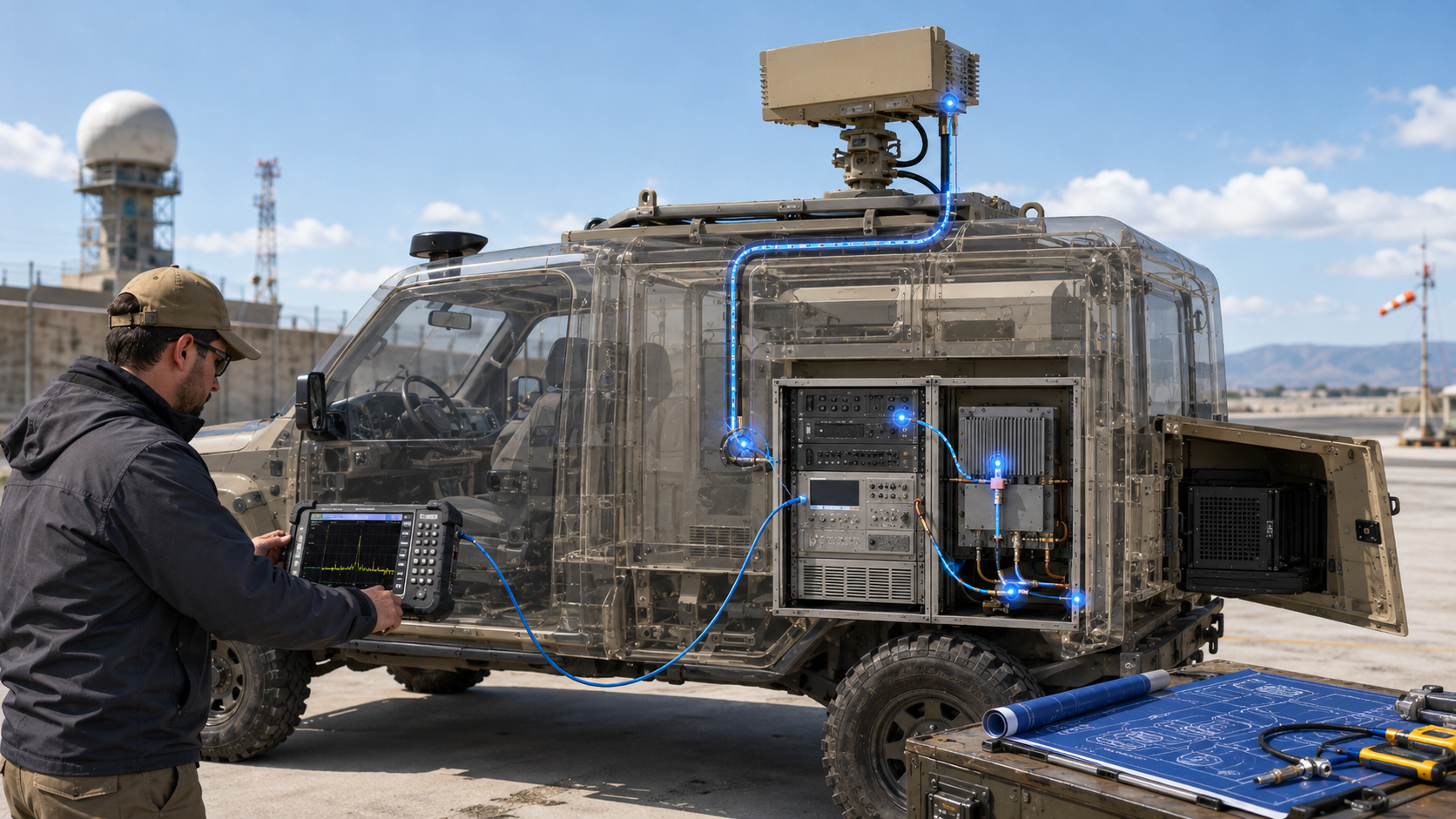
RF power measurement failures in vehicle C-UAS usually happen when teams compare watts measured at different system boundaries as if they were the same result. A “100W” reading at the PA module port, cabinet RF output, feeder end, antenna input, or field boundary can all be correct, but each value describes a different part of the installed RF chain.
The central conflict is simple: module-port output proves PA-side capability, while vehicle C-UAS RF power measurement must prove which system boundary is being tested, accepted, and repeated later.
For system integrators and RF engineers, the practical question is not only whether the PA module can reach its rated output. The harder question is whether the same measurement point, vehicle state, load condition, and report evidence are used during supplier testing, cabinet integration, field acceptance, and later troubleshooting. If these reference points are mixed, the system may fail acceptance even when the module, cable path, and antenna are not actually faulty.
1. How to Identify RF Power Test Point Errors in Vehicle C-UAS
RF power test points get mixed in vehicle C-UAS because Vehicle C-UAS RF power data often comes from several physical boundaries, while teams describe all of them as “output power.” The PA supplier may mean the module output connector, the cabinet builder may mean the external RF bulkhead, and the field team may mean the antenna input after installation.
Here’s the engineering point: these are not the same result. A wattage number without a named measurement plane can make a healthy module look weak, a lossy vehicle path look acceptable, or a field complaint look impossible to reproduce.
Which Teams Use Different Meanings?
Different teams use different meanings because each team owns a different part of the RF chain. The RF engineer checks PA behavior, the vehicle integrator sees cabinet routing, the antenna team sees feed-point delivery, and the customer judges mission effect.
Before comparing output data, ask:
- Was the reading taken at the PA module port?
- Was it taken at the cabinet RF output?
- Was it taken after the installed feeder path?
- Was it taken at the antenna input?
- Was it inferred from field effect or coverage?
- Were vehicle operating conditions recorded?
What Is the First Acceptance Risk?
The first acceptance risk is comparing correct numbers from different boundaries. If one report shows module-port power and another test shows antenna-feed power, both may be technically valid but still unsuitable for direct comparison.
Key Takeaway: The first step in RF power judgment is not choosing a wattage; it is naming the measurement point.
| Mixed Statement | Better Question | Why It Matters |
|---|---|---|
| “The system is 100W” | 100W measured where? | Prevents false comparison |
| “The antenna power is low” | Compared with which point? | Separates PA and path issues |
| “Factory data passed” | Was the field point identical? | Makes retest fair |
| “Coverage is weak” | Was RF power checked first? | Avoids blaming radiation on watts only |
| “The module is unstable” | Did the reference plane change? | Prevents wrong failure diagnosis |
This table helps every team pause before turning a measurement difference into a hardware dispute.
2. How to Validate Module-Port Power for Vehicle C-UAS
Module-port power is still a valid reference in Vehicle C-UAS RF power review when the goal is to verify the RF Power Amplifier module itself under controlled conditions. It is the correct starting point for incoming inspection, supplier comparison, factory test reports, batch repeatability, and PA-side troubleshooting.
The practical risk appears when this reference is stretched beyond its meaning. Module-port power confirms amplifier capability at a defined port, but it does not automatically confirm cabinet output, antenna-feed power, or deployed RF effect.
What Does Module-Port Power Prove?
Module-port power proves that the PA can deliver output under specified input drive, DC voltage, load, frequency, thermal state, and test position. This is useful because it isolates the module from the downstream vehicle installation.
Use module-port data for:
- Supplier qualification
- Incoming module inspection
- Batch consistency review
- PA health checking
- Dummy-load comparison
- S/N-level baseline records
For teams comparing RF Power Amplifier modules, module-port data is still necessary because it creates the controlled reference before vehicle-side variables are added.
When Does It Stop Being Enough?
It stops being enough when the question changes from “Can the module output power?” to “Can the installed vehicle system deliver usable RF output at the accepted boundary?” At that point, the measurement plane must move downstream.
Key Takeaway: Module-port power is a valid module reference, but it should not be used as the only system acceptance value.
| Use Case | Module-Port Power Works? | Better Next Step |
|---|---|---|
| Incoming PA inspection | Yes | Compare with supplier report |
| Batch repeatability | Yes | Match S/N and test conditions |
| Vehicle cabinet acceptance | Partly | Add cabinet RF output test |
| Antenna-feed validation | No | Measure after installed path |
| Field performance review | No | Combine RF data with antenna and site checks |
This table keeps module approval and vehicle system approval from being treated as the same decision.
3. What Are Feeder and Connector Loss Thresholds for Vehicle C-UAS
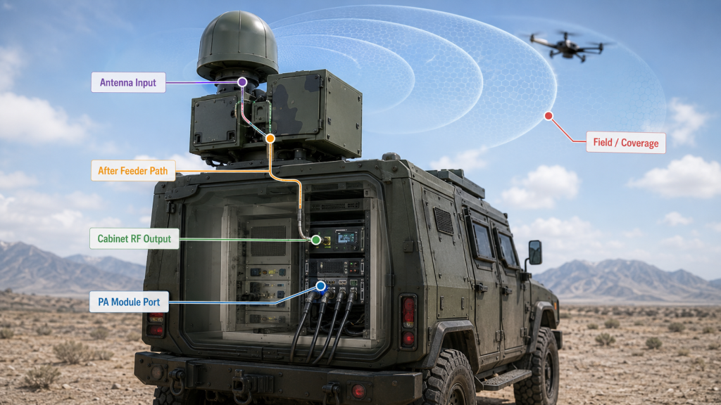
Port, cabinet, feeder, and antenna points are different Vehicle C-UAS RF power measurement boundaries inside the same installed RF chain. The PA module port is the amplifier reference, the cabinet RF output is the integration boundary, the feeder end shows delivery through the vehicle path, and the antenna input shows installed RF delivery before radiation.
Here’s the new point that many RFQ documents miss: vehicle systems often need a middle boundary. That boundary is usually the cabinet RF output or bulkhead output, where the module supplier, cabinet integrator, and vehicle team can agree on a practical handover point.
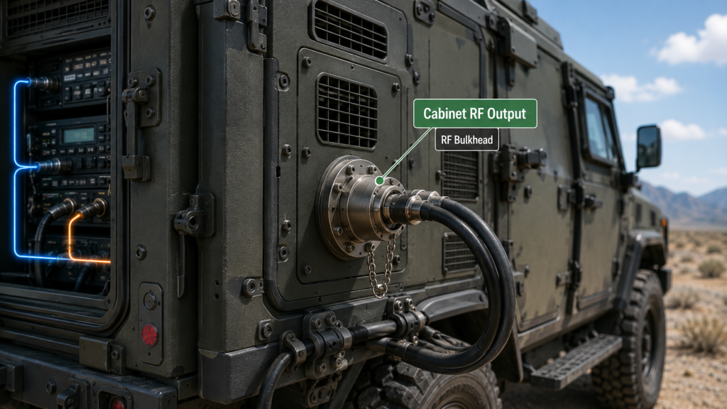
Why Add a Cabinet Output Point?
A cabinet output point matters because the PA module port may not be accessible after final assembly. The module may sit inside a sealed equipment bay, behind thermal plates, RF jumpers, power wiring, fans, control cables, and protection covers.
A cabinet output point helps define:
- What the module-and-cabinet assembly delivers
- Whether internal RF routing is acceptable
- Where supplier responsibility ends
- Where vehicle feeder responsibility begins
- How field teams can retest without opening the cabinet
How Should These Points Be Named?
Once the measurement boundary is clear, cable-path loss can be reviewed separately. The key point here is to avoid mixing PA-port, cabinet-output, feeder-end, and antenna-input readings in the same acceptance discussion.
Key Takeaway: A vehicle C-UAS system should define at least three RF power boundaries: PA module port, cabinet output, and antenna feed.
| Measurement Point | What It Shows | What It Does Not Show |
|---|---|---|
| PA module port | Amplifier output capability | Cabinet routing or antenna path |
| Cabinet RF output | Integrated cabinet delivery | Roof feeder or antenna condition |
| Feeder end | Cable-path delivery | Antenna matching after connection |
| Antenna input | Installed RF delivery | Antenna radiation pattern |
| Field effect | Operational result | Exact RF loss location |
This table gives each team a shared vocabulary before the acceptance test starts.
4. How to Evaluate Thermal and Duty Cycle Impact on Antenna Power
Vehicle layout should define the measurement plane because Vehicle C-UAS RF power testing depends on where engineers can measure, service, and repeat the result after installation. The PA module may be placed where cooling and power distribution are practical, while antennas are placed where RF coverage and platform geometry require them.
This is where vehicle systems differ from bench systems. The best RF position, the best thermal position, and the best service position are rarely the same.
What Layout Details Change the Test Boundary?
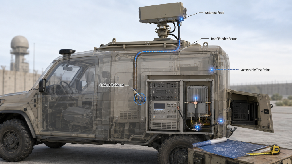
Layout details change the test boundary when they make one point easier, safer, or more repeatable than another. In a roof-mounted or mast-mounted antenna layout, the cabinet RF output may be the only repeatable service point after installation, while antenna-feed access may require opening weatherproof joints or roof hardware.
Review these layout details early:
- PA location inside rack, cabinet, or equipment bay
- Cabinet RF bulkhead position
- Cable route to roof, mast, or antenna bracket
- Service access after vehicle assembly
- Whether antenna feed points remain accessible
- Whether multiple bands use identical boundary definitions
- Whether field retest can be done without disassembly
What Should Be Marked in the Drawing?
The drawing should mark RF power measurement planes before the vehicle build is locked. This avoids late arguments about whether the accepted value belongs to the PA, the cabinet output, the feeder path, or the antenna input.
Key Takeaway: Vehicle layout should not only show cable routing; it should show where RF power will be measured, accepted, and retested.
| Layout Condition | Measurement Risk | Better Definition |
|---|---|---|
| PA hidden after assembly | Port retest becomes difficult | Define cabinet RF output |
| Antenna feed sealed later | Field team cannot verify feed power | Add accessible test boundary |
| Roof antenna far from cabinet | Antenna-feed value differs | Separate feeder-path review |
| Multiple antenna mounts | Boundary may vary by channel | Label each measurement plane |
| Cabinet output unmarked | Teams may test different points | Mark bulkhead reference point |
This table helps mechanical, RF, and field teams agree on test access before the vehicle layout becomes expensive to change.
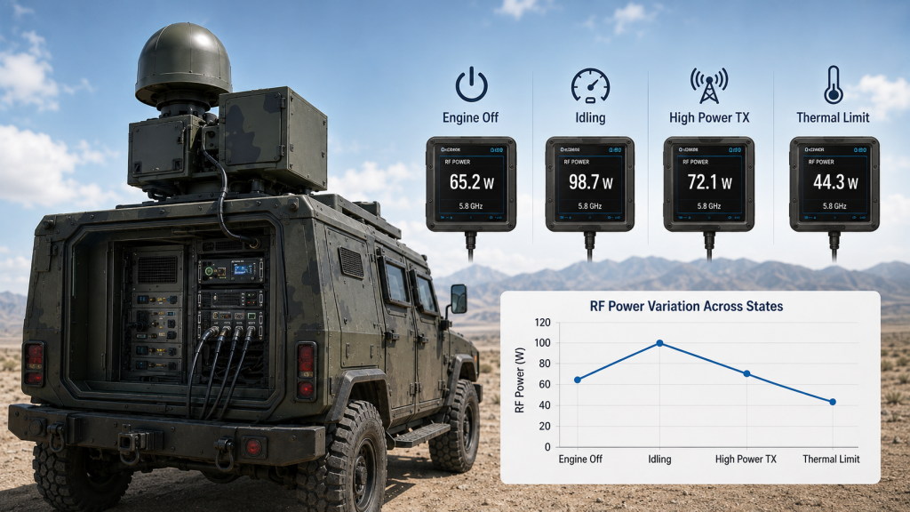
5. Why Do Engine-On and Full-Load Tests Change Readings?
Engine-on and full-load tests change readings because Vehicle C-UAS RF power measurement depends on vehicle operating state as much as measurement position. A reading taken with one channel on and engine off may not match a reading taken with all PA channels running, alternator active, cabinet closed, and the system already warm.
Here’s the field reality: the measurement point is only half the definition. The vehicle state is the other half.
Which Vehicle States Should Be Recorded?
Vehicle states should be recorded because RF output can change when the electrical and thermal environment changes. This matters especially in multi-module C-UAS cabinets where several bands may operate at high duty cycle.
Record these conditions:
- Engine off or engine on
- Battery-only or alternator-supported power
- Single-channel or all-channel operation
- Warm-up time before measurement
- Cabinet door open or closed
- Ambient temperature around the cabinet
- DC voltage at supply and module side
- Alarm status during the reading
Why Does Full-Load Testing Matter?
Full-load testing matters because the accepted reference plane should remain meaningful under mission-like conditions. In Low-Altitude Security & C-UAS EW Solutions, an output value that looks stable during a short single-channel test may not represent the vehicle system during simultaneous multi-band operation.
Key Takeaway: A valid RF power measurement must state both the reference plane and the vehicle operating state.
| Vehicle State | What May Change | What to Record |
|---|---|---|
| Engine off | Battery voltage sag | DC voltage at module side |
| Engine on | Alternator behavior | Supply condition during RF output |
| Single channel on | Lower heat and current | Channel count during test |
| All channels on | Higher thermal and DC stress | Full-load duration |
| Cabinet open | Better cooling than real use | Door state and airflow |
This table prevents a clean setup reading from being mistaken for a mission-ready result.
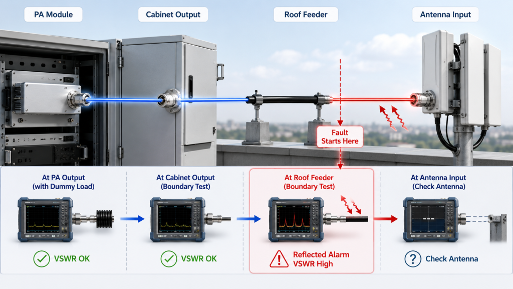
6. What Protection Logic and VSWR Reveal About Usable RF Power
VSWR alarms can locate the wrong boundary in Vehicle C-UAS RF power testing when the test sequence adds one RF segment at a time. If module-port testing with a known load is stable, but the alarm appears after cabinet routing, roof feeder, or antenna connection, the alarm helps show where the problem begins.
The point here is not to repeat VSWR theory. The value of VSWR feedback is diagnostic: it helps engineers decide which boundary should be tested next.
How Should Alarm Data Be Read?
Alarm data should be read together with the measurement point. A low wattage number alone may look like weak output, but a low wattage number plus reflected-power alarm gives a different diagnosis.
Use alarm feedback to ask:
- Did the alarm appear at module-port testing?
- Did it appear only after cabinet RF routing?
- Did it appear only with the roof feeder attached?
- Did it appear only with the real antenna?
- Did it repeat at the same frequency band?
- Did it appear after vibration, heat, or movement?
Why Test One Boundary at a Time?
Testing one boundary at a time matters because a fully connected system can tell you a problem exists, but not where it starts. If the PA, cabinet, feeder, bulkhead, antenna, and controller are all connected at once, the alarm may be real while the fault location remains unclear.
Key Takeaway: VSWR alarms should be used as boundary-location evidence, not as automatic proof of PA weakness.
| Alarm Pattern | Likely Boundary | Better Next Test | What Not to Assume |
|---|---|---|---|
| Alarm on dummy load | PA or test setup | Recheck module-port setup | Antenna path is guilty |
| Alarm after cabinet output | Internal RF path | Test cabinet jumper and bulkhead | PA is underpowered |
| Alarm after roof feeder | Vehicle feeder path | Test cable and connectors | Wattage rating is wrong |
| Alarm only with antenna | Antenna match or mount | Verify antenna VSWR in place | PA is bad |
| Alarm after movement | Mechanical instability | Inspect vibration points | Result is random |
This table helps engineers move from “output is low” to “the issue starts after this boundary.”
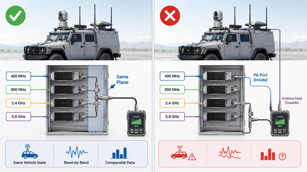
7. How Should Wideband Channels Be Compared Point by Point?
Wideband channels should be compared point by point by using the same Vehicle C-UAS RF power reference plane, vehicle state, and test condition for each band. Comparing one band at the PA module port and another band at the antenna feed creates misleading output conclusions.
Here’s the selection risk: a wideband system can look uneven simply because the measurement boundary changed between channels.
Why Does Reference Consistency Matter by Band?
Reference consistency matters because C-UAS systems often include low, mid, and high frequency paths with different antennas, cable lengths, connector types, cabinet routes, and thermal loads. If each band is measured at a different point, the table becomes a path comparison rather than a channel comparison.
Keep these items consistent:
- Same reference plane definition
- Same power meter method
- Same vehicle state
- Same load type category
- Same warm-up rule
- Same channel-on condition
- Same report field names
What Should Wideband Reports Avoid?
Wideband reports should avoid mixing a clean module-port value for one band with an antenna-feed value for another band. That kind of report may look complete, but it cannot support engineering approval.
If different points must be used because of physical access, the report should state the reason and avoid ranking the bands as if the data came from the same boundary.
Key Takeaway: Wideband RF power data is only comparable when every band uses the same measurement boundary or clearly states why it does not.
| Comparison Method | Result Quality | Why |
|---|---|---|
| All bands at PA port | Good for PA comparison | Same amplifier reference |
| All bands at cabinet output | Good for cabinet acceptance | Same integration boundary |
| All bands at antenna feed | Good for installed delivery | Same system boundary |
| Mixed port and antenna data | Weak | Boundary changes the number |
| Field effect only | Incomplete | Antenna and site factors included |
This table protects wideband channel comparison from hidden reference-plane errors.
8. What Should a Repeatable Vehicle RF Test Report Record?
A repeatable vehicle RF test report should record the measurement plane, vehicle state, load condition, frequency, DC condition, thermal condition, alarm status, and serial-number identity behind every Vehicle C-UAS RF power result. A report that only says “100W passed” does not create a usable retest baseline.
This is where report quality becomes engineering value. The report should allow another engineer to repeat the same judgment later, not only confirm that a delivery document exists.
Which Fields Make the Report Reproducible?
The report becomes reproducible when it captures the factors that change the reading. This matters because vehicle C-UAS output can change with test boundary, operating state, and load condition.
A useful report should include:
- Module S/N
- Cabinet or system S/N if applicable
- Frequency point or band
- Input drive condition
- DC voltage at relevant point
- Measurement plane
- Load type
- Cable or cabinet path condition
- Vehicle state
- Warm-up time
- Ambient or module temperature
- Alarm and status feedback
- Instrument or method reference
For projects that use One Report One Unit as delivery evidence, the report should identify whether the recorded output belongs to the module S/N alone, the cabinet assembly, or the installed vehicle path. Otherwise, S/N traceability may prove the PA module but still fail to explain the vehicle acceptance result.
What Makes One Report One Unit Useful?
One Report One Unit is useful when it becomes a baseline for future retesting, troubleshooting, batch comparison, and acceptance discussion. It should not be only a pass/fail sheet.
As a source factory for RF Power Amplifier modules and C-UAS core components, RF SKYPOWER can align module test records, S/N tracking, cabinet-side review, and customer-side retest conditions so both sides compare matched data instead of disconnected wattage claims.
Key Takeaway: A repeatable report must document the boundary and condition behind the wattage number.
| Report Field | Weak Version | Strong Version |
|---|---|---|
| Output power | 100W passed | 100W at stated measurement plane |
| Test point | Output | PA port, cabinet output, or antenna feed |
| Vehicle state | Not stated | Engine state, channel count, cabinet state |
| Load | Not stated | Dummy load, cabinet path, or antenna |
| Supply | 28V nominal | Voltage under measured condition |
| Traceability | Batch passed | S/N-level One Report One Unit |
This table turns the report into an engineering baseline instead of a delivery formality.
9. What RFQ Details Ensure Accurate Module and Antenna Power
RFQ questions prevent power reference confusion when Vehicle C-UAS RF power requirements define where output is required, where output is measured, and under which vehicle state the result must hold. A request for “100W module” is not the same as a request for “100W at cabinet output” or “target power at antenna feed.”
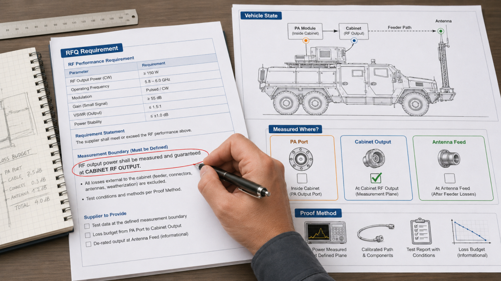
Here’s the better RFQ habit: write the measurement point into the requirement line.
What Should the RFQ State?
The RFQ should state the target output boundary, not only the rated module power. This makes early supplier discussion more accurate and reduces redesign after vehicle layout is fixed.
Use requirement wording like:
- Required output: ___ W at PA module port
- Required output: ___ W at cabinet RF output
- Required output: ___ W estimated or measured at antenna feed
- Vehicle state: engine off / engine on / full-load operation
- Channel condition: single channel / all channels active
- Test load: dummy load / installed path / antenna
- Report requirement: S/N-level measurement plane included
What Should Engineers Ask Before Quotation?
Engineers should ask whether the quoted wattage refers to a module, cabinet, or installed path. If the supplier cannot answer that clearly, the RFQ is not yet specific enough for engineering approval.
A stronger RFQ also asks how the power requirement changes across deployment scenarios. An airport perimeter platform, a mobile tactical vehicle, and a critical infrastructure system may all use RF modules, but their accepted boundary, vehicle state, and retest access can differ. For an airport-specific deployment reference, the Airport Low-Altitude Security Case Study shows why controlled deployment evidence matters beyond a single wattage claim.
Key Takeaway: A clear RFQ defines the required wattage, reference plane, vehicle state, and proof method in the same requirement.
| RFQ Question | Why It Prevents Confusion | Better Wording |
|---|---|---|
| Where is output measured? | Defines the reference plane | “At PA port or cabinet output?” |
| What vehicle state applies? | Controls DC and thermal variables | “Engine on, all channels active?” |
| What load is used? | Separates dummy load and antenna path | “50Ω load or installed antenna?” |
| What report is provided? | Supports retest | “S/N-level report with test point?” |
| What is accepted by customer? | Avoids late disputes | “Which point is the acceptance boundary?” |
This table can be copied into RFQ review before procurement or technical approval.
10. How Do You Approve Usable RF Output Without Guesswork?
You approve usable RF output without guesswork by defining the Vehicle C-UAS RF power measurement plane first, testing under the correct vehicle state, and linking the result to repeatable report evidence. The safest decision is not to chase the highest PA wattage; it is to approve the output boundary that the system must actually meet.
The final decision sequence is simple: define the target point, test the same point, and record the conditions that made the result valid.
What Approval Sequence Works Best?
The approval sequence should start from the system boundary required by the project. If the customer needs an antenna-feed value, do not approve the system only from module-port data. If the contract accepts cabinet output, do not mix it later with roof-antenna readings.
Use this sequence:
- Define the accepted RF power boundary
- Mark the boundary in drawings and reports
- Define vehicle operating state
- Measure module-port power as PA baseline
- Measure cabinet output as integration baseline
- Measure antenna-feed power when required
- Read alarm status during the test
- Compare only matching reference planes
- Attach S/N-level report evidence
- Use deviations to locate the next boundary
For long-duty or harsh-site approval, the Critical Infrastructure Counter-UAS Case Study can be used as a scenario reference for why output claims should be supported by field-ready evidence, not only catalog numbers.
When Should RF SKYPOWER Join the Review?
RF SKYPOWER should join early when the project involves multiple bands, high duty cycle, vehicle cabinets, antenna separation, strict acceptance wording, or repeatable test evidence. Early review can align frequency range, PA output target, cabinet boundary, antenna path, DC supply, protection feedback, and report format before hardware decisions become expensive to change.
Key Takeaway: Usable RF output approval should be based on a named measurement plane, not an assumed wattage label.
| Approval Condition | Correct Decision | Avoid This Mistake |
|---|---|---|
| Module acceptance | Use PA port data | Calling it antenna power |
| Cabinet acceptance | Use cabinet RF output | Ignoring internal RF routing |
| Installed-path acceptance | Use antenna-feed value | Blaming PA before path check |
| Wideband comparison | Match reference planes | Mixing band test points |
| Batch delivery | Require S/N evidence | Comparing unmatched reports |
This table gives the final review team a practical way to approve RF output without confusing module, cabinet, feeder, and antenna boundaries.
FAQ
Can I use module-port power as the vehicle C-UAS output value?
Yes, but only if the contract clearly defines the PA module port as the accepted output boundary. If the project requires cabinet output or antenna-feed power, module-port power should be treated as a PA baseline, not the final vehicle system value.
How do I know whether two RF power readings are comparable?
Two readings are comparable only when they use the same measurement plane, frequency, load type, vehicle state, channel condition, and thermal condition. If any of those changed, both readings may be correct but still unsuitable for direct comparison.
What is the best measurement point for vehicle C-UAS acceptance?
The best measurement point depends on the contract boundary. Module-port power is best for PA acceptance, cabinet RF output is best for integrated cabinet acceptance, and antenna-feed power is best for installed-path validation.
What should an RF power acceptance line say in the contract?
It should state the required wattage, measurement plane, frequency band, load condition, vehicle state, channel condition, and report evidence. For example: “Required output: ___ W at cabinet RF output, engine on, all channels active, measured after warm-up.”
What should I check before blaming the PA module?
First check whether the measurement point changed. Then review cabinet output, feeder path, antenna load, DC voltage, vehicle state, alarm feedback, and whether the test was repeated under the same conditions.
Conclusion
Defining RF power measurement points helps vehicle C-UAS teams avoid one of the most expensive acceptance problems: comparing correct wattage numbers from different places in the system. A PA module port value, cabinet RF output value, feeder-end value, antenna input value, and field-effect result all describe different parts of the same RF chain. They should not be treated as interchangeable.
This article showed how to separate those boundaries, when module-port power is still useful, why cabinet output should often be added as a handover point, how vehicle state changes readings, how VSWR alarms help locate the wrong boundary, and what RFQ wording prevents reference confusion. The final rule is straightforward: name the measurement plane before judging the power.
RF SKYPOWER supports vehicle C-UAS integrators with RF Power Amplifier modules, source-factory engineering review, S/N-level test evidence, and practical discussion around module output, cabinet boundaries, antenna paths, control feedback, and acceptance reports. To review your RF output requirement or define the correct measurement boundary for a vehicle-mounted C-UAS project, contact us today.
Field-ready C-UAS systems are approved by measured reference points, not by unclear wattage claims.