


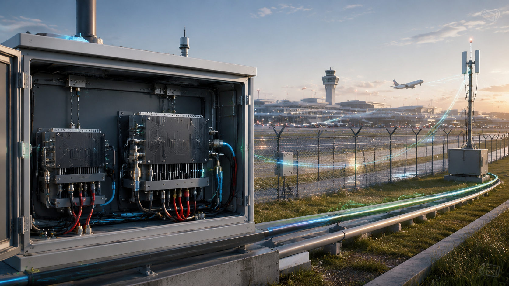
RF Power Amplifier Selection between 100W and 200W for a C-UAS system should start from the installed airport RF chain, not from the PA watt label alone. Engineers should compare the target antenna-end power, feeder path, thermal margin, 28V supply capacity, duty cycle, protection behavior, and acceptance method before choosing either module class. A 200W module is justified when the same antenna path needs more usable output and the cabinet, supply, cooling, antenna load, and control logic can support it. A 100W module can be the stronger engineering decision when it already meets the required antenna-end result with lower heat, lower current demand, and more stable long-duty operation.
The central conflict is simple: higher PA wattage increases output capability, but the full airport C-UAS RF chain decides whether that extra output becomes stable, usable, and repeatable system performance.
For airport perimeter engineers, the real decision is not “Which module has the bigger label?” The better question is: under the same antenna path, does moving from 100W to 200W create enough usable output to justify the added current, heat, reflected-power risk, cabinet pressure, and acceptance burden?
1. How to Avoid Oversized RF Power Amplifier Selection
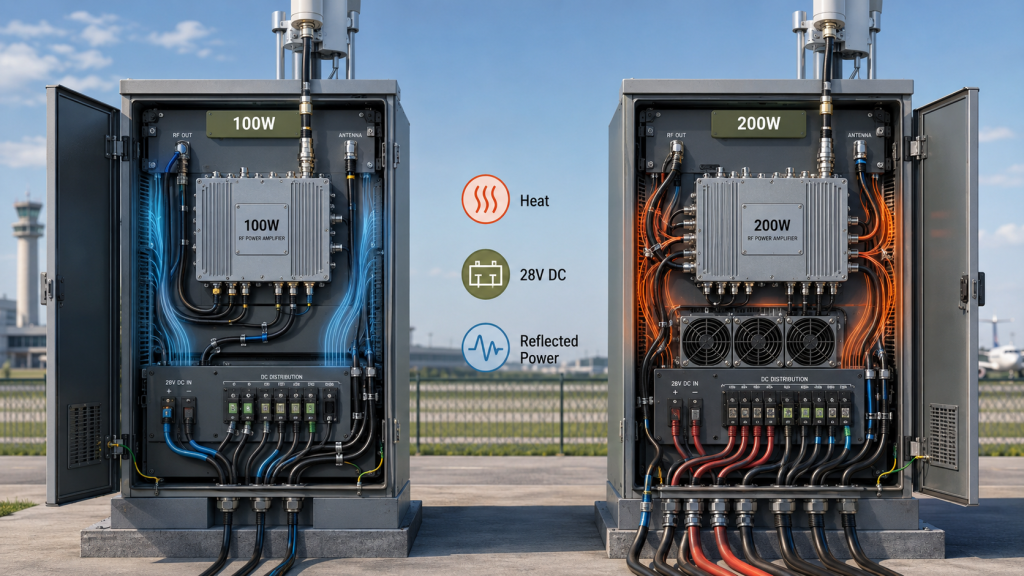
200W is not automatically better than 100W because 100W vs 200W RF Power Amplifier selection depends on whether the full C-UAS RF chain can use the extra output. A 200W PA may produce more power at the module port, but that extra capability still has to pass through the same feeder path, connectors, antenna load, cabinet environment, and protection logic.
Here’s the engineering point: higher output changes more than the RF number. It increases DC current demand, heat load, connector stress, reflected-power exposure, and the need for clearer alarm feedback.
What Misleads Buyers About Higher Wattage?
The mistake is treating 200W as a safer default. In an airport perimeter C-UAS system, a larger PA can be valuable, but only when the system has enough margin to support it continuously.
Before assuming 200W is better, check:
- Can the antenna path carry higher power without heating or mismatch?
- Can the cabinet remove the additional heat?
- Can the 28V supply hold voltage under full RF load?
- Does reflected power stay below the protection boundary?
- Can the system log alarm status during the 200W test?
- Does acceptance require PA-port output or antenna-end output?
Key Takeaway: The better PA is not the higher-watt PA; it is the power level the airport C-UAS system can use continuously and verify reliably.
| Wrong Assumption | Better Check | Selection Risk |
|---|---|---|
| 200W is always safer | Check full-system margin | Extra heat and alarms |
| 100W is always weak | Check target antenna-end power | Oversized system design |
| More watts fix path loss | Review the installed RF chain | Loss or mismatch may remain |
| Peak output proves value | Test long-duty stability | Short-test approval only |
| Bigger PA reduces risk | Review protection feedback | Harder fault diagnosis |
This table helps engineering teams avoid selecting PA power before confirming whether the system can actually use it.
2. What Makes 100W Practical for RF Power Amplifier Selection
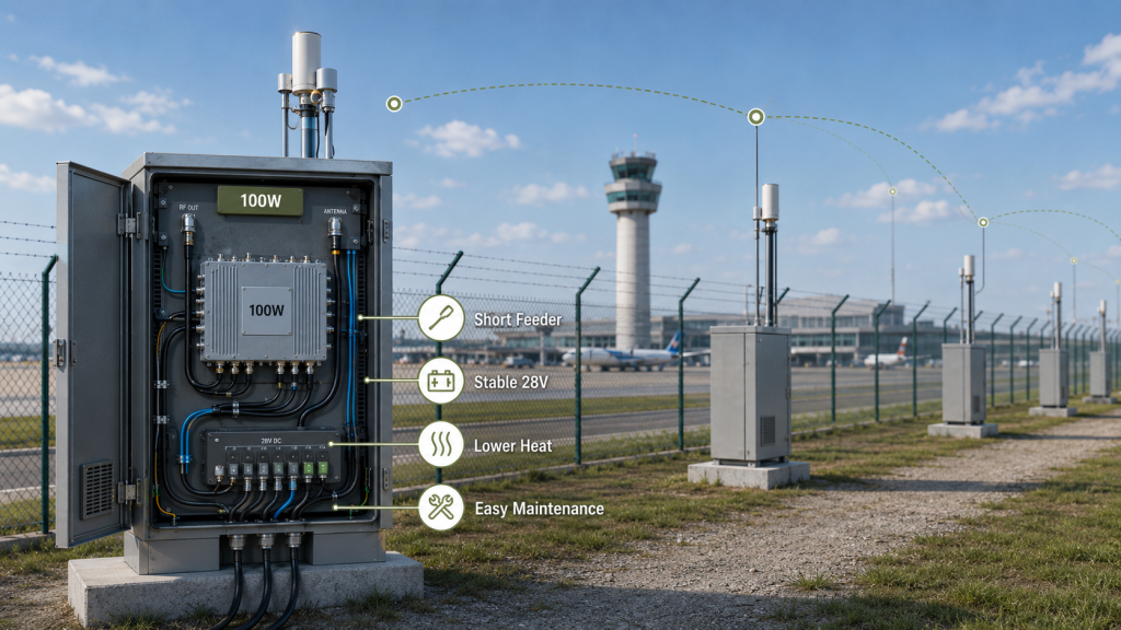
100W is the more practical airport choice when 100W vs 200W RF Power Amplifier selection shows that the target antenna-end output is already met with lower heat, lower current demand, and more stable long-duty operation. In that case, 100W is not a weak option; it is a balanced system choice.
The practical risk is clear: choosing 200W only because it feels safer can create a system that is harder to cool, harder to power, and harder to keep stable during continuous operation.
Which Conditions Make 100W More Suitable?
100W is often more suitable when the airport perimeter uses multiple antenna points or shorter feeder paths. It can also be the better choice when the cabinet has limited cooling capacity or when several modules must operate at the same time.
Look for these conditions:
- Distributed antenna points around the airport perimeter
- Short or controlled feeder path
- Target antenna-end power already confirmed
- Long-duty operation is more important than peak output
- Outdoor cabinet heat is a major constraint
- 28V supply reserve is limited
- Multiple RF channels operate together
- Low alarm rate is important for remote maintenance
For teams comparing RF Power Amplifier modules for C-UAS integration, 100W should be reviewed as a real engineering option rather than a budget fallback.
Key Takeaway: Choose 100W when it meets antenna-end output with better thermal margin, supply margin, and repeatable long-duty stability.
| Selection Condition | Why 100W May Fit | What to Confirm |
|---|---|---|
| Distributed perimeter layout | Lower power per point works | Sector coverage target |
| Short feeder path | Less PA margin needed | Antenna-end result |
| Limited cabinet cooling | Lower heat load | Full-duty temperature |
| Limited 28V reserve | Lower current demand | Module-side voltage |
| Strict alarm tolerance | Lower protection pressure | VSWR and thermal status |
This table shows when 100W is the practical system decision, not a reduced-performance compromise.
3. What Makes 200W Necessary for RF Power Amplifier Selection
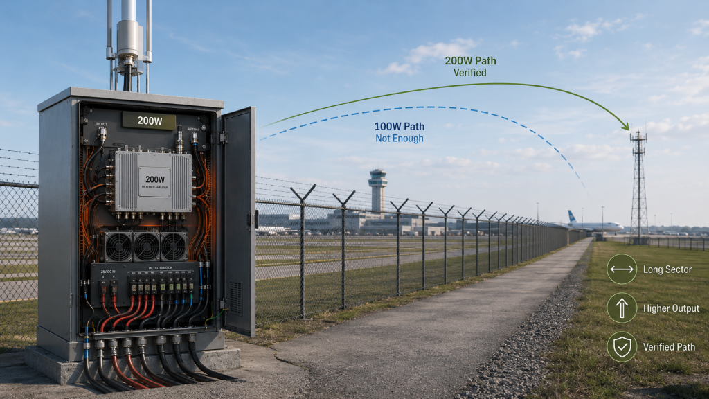
200W becomes a real system requirement when 100W vs 200W RF Power Amplifier selection shows that 100W cannot meet the target antenna-end output under the same airport RF chain. The higher-power module is justified only when the system can also support the added current, heat, load, and protection stress.
This is where system integrators should pay attention: 200W should solve a measured output gap, not replace basic RF path review.
What Conditions Justify 200W?
200W is more reasonable when the airport layout limits antenna placement, when the required coverage sector is larger, or when the same antenna path creates enough loss that 100W cannot reach the accepted output target.
Common triggers include:
- Longer perimeter sector coverage
- Limited antenna mounting points
- Higher required antenna-end output
- Known feeder and connector loss
- High-frequency paths with higher loss
- Hot-state output margin requirement
- Customer acceptance requiring higher delivered power
- Cabinet, supply, cooling, and antenna load already designed for 200W
A 200W module should not be used to hide a poor antenna path. If the path is lossy, weak, or mismatched, the better first step is to define the path condition before increasing PA power.
Key Takeaway: Choose 200W when the system truly needs more usable output and the RF chain can sustain the added pressure.
| 200W Trigger | Required Evidence | Risk If Missing |
|---|---|---|
| 100W misses target | Antenna-end measurement | Overbuying power |
| Few antenna locations | Layout review | Treating power as a layout fix |
| High feeder loss | Path-loss data | Heating lossy components |
| Hot cabinet operation | Thermal test | Derating after warm-up |
| Higher acceptance target | Test-point definition | Comparing the wrong boundary |
This table ties 200W selection to measurable system need instead of general preference.
4. How to Judge RF Power Amplifier Selection by RF Path
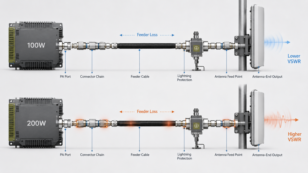
The same antenna path changes 100W vs 200W RF Power Amplifier selection because both modules must pass through the same feeder cable, connector chain, antenna load, mounting condition, and protection boundary. The comparison is not only about which PA produces more power; it is about how much extra usable output survives the same path.
Here’s the practical point: the same feeder path may work safely at 100W but become hotter, more sensitive, or less stable at 200W. Extra PA power is only useful if the path can carry it without turning the upgrade into reflected power, thermal stress, or protection events.
What Should Be Compared Under One Path?
Under the same antenna path, compare delivered and stable output, not only module-port output. A higher module number does not automatically mean the accepted boundary receives a proportional increase.
Compare these items:
- PA-port output
- Cabinet or feeder-end output
- Antenna-end output
- Reflected power
- Connector temperature
- VSWR status
- Alarm behavior
- Long-duty stability
For long roof runs, fence-line cable routes, or high-frequency paths, RF Power Amplifier feeder cable loss should be part of the 100W vs 200W decision before the cabinet layout is locked.
Key Takeaway: Under the same antenna path, the real question is how much extra usable output reaches the accepted boundary.
| Same-Path Condition | 100W Result | 200W Result | Better Judgment |
|---|---|---|---|
| Low path loss | May meet target | Adds margin | Check whether margin is needed |
| High path loss | May fall short | May help | Confirm path can carry power |
| Poor antenna match | Lower stress | Higher reflection risk | Fix load first |
| Weak connector chain | May pass | May heat or drift | Upgrade path before PA |
| Stable full-load path | Predictable | Higher usable output | 200W can be justified |
This table keeps the comparison inside the installed RF chain instead of turning it into a catalog wattage debate.
5. What Do Airport Perimeter Deployments Reveal?
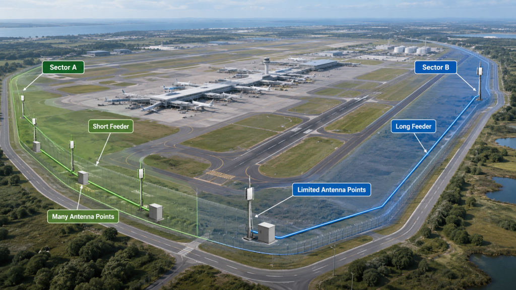
Airport perimeter deployments reveal that 100W vs 200W RF Power Amplifier selection depends on antenna point layout, feeder route, maintenance access, target antenna-end power, and whether higher PA output improves usable coverage without adding instability. There is no single airport-wide answer.
Here’s the field reality: one airport may contain several different RF conditions. A fence-line sector with short feeders and multiple antenna points may favor 100W, while a constrained rooftop or remote sector may justify 200W.
How Do Layout and Maintenance Change the Choice?
Airport perimeter design must balance coverage, service access, cable routing, weather exposure, and remote maintenance. The power level should follow that physical design.
Review these deployment factors:
- Number of antenna points
- Cabinet-to-antenna distance
- Available power at each cabinet
- Outdoor cabinet temperature
- Maintenance access after installation
- Single-sector vs multi-sector coverage
- Remote monitoring and alarm handling
- Acceptance target per direction
In an airport counter-UAS RF deployment, the PA module, antenna path, control behavior, and acceptance evidence need to work together. A module that looks strong alone may still be the wrong choice for a specific perimeter sector.
Key Takeaway: Airport perimeter power selection should be made by sector and RF path, not by assuming one wattage fits the whole site.
| Deployment Condition | Likely Better Starting Point | Why |
|---|---|---|
| Many antenna points | 100W review | Distributed coverage reduces stress |
| Few mounting locations | 200W review | Higher per-point output may be needed |
| Long feeder route | Path review first | PA upgrade may not solve all loss |
| Remote maintenance | Stability first | Fewer alarms reduce service burden |
| Multi-band cabinet | Band-by-band review | One wattage may not fit all paths |
This table helps airport teams choose by installation condition rather than site size alone.
6. What System Stress Changes RF Power Amplifier Selection
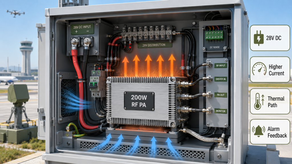
200W changes thermal and supply pressure because 100W vs 200W RF Power Amplifier selection changes the energy entering the module, the heat leaving the module, and the protection behavior the controller must manage. A 200W PA is not simply a stronger version of 100W; it is a higher-load system component.
The selection risk appears here: a project may approve 200W at the RF level, then discover that the power rail, airflow path, mounting plate, connector chain, or alarm logic cannot support it during full-load operation.
What Must Be Verified Before Approving 200W?
Approving 200W requires more than checking the RF output number. The cabinet and power system must be reviewed under the same duty cycle expected in the airport system.
Check these system areas:
- 28V supply current reserve
- Module-side voltage under RF load
- Power cable and terminal capacity
- Heat sink or conduction path
- Cabinet airflow
- Connector power handling
- Temperature alarm behavior
- Multi-module simultaneous operation
For outdoor or hot-site cabinets, RF Power Amplifier output at 50°C should be considered before assuming the 200W rating will remain available during long-duty operation. The same approval should include stable RF Power Amplifier supply voltage under full RF load.
Key Takeaway: 200W is a system-level power decision because it increases electrical, thermal, mechanical, and control requirements.
| System Area | 100W Pressure | 200W Pressure | What to Verify |
|---|---|---|---|
| 28V supply | Moderate | Higher current | Module-side voltage |
| Cabinet thermal path | Easier | More heat load | Full-duty temperature |
| Connectors | Lower stress | Higher stress | Heating and mismatch |
| Control logic | Simpler | More protection events possible | Alarm categories |
| Multi-module operation | Easier to support | Higher total load | Simultaneous test |
This table shows why 200W approval should involve RF, power, thermal, and control teams together.
7. Why Do Wideband and Band-Edge Results Matter?
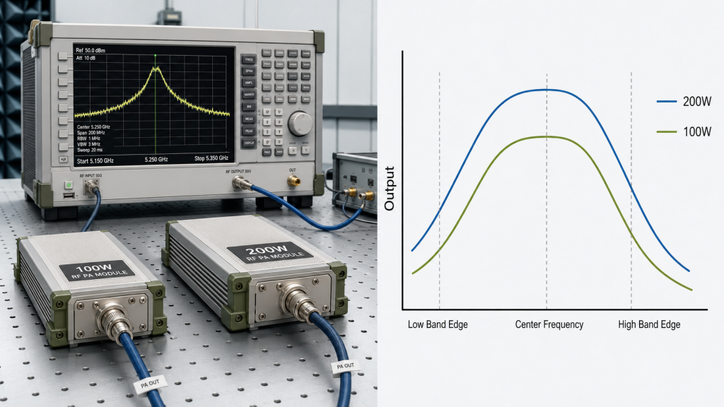
Wideband and band-edge results matter because 100W vs 200W RF Power Amplifier selection must be based on usable output across the required airport bands, not one strong center-frequency number. A module that looks excellent at one point may not be the better choice across the full target range.
The better check is simple: compare the power class where the airport system must actually operate. The weakest required band or band edge can decide the practical module choice.
What Should Be Checked Across the Band?
The review should confirm whether 100W or 200W remains useful across the real frequency range. Peak output is not enough if the required band edge is weak or unstable.
Check these items:
- Center-frequency output
- Band-edge output
- Gain flatness trend
- Hot-state behavior by band
- Antenna match by band
- Feeder loss by frequency
- Protection status at weaker points
For multi-band projects, C-UAS wideband RF Power Amplifier verification helps prevent one comfortable frequency point from hiding weak-band performance.
Key Takeaway: The best power level is decided by the weakest required frequency, not the strongest single test point.
| Band Condition | Selection Risk | Better Check |
|---|---|---|
| Strong center frequency | False confidence | Test band edges |
| Weak high band | Lower delivered output | Review path and PA margin |
| Uneven wideband output | Coverage inconsistency | Compare full-band data |
| Hot-state band drift | Long-duty failure | Retest after warm-up |
| 200W only strong at one point | Misleading upgrade | Check usable band range |
This table helps engineers compare power classes by required-band performance instead of headline wattage.
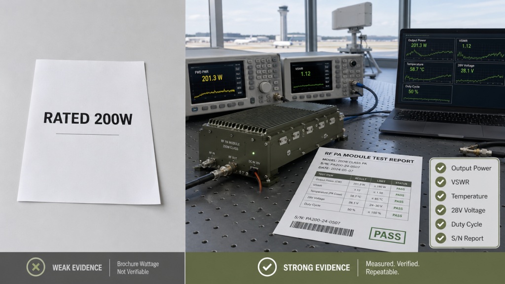
8. How Should Evidence Compare 100W and 200W?
Evidence should compare 100W and 200W by output power, reflected power, temperature, voltage, current, alarm status, load condition, duty cycle, and repeatable test point. A 100W vs 200W RF Power Amplifier comparison that only lists rated wattage does not prove which module is better for the airport system.
This is where acceptance evidence matters. A 200W module that reaches peak output briefly but triggers thermal, VSWR, or voltage alarms during long-duty operation may be less useful than a 100W module that stays stable at the accepted boundary.
What Should the Test Record Include?
The test record should explain what was measured, where it was measured, and what the module condition was during the comparison. Without that context, the higher number may hide the higher risk.
Record these fields:
- PA output power
- Antenna-end or accepted-boundary power
- Forward and reflected power
- VSWR status
- Module temperature
- Module-side voltage
- Current draw
- Load condition
- Duty cycle
- Alarm behavior
- S/N and report identity
Before selecting 200W, RF Power Amplifier VSWR protection should be reviewed under the same antenna load, because reflected-power stress may appear only after the higher-power path is tested.
Key Takeaway: 100W and 200W should be compared by stable evidence, not by a single rated output number.
| Evidence Item | Weak Comparison | Strong Comparison |
|---|---|---|
| Output power | Peak wattage only | Same test point and duty cycle |
| Reflected power | Not recorded | Logged with load condition |
| Temperature | Not stated | Recorded during long-duty test |
| Voltage/current | Supply label only | Measured under RF load |
| Alarm status | Ignored | Used to judge stability |
| Report evidence | Generic pass sheet | S/N-linked repeatable record |
This table turns the 100W vs 200W comparison into an acceptance decision, not a brochure comparison.
9. What Should Engineers Ask Before Quotation?
Engineers should ask for system conditions before quotation because 100W vs 200W RF Power Amplifier selection cannot be judged from wattage alone. If an RFQ only says “quote 100W and 200W PA modules,” the supplier can price modules but cannot judge which power level fits the airport system.
Here’s the practical checklist: the clearer the antenna path, frequency range, duty cycle, and acceptance target are, the more useful the quotation becomes.
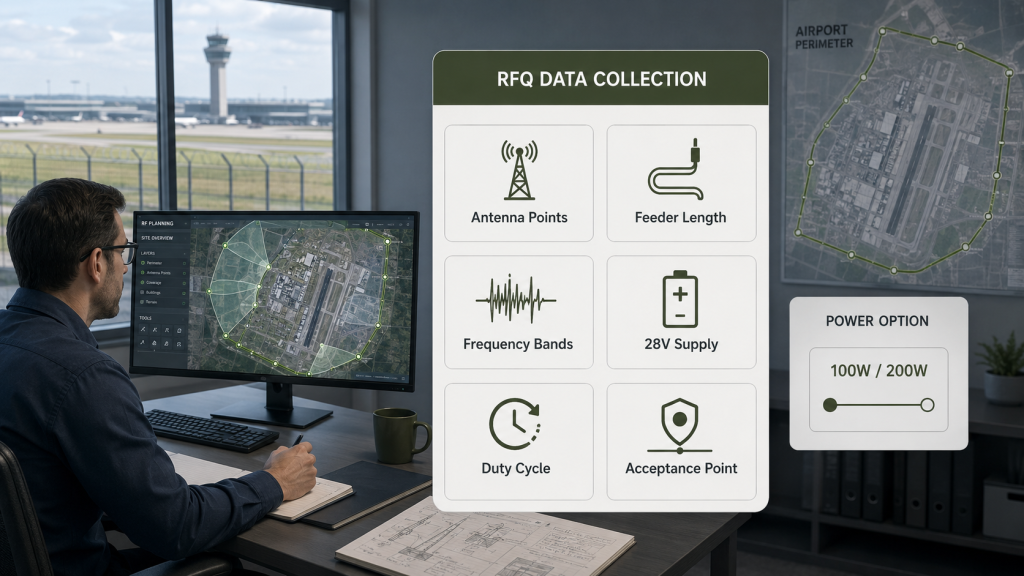
What RFQ Data Changes the Answer?
RFQ data changes the answer because 100W and 200W interact with antenna placement, feeder route, DC supply, cabinet cooling, and protection feedback.
Before quotation, define:
- Airport perimeter target area
- Antenna point quantity
- Antenna mounting position
- Output reference point
- Feeder cable length and type
- Connector and adapter count
- Target frequency bands
- Wideband or narrowband requirement
- Duty cycle and operating profile
- Outdoor temperature range
- Cabinet cooling method
- 28V supply capacity
- Number of modules per cabinet
- Antenna VSWR or return-loss target
- Protection feedback requirement
- Test report and S/N requirement
For Low-Altitude Security & C-UAS EW Solutions, the PA module should be reviewed with the antenna path, power system, cabinet condition, and acceptance method as one working chain.
Key Takeaway: A useful RFQ gives the supplier enough system context to recommend 100W, 200W, or a different architecture.
| RFQ Item | Why It Matters | What It Decides |
|---|---|---|
| Output reference point | Prevents wrong comparison | PA-side or antenna-side target |
| Feeder path | Shows delivery loss | 100W enough or 200W needed |
| Duty cycle | Shows heat pressure | Sustainable output |
| 28V capacity | Shows current margin | Full-load stability |
| Antenna VSWR | Shows load stress | Reflected-power risk |
| Report requirement | Shows proof method | Repeatable acceptance |
This table helps procurement teams move from price comparison to technical selection.
10. How to Finalize RF Power Amplifier Selection
You decide between 100W and 200W by starting from the airport acceptance target, then checking the antenna path, delivered output, thermal margin, 28V supply capacity, duty cycle, wideband behavior, protection status, and report evidence. The right 100W vs 200W RF Power Amplifier selection is the one the system can use, sustain, protect, and verify.
The final decision is not fixed. Some airport perimeter sectors may be better with 100W distributed channels. Others may need 200W because antenna locations are limited or target antenna-end power is higher.
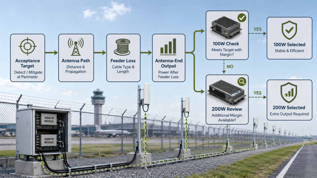
What Decision Sequence Works Best?
A reliable decision sequence starts with the accepted output boundary and works backward. This avoids choosing a larger PA before the system knows whether it needs one.
Use this sequence:
- Define the acceptance target
- Confirm the output reference point
- Check the same antenna path
- Estimate or measure feeder loss
- Verify whether 100W meets antenna-end output
- Test whether 200W adds usable output
- Confirm thermal and 28V supply margin
- Check duty cycle and band-edge behavior
- Review VSWR, reflected power, and alarm status
- Compare S/N-linked test evidence
- Consider whether more antenna points beat higher PA power
As a source factory for RF Power Amplifier modules and C-UAS core components, RF SKYPOWER can support early review when the project must compare 100W and 200W modules under a known airport antenna path.
Key Takeaway: Choose 100W when it meets antenna-end power with better stability and system margin; choose 200W when the chain truly needs more usable output and can support the added pressure.
| Final Condition | Better Choice | Why |
|---|---|---|
| 100W meets accepted output | 100W | Lower heat and current pressure |
| 100W misses antenna-end target | 200W review | Higher usable output may be needed |
| Cabinet cooling is limited | 100W or redesign | 200W may derate |
| Antenna points are limited | 200W review | More per-point output may help |
| Path is lossy or mismatched | Fix path first | Bigger PA may add stress |
| Full evidence supports 200W | 200W | Higher output is usable and repeatable |
This table gives engineers a final decision path without reducing the answer to “bigger is better.”
FAQ
When should I choose 100W RF PA modules for C-UAS?
Choose 100W when the airport antenna path is efficient, the antenna-end output target is already met, and the system benefits from lower heat, lower current demand, and more stable long-duty operation. It is not a weak choice when the RF chain is well designed.
When should I choose 200W RF PA modules for C-UAS?
Choose 200W when 100W cannot meet the target antenna-end output under the same antenna path and the cabinet, supply, cooling, antenna load, protection logic, and acceptance evidence can support the higher power level.
Does 200W double the C-UAS coverage compared with 100W?
No, 200W does not automatically double coverage. Real improvement depends on antenna-end power, feeder loss, antenna pattern, frequency band, installation height, site geometry, protection behavior, and acceptance conditions.
What should I check before upgrading from 100W to 200W?
Check feeder path, antenna match, module-side voltage, current reserve, cabinet cooling, duty cycle, reflected power, alarm status, band-edge behavior, and the measurement point used for acceptance. The upgrade should solve a measured system gap.
Can one airport system use both 100W and 200W modules?
Yes, mixed power levels can be reasonable when different perimeter sectors have different antenna paths, coverage targets, cabinet limits, or frequency requirements. Each power level should be justified by the local RF chain and acceptance target.
Conclusion
Choosing between 100W and 200W RF PA modules for an airport C-UAS system is not a simple wattage comparison. A 200W module can provide valuable extra output when the antenna path, feeder loss, target antenna-end power, cabinet cooling, 28V supply capacity, VSWR behavior, duty cycle, and acceptance method justify it. But if the same RF chain cannot use, cool, power, protect, or verify the extra output, 200W may add integration pressure without improving stable usable performance.
For airport perimeter engineers, the practical decision is clear: start from the installed antenna path and acceptance target. Confirm whether 100W already meets the required antenna-end output with better thermal and supply stability. Choose 200W only when the system truly needs more usable output and the full chain can support the added current, heat, reflected-power risk, and protection feedback.
RF SKYPOWER supports airport perimeter C-UAS projects by reviewing 100W and 200W RF PA module options together with antenna path, feeder loss, band behavior, thermal margin, 28V supply capacity, protection logic, and repeatable acceptance evidence before final integration. To compare your 100W and 200W module options under a real airport RF chain, contact us today.
Field-ready C-UAS power selection starts with verified system capacity, not bigger wattage assumptions.