


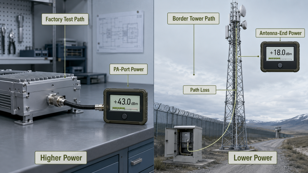
Feeder and connector loss change RF Power Margin because the usable output that matters in a border or coastline C-UAS system is the power remaining at the antenna end, not only the wattage available at the RF Power Amplifier output port. A PA module may deliver the expected output on a short factory test path, yet the real antenna-end power can drop after feeder cable length, connector count, waterproof joints, lightning protection, adapter transitions, cabinet feedthroughs, and outdoor routing are included.
The central conflict is simple: PA-port margin describes module-side reserve, but antenna-end margin describes system-side reserve. For system integrators, RF engineers, and procurement reviewers, the practical choice is not only whether to select a 100W, 150W, or 200W module. The harder question is whether enough RF Power Margin remains after the border tower, coastline mast, outdoor cabinet, or remote antenna path has consumed part of the PA output.
If feeder and connector loss are ignored during selection, the project may look safe on paper and still fail antenna-end acceptance later. The better approach is to define the required antenna-end output first, then work backward through feeder loss, connector loss, outdoor RF transitions, frequency behavior, thermal margin, DC supply margin, and protection status.
1. What Makes PA-Port RF Power Margin Misleading
PA-port margin can mislead border engineers because RF Power Amplifier Power Margin calculated only at the module output connector may disappear before power reaches the antenna input. A module-side wattage number is useful, but it is only the starting point of the installed RF chain. In border and coastline C-UAS systems, the RF path often includes long feeder cables, bulkhead connectors, waterproof joints, lightning protectors, and outdoor antenna mounts.
Here’s the engineering point: a clean PA-port result does not prove that the antenna-end target still has reserve. If the selected module is already close to the required output before path loss is included, the real system may have no usable margin left after installation.
What Does the PA-Port Number Really Show?
The PA-port number mainly shows what the module can deliver under a defined test boundary. That boundary may be a short calibrated cable, a known load, stable 28V DC input, controlled ambient temperature, and a clean connector path.
Before treating that number as field margin, you should check:
- Where the output was measured
- Whether the feeder path was included
- How many RF transitions sit after the PA
- Whether the antenna-end target is different from the PA-port target
- Whether the test frequency matches the weakest required band
For system integrators reviewing RF Power Amplifier modules for C-UAS integration, the PA-port value should be read as module evidence, not complete system evidence.
Where Does the Margin Go?
The margin is consumed by every installed component between the RF Power Amplifier and the antenna input. Feeder cable loss reduces delivered power, connectors add transition loss, waterproof joints add outdoor interface uncertainty, and lightning protectors add another RF boundary.
Key Takeaway: PA-port margin is not false, but it is incomplete when the installed border or coastline RF path is not included.
| Wrong Assumption | Better Check | Engineering Risk |
|---|---|---|
| PA output equals system output | Compare PA-port and antenna-end targets | Hidden path loss |
| Connector loss is too small to matter | Count total RF transitions | Cumulative loss |
| Long feeder is only a layout issue | Treat feeder length as a selection input | Undersized PA |
| Factory wattage proves field margin | Verify installed path conditions | Acceptance dispute |
This table helps you separate module-side capability from system-side delivered output.
2. When May PA-Port Margin Still Be Acceptable?
PA-port margin may still be acceptable when RF Power Amplifier Power Margin is being used only for short, controlled, low-loss test setups rather than final border or coastline deployment approval. A compact lab test, short coaxial path, direct dummy load, or module-level comparison can reasonably start from the PA output connector. The problem begins when that same number is reused as proof of field margin.
The practical risk is clear: PA-port margin can be a useful screening value, but it should not become the final selection basis for an outdoor system with a long antenna path. Once the project moves from bench testing to installed C-UAS deployment, the margin must be checked after the real RF chain.
What Makes a Short Path Lower Risk?
A short path is lower risk because fewer components sit between the PA and the load. There may be no tower feeder, no cabinet feedthrough, no waterproof connector, no lightning protector, and no long outdoor antenna route.
PA-port margin may be acceptable as an initial reference when:
- The test is module-level only
- The cable path is short and controlled
- Connector count is very low
- No outdoor RF transition is included
- The load condition is known
- Antenna-end acceptance will be checked later
What Must Still Be Recorded?
Even in lower-risk testing, the reference point must be recorded. Without that record, a later field team may compare PA-port factory data with antenna-end field data and assume the module has lost output.
Key Takeaway: PA-port margin can be a starting value, but it should remain clearly labeled as a module-side result.
| Test Situation | PA-Port Margin Use | Required Follow-Up |
|---|---|---|
| Factory module test | Acceptable baseline | Record test boundary |
| Short dummy-load setup | Useful comparison | Record cable and load |
| Compact cabinet | Initial estimate | Confirm final route |
| Border tower path | Not enough alone | Include full RF chain |
This table prevents a controlled test number from being mistaken for installed system margin.
3. When Must Feeder and Connector Loss Become a Selection Input?
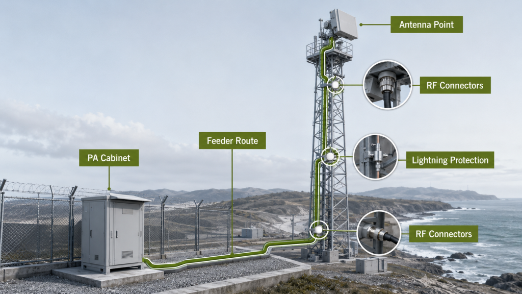
Feeder and connector loss must become a selection input when RF Power Amplifier Power Margin depends on a long, outdoor, multi-transition, high-frequency, or acceptance-critical RF path. Once the system architecture already defines a tower, mast, remote antenna, cabinet feedthrough, waterproof connector, or lightning protector, those parts are no longer installation details. They are conditions that decide the required PA output range.
This is where system integrators should pay attention: if the antenna path is known before procurement, the loss should be reviewed before the PA module is approved. Waiting until field installation turns a selection problem into a rework problem.
Which Field Conditions Trigger Loss-Based Selection?
Loss-based selection becomes necessary when the RF path is long enough or complex enough to change delivered output. Border and coastline projects often meet this condition because antenna placement is shaped by terrain, tower height, coastline visibility, and outdoor protection requirements.
Treat loss as a selection input when you see:
- Separate PA cabinet and antenna locations
- Long feeder cable runs
- Multiple connector transitions
- Waterproof joints in the antenna path
- Lightning protection in the outdoor path
- Bulkhead connectors through cabinets
- Adapter transitions during integration
- High-band or wideband operation
- Antenna-end acceptance requirements
For deeper cable-path review, use a focused reference such as RF Power Amplifier feeder cable loss instead of repeating the full measurement method inside the selection file.
What Happens If Loss Is Added Too Late?
If loss is added too late, the selected module may have to operate closer to its real limit. The team may then compensate with higher PA power, thicker feeder cable, shorter routes, extra cabinets, or a changed antenna position.
Key Takeaway: Feeder and connector loss should enter selection as soon as the installed RF path becomes predictable.
| Field Condition | Why It Matters | Selection Impact |
|---|---|---|
| Long feeder cable | Higher path loss | More PA output may be needed |
| More connectors | More transitions | Less usable margin |
| Waterproof joint | Outdoor RF boundary | Add loss and uncertainty |
| Lightning protector | Required protection point | Include in RF path |
| High-frequency band | Loss often rises | Check weakest band |
This table helps procurement and RF teams decide when path loss must be treated as an input, not a correction.
4. How to Check RF Power Margin After Feeder Loss
Loss changes the meaning of power margin because RF Power Amplifier Power Margin must remain after the installed RF path, not only before it. If the project target is antenna-end usable output, then feeder loss, connector loss, transition loss, and safety reserve must be subtracted before the remaining margin is judged. A PA that looks oversized at the output port may be only adequate, or even insufficient, at the antenna input.
The better check is simple: work backward from the required antenna-end output. Do not start with a convenient PA wattage and assume the rest of the RF chain is neutral.
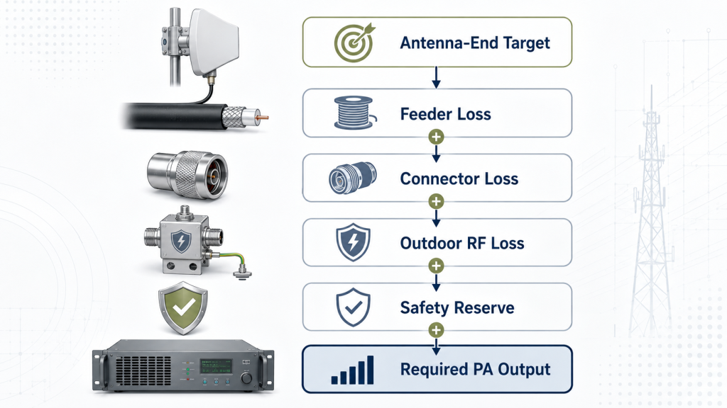
What Is the Better Calculation Logic?
The better logic is to define the antenna-end requirement first, then add the losses and reserve needed to reach it. This does not require turning the article into a dB-to-watt tutorial; it requires the right order of thinking.
A practical selection logic is:
- Required antenna-end usable output
- Plus feeder cable loss
- Plus connector and adapter loss
- Plus waterproof joint and lightning protector loss
- Plus frequency-related worst-case allowance
- Plus safety margin for field variation
- Equals required PA output capability
A general RF Power Amplifier power margin review should therefore be narrowed for border and coastline systems by subtracting the real feeder and connector path.
Why Is “More PA Power” Not Always the Best Fix?
More PA power may restore antenna-end output, but it can also raise heat, DC current, cabinet load, reflected-power stress, and protection events. Sometimes the better fix is shorter routing, better cable grade, fewer transitions, or a different cabinet position.
Key Takeaway: Real margin is the reserve left after the RF path has taken its share, not the reserve printed at the PA port.
| Starting Point | What It Protects | What It Can Miss |
|---|---|---|
| PA-port margin | Module-side reserve | Feeder and connector loss |
| Antenna-end target | Delivered output | Requires path data |
| Higher wattage PA | Output capacity | Thermal and DC pressure |
| Cleaner RF path | Delivered efficiency | Needs early layout work |
This table shows why power margin should be a system decision, not only a module decision.
5. What Border Sites Reveal About RF Power Margin
Border and coastline sites reveal that RF Power Amplifier Power Margin can be reduced by long outdoor feeder paths, exposed connector points, lightning protection, salt exposure, wind vibration, and difficult maintenance access. These projects rarely behave like short indoor test benches. The antenna is often placed where coverage geometry requires it, while the PA cabinet is placed where power, access, protection, and structure allow it.
Here’s the field reality: the PA may be healthy, but the RF chain may consume the reserve that the engineer expected to keep. That is why border and coastline C-UAS deployment should be reviewed from the antenna end backward.
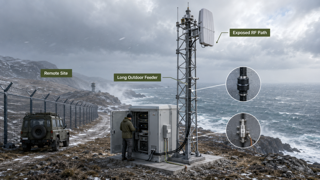
Which Site Patterns Create the Risk?
The risk usually appears when the antenna has to move away from the RF cabinet. A tower may give better line-of-sight, but it also adds feeder length and outdoor connection points.
Common patterns include:
- Border tower with cabinet at the base
- Coastline mast with exposed feeder routing
- Mountain or high-point antenna placement
- Remote station with limited maintenance access
- Multiple sites using the same PA rating but different cable paths
- Cabinet feedthroughs added for sealing and service access
Why Does Maintenance Access Matter?
Maintenance access matters because small RF path problems become expensive when the site is remote. If antenna-end output is too low after installation, changing feeder cable, replacing waterproof connectors, or moving a cabinet can delay acceptance.
Key Takeaway: Border and coastline projects make RF chain loss more visible because the path is longer, more exposed, and harder to rework.
| Deployment Pattern | Loss Risk | Better Planning Move |
|---|---|---|
| Tower antenna | Long vertical feeder | Estimate antenna-end margin early |
| Coastline mast | Salt and moisture exposure | Control outdoor connector list |
| Remote outpost | Hard maintenance | Use conservative path assumptions |
| Multiple sites | Uneven feeder length | Calculate worst-point margin |
| High-band antenna | Greater path sensitivity | Check weakest frequency |
This table helps you see why the same PA module can produce different usable margins at different border or coastline sites.
6. How to Count Connector Loss in RF Power Margin
Connectors, waterproof joints, and lightning protection add pressure because RF Power Amplifier Power Margin is affected by every transition between the PA output and antenna input. These parts are often necessary in outdoor systems, so the goal is not to avoid them all. The goal is to count them, control them, and include them in the loss budget before final selection.
The selection risk appears here: a single connector may look harmless, but a full outdoor path may contain enough transitions to change the real antenna-end reserve. This is especially true when temporary adapters appear during integration and are not recorded in the final path.
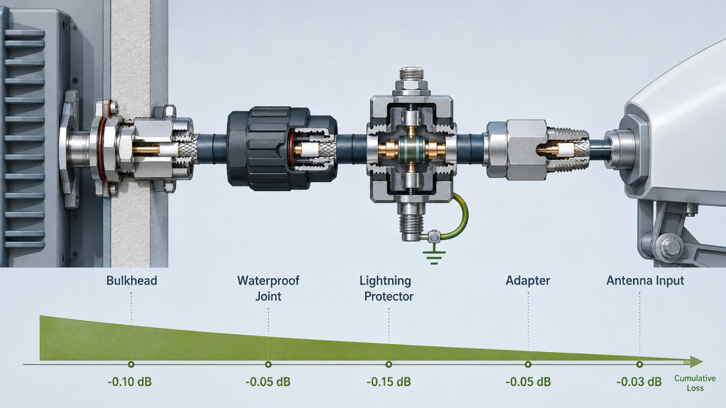
What Should Be Listed in the RF Path?
The RF path list should include every connection boundary that carries RF power. Mechanical-looking parts are still electrical parts when they sit between the PA and the antenna.
List these items before quoting margin:
- PA output connector
- Cabinet bulkhead connector
- Feeder cable connector pair
- Waterproof outdoor joint
- Lightning protector
- Adapter transition
- Combiner or splitter interface
- Antenna input connector
- Service test point
The selected RF cable grade for RF Power Amplifiers should match frequency, length, power level, duty cycle, outdoor routing, and required antenna-end reserve.
Why Do Temporary Adapters Create Confusion?
Temporary adapters create confusion because they may enter a test path but not the final drawing. If the acceptance result includes unplanned transitions, the measured output may look worse than expected.
Key Takeaway: Connector count is not a small detail in border C-UAS selection; it is part of the power-margin decision.
| RF Path Item | Possible Effect | Better Control |
|---|---|---|
| Bulkhead connector | Added boundary | Include in path list |
| Waterproof joint | Outdoor interface loss | Specify and inspect |
| Lightning protector | Required protection loss | Include in margin |
| Adapter transition | Unplanned loss | Remove or document |
| Combiner/splitter | Distribution loss | Calculate by channel |
This table keeps the team from treating necessary outdoor interfaces as invisible parts of the RF chain.
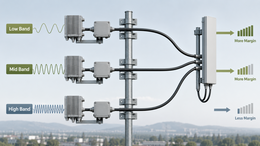
7. Why Do Frequency Band and Wideband Behavior Change Margin?
Frequency band and wideband behavior change margin because RF Power Amplifier Power Margin is not consumed evenly across every frequency. Feeder cable loss, connector behavior, adapter performance, and transition quality may look acceptable at one point but become more limiting at another. For wideband C-UAS systems, a center-frequency result can hide weakness at the band edge or high band.
Here’s the engineering point: power margin should be checked at the weakest required frequency, not only at the easiest frequency. A system that passes at a comfortable mid-band point may still have tight antenna-end reserve where feeder and connector loss are higher.
What Should Wideband Projects Check?
Wideband projects should check whether the installed RF chain supports enough delivered output across the required operating range. This does not mean repeating a full wideband verification article inside this topic; it means including loss margin across the band.
Check these items:
- Low, middle, and high frequency points
- Band-edge output after path loss
- Connector type across target frequency
- Cable grade at the highest required band
- Adapter and lightning protector frequency suitability
- Antenna-end target at the weakest band
For wideband systems, verified wideband RF Power Amplifier performance should be checked together with feeder and connector loss.
What Is the Procurement Mistake?
The procurement mistake is approving a PA rating based on one favorable band. If the system covers multiple RF channels, the weakest path and weakest frequency may define real margin.
Key Takeaway: Loss-inclusive margin must be reviewed across the required band, especially where high-frequency feeder loss or band-edge output is tighter.
| Frequency Review | What It Shows | Risk If Skipped |
|---|---|---|
| Center frequency | Comfortable baseline | False confidence |
| High band | Loss sensitivity | Low antenna-end reserve |
| Band edge | Weakest output point | Acceptance gap |
| Full required band | Usable margin range | Better selection evidence |
This table helps engineers avoid selecting PA output from the best-looking frequency point.
8. How to Prove RF Power Margin in Acceptance Reports
Reports should show loss-inclusive power margin by proving where RF Power Amplifier Power Margin was measured, what RF path was included, and whether protection status remained stable under the defined test condition. A report that only says “PA output passed” may be correct, but it does not prove that the installed antenna-end margin passed. The report must show whether feeder cable, connector count, waterproof joint, lightning protector, and measurement reference point were included.
This is where repeatability matters: a good acceptance record should let another engineer rebuild the test boundary and understand why the number was accepted. If the report cannot identify the reference point, the margin cannot be compared fairly later.
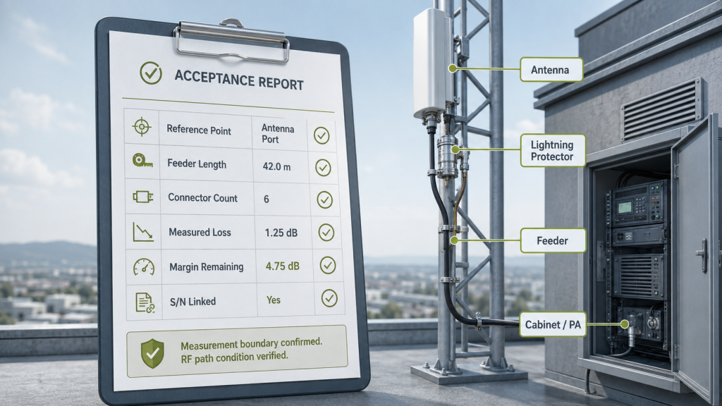
What Should the Acceptance Record Include?
The acceptance record should include enough information to separate module behavior from RF path behavior. It should not overload the customer with unnecessary paperwork, but it should document the conditions that change delivered output.
Record these items:
- Output reference point
- Feeder cable length and type
- Connector and adapter count
- Waterproof joint and lightning protector status
- Frequency points or band
- Forward power and reflected power
- VSWR or alarm status
- DC supply voltage under load
- Thermal condition and duty cycle
- Serial-number-linked evidence
Outdoor systems should also review RF Power Amplifier connector problems because connector quality affects insertion loss and reflected-power behavior.
How Can Source-Factory Evidence Help?
Source-factory evidence helps when it links the module S/N, test condition, RF path assumption, protection status, and repeatable output data. As a source factory for RF Power Amplifier modules and C-UAS core components, RF SKYPOWER can connect module-side test data with feeder path assumptions, connector loss, antenna-end targets, VSWR status, thermal margin, 28V DC supply behavior, and S/N-linked acceptance evidence. This helps system integrators compare factory data and field retest data without treating the PA module as the only possible cause.
Key Takeaway: A useful report proves the margin boundary, not only the wattage result.
| Weak Evidence | Better Evidence | Why It Matters |
|---|---|---|
| “Output passed” | Reference point recorded | Avoids boundary confusion |
| Generic PA report | S/N-linked test data | Supports retest |
| No feeder details | Cable path included | Shows delivered margin |
| No alarm record | Protection status shown | Confirms stable operation |
| One margin for all sites | Site-specific path notes | Avoids hidden weak points |
This table turns the acceptance file into a practical diagnostic tool instead of a simple pass/fail sheet.
9. What RFQ Data Defines Real RF Power Margin
Engineers should ask for antenna-end target power, feeder length, cable type, connector count, outdoor RF transitions, frequency band, duty cycle, supply margin, thermal condition, and acceptance reference point before quoting RF Power Amplifier Power Margin. If these details are missing, the supplier can only quote module-side wattage and cannot judge real delivered reserve. That creates risk for both the buyer and the factory.
The better check is simple: do not ask only “how many watts do we need?” Ask “where must those watts remain after the RF path?” That question changes the RFQ from a catalog request into an engineering selection.
Which RFQ Items Matter Most?
The most useful RFQ items are the ones that define the installed path and the acceptance boundary. They let the supplier judge whether the requested PA rating is realistic or whether the layout should be changed before purchase.
Ask for:
- PA-port target or antenna-end target
- Required antenna-end usable output
- Frequency range and weakest band
- PA cabinet location
- Antenna location
- Feeder length and cable model
- Connector quantity and connector type
- Waterproof joints and lightning protection
- Adapter transitions and bulkhead points
- Combiner or splitter structure
- Outdoor exposure conditions
- Duty cycle and operating temperature
- 28V DC supply margin
- Acceptance measurement point
- Need for One Report One Unit evidence
In border tower or coastline deployments, antenna distance affects RF Power Amplifier selection because a remote antenna can consume margin before the signal reaches the radiator.
What If the Path Is Not Final Yet?
If the path is not final, give a preliminary range rather than nothing. Even an estimated feeder length, expected connector list, and target antenna point can reveal whether the PA choice is safe or too tight.
Key Takeaway: A good RFQ defines the output target, the installed RF path, and the acceptance boundary before wattage is approved.
| RFQ Item | Why It Matters | Better Question |
|---|---|---|
| Target output point | Defines margin boundary | PA port or antenna end? |
| Feeder length | Drives path loss | What is the longest site path? |
| Connector count | Adds cumulative transitions | What is in the final RF path? |
| Frequency band | Changes loss severity | Which band is weakest? |
| Duty cycle | Affects heat and DC load | Is full-load operation expected? |
This table helps procurement teams ask questions that prevent late redesign.
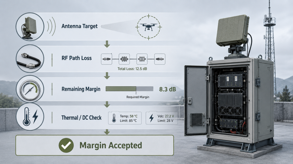
10. How Do You Decide If Margin Is Enough After Loss?
You decide margin is enough after loss only when RF Power Amplifier Power Margin remains stable after feeder loss, connector loss, outdoor RF transitions, frequency behavior, thermal load, DC supply limits, protection status, and long-term field conditions are included. A PA is not selected correctly just because its module label is higher than the target wattage. It is selected correctly when the antenna-end target still has reserve under the installed path.
Here’s the final decision path: start at the antenna end, move backward through the RF chain, then confirm that the PA, cable, connectors, cabinet, supply, and protection logic can support the result. If the margin is too tight, do not automatically choose a larger PA before checking the path.
What Decision Sequence Works Best?
A practical decision sequence keeps the team from skipping the RF chain. It also prevents using higher wattage to compensate for avoidable layout loss.
Use this order:
- Confirm the required output point
- Define the target frequency range
- Identify the weakest required band
- Map feeder cable length and type
- Count connector, waterproof, lightning, adapter, and bulkhead transitions
- Estimate antenna-end output after loss
- Check remaining safety margin
- Review thermal and 28V DC supply capacity
- Check VSWR, reflected power, temperature, and alarm behavior
- Confirm repeatable acceptance evidence
The final RF Power Amplifier cable bending loss should also be considered when outdoor installations force feeder cables through tight routing paths.
What Is the Best Corrective Action?
The best corrective action depends on the cause of the tight margin. Sometimes the right answer is a higher PA rating. In other cases, it is better cable grade, fewer connectors, shorter routing, closer cabinet placement, cleaner adapter control, or a different antenna location.
Key Takeaway: Enough margin means enough antenna-end reserve after the installed RF chain and operating conditions are included.
| If the Problem Is… | Start With… | Avoid First |
|---|---|---|
| Long feeder loss | Shorter route or better cable | Blind PA oversizing |
| Many transitions | Connector path simplification | Ignoring cumulative loss |
| High-band weakness | Band-specific margin check | Center-frequency approval |
| Thermal pressure | Cabinet and duty review | Higher output without cooling |
| Field acceptance dispute | Reference point record | Comparing unlike test points |
This table gives engineers a practical path from problem diagnosis to selection action.
FAQ
Can I use PA-port power margin for a border C-UAS RFQ?
Yes, but only as an early module-side reference. For a border or coastline RFQ, you should also define feeder length, connector count, outdoor transitions, frequency band, and antenna-end target so the supplier can judge real margin.
What is the best way to define RF power margin after feeder loss?
The best way is to start from the required antenna-end output and work backward through feeder cable loss, connector loss, waterproof joints, lightning protection, adapter transitions, and safety reserve. This prevents module wattage from being treated as delivered antenna power.
How do I know if connector loss is affecting antenna-end margin?
You know connector loss may be affecting margin when antenna-end power is lower than PA-port power, readings change after retightening connectors, reflected power rises, or different sites with the same PA rating show different delivered output. Count and document every RF transition before judging the module.
What should I check before choosing 100W or 200W for coastline C-UAS?
Check antenna-end target power, feeder length, cable grade, connector count, waterproof joints, lightning protection, weakest frequency band, duty cycle, 28V supply capacity, thermal margin, and acceptance reference point. The right choice depends on delivered margin, not only PA label wattage.
When should I ask for loss-inclusive acceptance evidence?
Ask for loss-inclusive acceptance evidence when the system uses a long feeder path, outdoor antenna, multiple RF transitions, wideband operation, remote site maintenance, or antenna-end output acceptance. The report should show reference point, path condition, frequency, protection status, and S/N-linked data.
Conclusion
RF Power Amplifier power margin is only useful when it remains after the installed RF chain. In border and coastline C-UAS systems, feeder cable length, connector count, waterproof joints, lightning protection, adapter transitions, cable routing, frequency band, and outdoor exposure can all reduce antenna-end usable output. A margin that looks sufficient at the PA port may become too small after the signal passes through the real field path.
For engineers, the practical decision is clear: define the required antenna-end output first, then work backward through feeder loss, connector loss, outdoor RF transitions, thermal margin, supply margin, and protection behavior. Do not approve PA output power only from the module label, a short bench path, or a report that does not state the measurement reference point.
As an RF Power Amplifier module and C-UAS core component source factory, RF SKYPOWER supports border and coastline C-UAS projects by reviewing PA output, feeder path, connector loss, outdoor RF transitions, antenna-end target, supply margin, thermal margin, protection feedback, and repeatable acceptance evidence before final integration. If your project needs to confirm feeder loss, connector loss, antenna-end target, and PA output margin before final selection, you can contact us today to review the RF chain before the layout becomes expensive to change.
Field-ready C-UAS performance starts with loss-inclusive RF decisions, not catalog margin at the PA port.